User Manual
Page 32
Chapter summary 2 2.1 Before you proceed 2-1 2.2 Motherboard overview 2-2 2.3 Building your computer system 2-36 2.4 Starting up for the first time 2-53 2.5 Turning off the computer 2-54 ASUS MAXIMUS IV GENE-Z/GEN3
Chapter summary 2 2.1 Before you proceed 2-1 2.2 Motherboard overview 2-2 2.3 Building your computer system 2-36 2.4 Starting up for the first time 2-53 2.5 Turning off the computer 2-54 ASUS MAXIMUS IV GENE-Z/GEN3
User Manual
Page 33
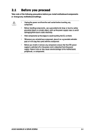
... as the power supply case, to avoid damaging them due to static electricity. • Hold components by the edges to the motherboard, peripherals, or components. ASUS MAXIMUS IV GENE-Z/GEN3 2-1 Failure to do so may cause severe damage to avoid touching the ICs on them. • Whenever you uninstall any component, place it on a grounded...
... as the power supply case, to avoid damaging them due to static electricity. • Hold components by the edges to the motherboard, peripherals, or components. ASUS MAXIMUS IV GENE-Z/GEN3 2-1 Failure to do so may cause severe damage to avoid touching the ICs on them. • Whenever you uninstall any component, place it on a grounded...
User Manual
Page 35
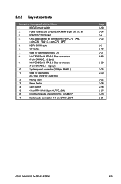
... 2.0 connectors (10-1 pin USB910; Digital audio connector (4-1 pin SPDIF_OUT) Page 2-19 2-34 2-4 2-32 2-5 2-19 2-31 2-28 2-29 2-35 2-30 2-22 2-18 2-18 2-27 2-33 2-31 ASUS MAXIMUS IV GENE-Z/GEN3 2-3 ROG Connect switch 2. Start Switch 15. Reset Switch 14. Clear RTC RAM (3-pin CLRTC_SW) 16. Power connectors (24-pin EATXPWR, 8-pin EATX12V) 3.
... 2.0 connectors (10-1 pin USB910; Digital audio connector (4-1 pin SPDIF_OUT) Page 2-19 2-34 2-4 2-32 2-5 2-19 2-31 2-28 2-29 2-35 2-30 2-22 2-18 2-18 2-27 2-33 2-31 ASUS MAXIMUS IV GENE-Z/GEN3 2-3 ROG Connect switch 2. Start Switch 15. Reset Switch 14. Clear RTC RAM (3-pin CLRTC_SW) 16. Power connectors (24-pin EATXPWR, 8-pin EATX12V) 3.
User Manual
Page 37
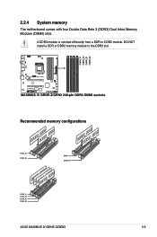
2.2.4 System memory The motherboard comes with four Double Data Rate 3 (DDR3) Dual Inline Memory Modules (DIMM) slots. DO NOT install a DDR or DDR2 memory module to the DDR3 slot. Recommended memory configurations ASUS MAXIMUS IV GENE-Z/GEN3 2-5 A DDR3 module is notched differently from a DDR or DDR2 module.
2.2.4 System memory The motherboard comes with four Double Data Rate 3 (DDR3) Dual Inline Memory Modules (DIMM) slots. DO NOT install a DDR or DDR2 memory module to the DDR3 slot. Recommended memory configurations ASUS MAXIMUS IV GENE-Z/GEN3 2-5 A DDR3 module is notched differently from a DDR or DDR2 module.
User Manual
Page 39
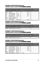
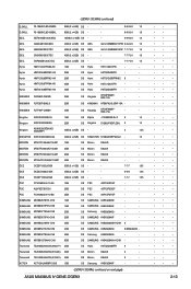
...65 • • • 1.65 • • 1.66 • • • MAXIMUS IV GENE-Z/GEN3 Motherboard Qualified Vendors Lists (QVL) DDR�3�-2��3��3���3��M�H�&#... DS - - - 1.5~1.7 • • DS Kingmax - - - • • ASUS MAXIMUS IV GENE-Z/GEN3 2-7 Transcend TX2400KLU-4GK(374243)(XMP) 2GB DS - - MAXIMUS IV GENE-Z/GEN3 Motherboard Qualified Vendors Lists (QVL) DDR�3�-2�4��0�0��M��H�...
...65 • • • 1.65 • • 1.66 • • • MAXIMUS IV GENE-Z/GEN3 Motherboard Qualified Vendors Lists (QVL) DDR�3�-2��3��3���3��M�H�&#... DS - - - 1.5~1.7 • • DS Kingmax - - - • • ASUS MAXIMUS IV GENE-Z/GEN3 2-7 Transcend TX2400KLU-4GK(374243)(XMP) 2GB DS - - MAXIMUS IV GENE-Z/GEN3 Motherboard Qualified Vendors Lists (QVL) DDR�3�-2�4��0�0��M��H�...
User Manual
Page 41
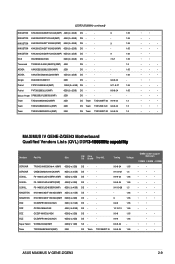
...8226; • • • • • • • • • • MAXIMUS IV GENE-Z/GEN3 Motherboard Qualified Vendors Lists (QVL) DDR�3��-�1��8��6�6��M��H�&#...• • • • • • • • • • • • • • • ASUS MAXIMUS IV GENE-Z/GEN3 2-9 (DDR3-2000MHz continued) KINGSTON KHX2000C9AD3W1K2/4GX(XMP) 4GB (2 x 2GB) DS - - 9 1.65 KINGSTON KHX2000C9D3T1K2/4GX(XMP) 4GB (2 x 2GB) DS ...
...8226; • • • • • • • • • • MAXIMUS IV GENE-Z/GEN3 Motherboard Qualified Vendors Lists (QVL) DDR�3��-�1��8��6�6��M��H�&#...• • • • • • • • • • • • • • • ASUS MAXIMUS IV GENE-Z/GEN3 2-9 (DDR3-2000MHz continued) KINGSTON KHX2000C9AD3W1K2/4GX(XMP) 4GB (2 x 2GB) DS - - 9 1.65 KINGSTON KHX2000C9D3T1K2/4GX(XMP) 4GB (2 x 2GB) DS ...
User Manual
Page 43
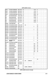
...; • • • • • • • • • • • • • • • • • • • • • • • • • ASUS MAXIMUS IV GENE-Z/GEN3 2-11 Super Talent WB160UX6G8(XMP) 6GB (3 x 2GB) DS - - - - KINGSTON KHX1600C9D3K3/12GX(XMP) 12GB (3 x 4GB) DS N/A - - 1.65 KINGSTON KHX1600C9D3K6/24GX(XMP) 24GB (6 x 4GB) DS - - 9 1.65 KINGSTON...
...; • • • • • • • • • • • • • • • • • • • • • • • • • ASUS MAXIMUS IV GENE-Z/GEN3 2-11 Super Talent WB160UX6G8(XMP) 6GB (3 x 2GB) DS - - - - KINGSTON KHX1600C9D3K3/12GX(XMP) 12GB (3 x 4GB) DS N/A - - 1.65 KINGSTON KHX1600C9D3K6/24GX(XMP) 24GB (6 x 4GB) DS - - 9 1.65 KINGSTON...
User Manual
Page 45
... OCZ3P1333LV4GK 4GB (2 x 2GB) DS - - 7-7-7 1.65 PSC PC310600U-9-10-A0 1GB SS PSC A3P1GF3FGF - - ACTICA ACT1GHU64B8F1333S 1GB SS Samsung K4B1G0846F - - (DDR3-1333MHz continued on next page) ASUS MAXIMUS IV GENE-Z/GEN3 • • • • • • • • • • • • • • • • • • • • • • • • •...
... OCZ3P1333LV4GK 4GB (2 x 2GB) DS - - 7-7-7 1.65 PSC PC310600U-9-10-A0 1GB SS PSC A3P1GF3FGF - - ACTICA ACT1GHU64B8F1333S 1GB SS Samsung K4B1G0846F - - (DDR3-1333MHz continued on next page) ASUS MAXIMUS IV GENE-Z/GEN3 • • • • • • • • • • • • • • • • • • • • • • • • •...
User Manual
Page 47
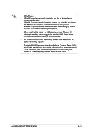
Hence, a total installed memory of less than 3GB is recommended. • It is recommended to install the memory modules from a memory module. ASUS MAXIMUS IV GENE-Z/GEN3 2-15 • 4 DIMM slots: 1 DIMM: Supports one module inserted in any slot as single-channel memory configuration. 2 DIMMs: Support one pair of modules inserted into ...
Hence, a total installed memory of less than 3GB is recommended. • It is recommended to install the memory modules from a memory module. ASUS MAXIMUS IV GENE-Z/GEN3 2-15 • 4 DIMM slots: 1 DIMM: Supports one module inserted in any slot as single-channel memory configuration. 2 DIMMs: Support one pair of modules inserted into ...
User Manual
Page 49
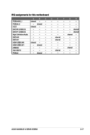
EHCI#0 (USB2.0) - - - PCIEx4 - shared - - - - - - - - - - - - - - - - JMB362 - - - shared - - - - ASUS MAXIMUS IV GENE-Z/GEN3 2-17 shared - EHCI#1 (USB2.0) - - - High Definition Audio - - - PCIEx8_2 - I.G.D shared - - SATA #0 - - - shared - shared - - shared - - - - - - - - IRQ assignments for this motherboard A B C PCIEx16/8_1 shared - - shared - shared - - D E F G H - - - - - - - - - - - - - - - - - - - SATA #1 - - - ASM ...
EHCI#0 (USB2.0) - - - PCIEx4 - shared - - - - - - - - - - - - - - - - JMB362 - - - shared - - - - ASUS MAXIMUS IV GENE-Z/GEN3 2-17 shared - EHCI#1 (USB2.0) - - - High Definition Audio - - - PCIEx8_2 - I.G.D shared - - SATA #0 - - - shared - shared - - shared - - - - - - - - IRQ assignments for this motherboard A B C PCIEx16/8_1 shared - - shared - shared - - D E F G H - - - - - - - - - - - - - - - - - - - SATA #1 - - - ASM ...
User Manual
Page 51
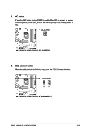
ASUS MAXIMUS IV GENE-Z/GEN3 2-19 ROG Connect switch Move the slide switch to ON before POST to quickly load the preset profile (GO_Button file) for temporary overclocking when in OS. 4. GO button Press the GO button before you use the ROG Connect function. or press it to enable MemOK! 3.
ASUS MAXIMUS IV GENE-Z/GEN3 2-19 ROG Connect switch Move the slide switch to ON before POST to quickly load the preset profile (GO_Button file) for temporary overclocking when in OS. 4. GO button Press the GO button before you use the ROG Connect function. or press it to enable MemOK! 3.
User Manual
Page 53
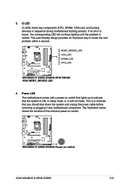
... an error is found , the corresponding LED will continue lighting until the problem is ON, in sleep mode, or in sequence during motherboard booting process. ASUS MAXIMUS IV GENE-Z/GEN3 2-21
... an error is found , the corresponding LED will continue lighting until the problem is ON, in sleep mode, or in sequence during motherboard booting process. ASUS MAXIMUS IV GENE-Z/GEN3 2-21
User Manual
Page 55
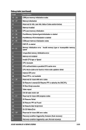
... CPU micro-code is not found or micro-code update is failed 5A Internal CPU error 5B Reset PPI is called by user (Forced recovery) ASUS MAXIMUS IV GENE-Z/GEN3 2-23
... CPU micro-code is not found or micro-code update is failed 5A Internal CPU error 5B Reset PPI is called by user (Forced recovery) ASUS MAXIMUS IV GENE-Z/GEN3 2-23
User Manual
Page 57
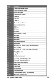
... Initialization System Reset USB hot plug PCI bus hot plug Clean-up of NVRAM Configuration Reset (reset of NVRAM settings) Reserved for future AMI codes ASUS MAXIMUS IV GENE-Z/GEN3 2-25
... Initialization System Reset USB hot plug PCI bus hot plug Clean-up of NVRAM Configuration Reset (reset of NVRAM settings) Reserved for future AMI codes ASUS MAXIMUS IV GENE-Z/GEN3 2-25
User Manual
Page 59
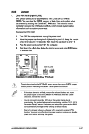
... battery and move the cap back to clear the Real Time Clock (RTC) RAM in CMOS, which include system setup information such as system passwords. ASUS MAXIMUS IV GENE-Z/GEN3 2-27 Clear RTC RAM (3-pin CLRTC) This jumper allows you to pins 1-2. 3. Turn OFF the computer and unplug the power cord. 2. Hold down and reboot...
... battery and move the cap back to clear the Real Time Clock (RTC) RAM in CMOS, which include system setup information such as system passwords. ASUS MAXIMUS IV GENE-Z/GEN3 2-27 Clear RTC RAM (3-pin CLRTC) This jumper allows you to pins 1-2. 3. Turn OFF the computer and unplug the power cord. 2. Hold down and reboot...
User Manual
Page 61
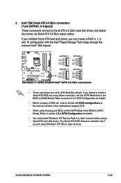
...; Z68 chipset. • These connectors are using these connectors, set , refer to create a Serial ATA RAID set using Windows® XP SP2 or later versions. ASUS MAXIMUS IV GENE-Z/GEN3 2-29 Refer to section 3.5.4 SATA Configuration for details. • You must install Windows® XP Service Pack 3 or later versions before using hot-plug and...
...; Z68 chipset. • These connectors are using these connectors, set , refer to create a Serial ATA RAID set using Windows® XP SP2 or later versions. ASUS MAXIMUS IV GENE-Z/GEN3 2-29 Refer to section 3.5.4 SATA Configuration for details. • You must install Windows® XP Service Pack 3 or later versions before using hot-plug and...
User Manual
Page 63
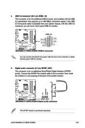
... panel USB 3.0 box to this connector, then install the module to a slot opening at the back of the system chassis. ASUS MAXIMUS IV GENE-Z/GEN3 2-31 Digital audio connector (4-1 pin SPDIF_OUT) This connector is available from your system chassis, with the USB 3.0 specificaton that supports up to obtain the front ...
... panel USB 3.0 box to this connector, then install the module to a slot opening at the back of the system chassis. ASUS MAXIMUS IV GENE-Z/GEN3 2-31 Digital audio connector (4-1 pin SPDIF_OUT) This connector is available from your system chassis, with the USB 3.0 specificaton that supports up to obtain the front ...
User Manual
Page 65
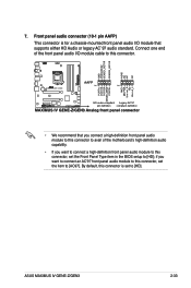
Front panel audio connector (10-1 pin AAFP) This connector is set the Front Panel Type item in the BIOS setup to [AC97]. ASUS MAXIMUS IV GENE-Z/GEN3 2-33 Connect one end of the front panel audio I /O module that you connect a high-definition front panel audio module to this connector to avail of ...
Front panel audio connector (10-1 pin AAFP) This connector is set the Front Panel Type item in the BIOS setup to [AC97]. ASUS MAXIMUS IV GENE-Z/GEN3 2-33 Connect one end of the front panel audio I /O module that you connect a high-definition front panel audio module to this connector to avail of ...
User Manual
Page 67
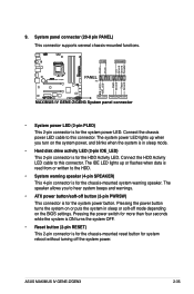
... several chassis-mounted functions. • System power LED (2-pin PLED) This 2-pin connector is for the chassis-mounted reset button for the HDD Activity LED. ASUS MAXIMUS IV GENE-Z/GEN3 2-35 9.
... several chassis-mounted functions. • System power LED (2-pin PLED) This 2-pin connector is for the chassis-mounted reset button for the HDD Activity LED. ASUS MAXIMUS IV GENE-Z/GEN3 2-35 9.
User Manual
Page 69
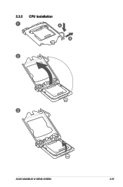
2.3.2 CPU installation 1 A B 2 3 ASUS MAXIMUS IV GENE-Z/GEN3 2-37
2.3.2 CPU installation 1 A B 2 3 ASUS MAXIMUS IV GENE-Z/GEN3 2-37


