User Manual
Page 6
... a RAID driver disk 4-32 4.5.1 Creating a RAID driver disk without entering the OS.... 4-32 4.5.2 Creating a RAID driver disk in Windows 4-32 4.5.3 Installing the RAID driver during Windows® OS installation 4-33 4.5.4 Using a USB floppy disk drive 4-34 Chapter 5: Multiple GPU technology support 5.1 ATI® CrossFireX™ technology 5-1 5.1.1 Requirements 5-1 5.1.2 Before you begin 5-1 5.1.3 Installing CrossFireX graphics cards 5-2 5.1.4 Installing the device drivers 5-3 5.1.5 Enabling the ATI® CrossFireX™ technology 5-3 5.2 NVIDIA® SLI™ technology...
... a RAID driver disk 4-32 4.5.1 Creating a RAID driver disk without entering the OS.... 4-32 4.5.2 Creating a RAID driver disk in Windows 4-32 4.5.3 Installing the RAID driver during Windows® OS installation 4-33 4.5.4 Using a USB floppy disk drive 4-34 Chapter 5: Multiple GPU technology support 5.1 ATI® CrossFireX™ technology 5-1 5.1.1 Requirements 5-1 5.1.2 Before you begin 5-1 5.1.3 Installing CrossFireX graphics cards 5-2 5.1.4 Installing the device drivers 5-3 5.1.5 Enabling the ATI® CrossFireX™ technology 5-3 5.2 NVIDIA® SLI™ technology...

User Manual
Page 17
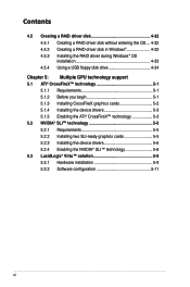
... IV GENE-Z/GEN3 specifications summary Back Panel I/O Ports Internal Connectors Manageability BIOS Features Software Form Factor 1 x PS/2 Keyboard/Mouse port 2 x External SATA ports 1 x LAN (RJ45) port 2 x USB 3.0/2.0 ports 8 x USB 2.0/1.1 ports (one is also for ROG Connect) 1 x S/PDIF Out (Optical) 1 x HDMI port 1 x Clr CMOS switch 8-channel Audio I/O 1 x USB 3.0 connector (Red) supports additional 2 USB 3.0 ports 2 x USB 2.0 connectors support additional 4 USB 2.0 ports 6 x SATA connectors: 2 x SATA 6Gb/s connectors (Red) & 4 x SATA 3Gb/s connectors (Gray) 5 x Fan connectors: 2 x CPU...
... IV GENE-Z/GEN3 specifications summary Back Panel I/O Ports Internal Connectors Manageability BIOS Features Software Form Factor 1 x PS/2 Keyboard/Mouse port 2 x External SATA ports 1 x LAN (RJ45) port 2 x USB 3.0/2.0 ports 8 x USB 2.0/1.1 ports (one is also for ROG Connect) 1 x S/PDIF Out (Optical) 1 x HDMI port 1 x Clr CMOS switch 8-channel Audio I/O 1 x USB 3.0 connector (Red) supports additional 2 USB 3.0 ports 2 x USB 2.0 connectors support additional 4 USB 2.0 ports 6 x SATA connectors: 2 x SATA 6Gb/s connectors (Red) & 4 x SATA 3Gb/s connectors (Gray) 5 x Fan connectors: 2 x CPU...
User Manual
Page 24
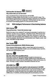
... ROG MAXIMUS IV GENE-Z/GEN3, you'll be assured of a button. Tweak it always takes time for the system to handle the demands of your enter the OS! Monitor the status of an overclocking experience. BIOS Print One click, easily share your graphics cards and memory DIMMs status in real-time via a notebook-just like a race car engineer-with ROG Connect. Diagram, power, reset button, flash BIOS through a USB cable, allowing...
... ROG MAXIMUS IV GENE-Z/GEN3, you'll be assured of a button. Tweak it always takes time for the system to handle the demands of your enter the OS! Monitor the status of an overclocking experience. BIOS Print One click, easily share your graphics cards and memory DIMMs status in real-time via a notebook-just like a race car engineer-with ROG Connect. Diagram, power, reset button, flash BIOS through a USB cable, allowing...
User Manual
Page 33
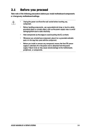
... the power supply case, to avoid damaging them due to static electricity. • Hold components by the edges to the motherboard, peripherals, or components. ASUS MAXIMUS IV GENE-Z/GEN3 2-1 2.1 Before you proceed Take note of the following precautions before you install motherboard components or change any motherboard settings. • Unplug the power cord from the wall socket before touching any component, ensure that the ATX power supply is switched off...
... the power supply case, to avoid damaging them due to static electricity. • Hold components by the edges to the motherboard, peripherals, or components. ASUS MAXIMUS IV GENE-Z/GEN3 2-1 2.1 Before you proceed Take note of the following precautions before you install motherboard components or change any motherboard settings. • Unplug the power cord from the wall socket before touching any component, ensure that the ATX power supply is switched off...
User Manual
Page 39
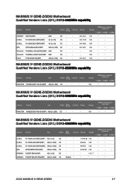
...;��a��b���i�l�i�ty� Vendors Part No. Size SS/DS Chip Brand Chip No. Timing CORSAIR CMGTX3(XMP) 2GB DS - - Size SS/DS Chip Brand Chip No. Voltage DIMM socket support (Optional) 1 DIMM 2 DIMM 4 DIMM 1.65 • • MAXIMUS IV GENE-Z/GEN3 Motherboard Qualified Vendors Lists (QVL) DDR�3�-2�2��5�0��M��H�...
...;��a��b���i�l�i�ty� Vendors Part No. Size SS/DS Chip Brand Chip No. Timing CORSAIR CMGTX3(XMP) 2GB DS - - Size SS/DS Chip Brand Chip No. Voltage DIMM socket support (Optional) 1 DIMM 2 DIMM 4 DIMM 1.65 • • MAXIMUS IV GENE-Z/GEN3 Motherboard Qualified Vendors Lists (QVL) DDR�3�-2�2��5�0��M��H�...
User Manual
Page 41
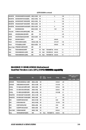
...; • • MAXIMUS IV GENE-Z/GEN3 Motherboard Qualified Vendors Lists (QVL) DDR�3��-�1��8��6�6��M��H���z��c���a��p���a��b���i�l�i�ty� Vendors Part No. Size SS/ DS Chip Brand Chip NO. Patriot PX7312G2000ELK...
...; • • MAXIMUS IV GENE-Z/GEN3 Motherboard Qualified Vendors Lists (QVL) DDR�3��-�1��8��6�6��M��H���z��c���a��p���a��b���i�l�i�ty� Vendors Part No. Size SS/ DS Chip Brand Chip NO. Patriot PX7312G2000ELK...
User Manual
Page 57
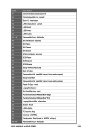
... SCSI Enable Setup Verifying Password Start of Setup Reserved for ASL (see ASL Status Codes section below)* Setup Input Wait Reserved for ASL (see ASL Status Codes section below) Ready To Boot event Legacy Boot event Exit Boot Services event Runtime Set Virtual Address MAP Begin Runtime Set Virtual Address MAP End Legacy Option ROM Initialization System Reset USB hot plug PCI bus hot plug Clean-up of NVRAM Configuration Reset (reset of NVRAM settings) Reserved for future AMI codes ASUS MAXIMUS IV GENE-Z/GEN3 2-25 Code...
... SCSI Enable Setup Verifying Password Start of Setup Reserved for ASL (see ASL Status Codes section below)* Setup Input Wait Reserved for ASL (see ASL Status Codes section below) Ready To Boot event Legacy Boot event Exit Boot Services event Runtime Set Virtual Address MAP Begin Runtime Set Virtual Address MAP End Legacy Option ROM Initialization System Reset USB hot plug PCI bus hot plug Clean-up of NVRAM Configuration Reset (reset of NVRAM settings) Reserved for future AMI codes ASUS MAXIMUS IV GENE-Z/GEN3 2-25 Code...
User Manual
Page 59
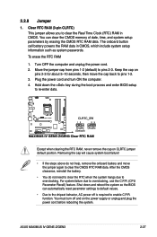
... on the power supply or unplug and plug the power cord before rebooting the system. For system failure due to pins 1-2. 3. You can automatically reset parameter settings to default values. • Due to overclocking. Plug the power cord and turn off is required to clear the Real Time Clock (RTC) RAM in CMOS, which include system setup information such as system passwords. You must turn ON the computer. 4. ASUS MAXIMUS IV GENE-Z/GEN3 2-27 2.2.8 Jumper 1. Keep...
... on the power supply or unplug and plug the power cord before rebooting the system. For system failure due to pins 1-2. 3. You can automatically reset parameter settings to default values. • Due to overclocking. Plug the power cord and turn off is required to clear the Real Time Clock (RTC) RAM in CMOS, which include system setup information such as system passwords. You must turn ON the computer. 4. ASUS MAXIMUS IV GENE-Z/GEN3 2-27 2.2.8 Jumper 1. Keep...
User Manual
Page 61
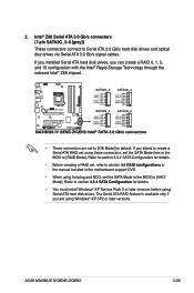
... creating a RAID set, refer to section 4.4 RAID configurations or the manual bundled in the BIOS to [RAID Mode]. If you installed Serial ATA hard disk drives, you can create a RAID 0, 1, 5, and 10 configuration with the Intel® Rapid Storage Technology through the onboard Intel® Z68 chipset. • These connectors are using these connectors, set the SATA Mode in the motherboard support DVD. • When using Serial ATA hard disk drives. If you are set using Windows® XP SP2 or later versions. ASUS MAXIMUS IV GENE-Z/GEN3 2-29 The Serial ATA RAID feature...
... creating a RAID set, refer to section 4.4 RAID configurations or the manual bundled in the BIOS to [RAID Mode]. If you installed Serial ATA hard disk drives, you can create a RAID 0, 1, 5, and 10 configuration with the Intel® Rapid Storage Technology through the onboard Intel® Z68 chipset. • These connectors are using these connectors, set the SATA Mode in the motherboard support DVD. • When using Serial ATA hard disk drives. If you are set using Windows® XP SP2 or later versions. ASUS MAXIMUS IV GENE-Z/GEN3 2-29 The Serial ATA RAID feature...
User Manual
Page 67
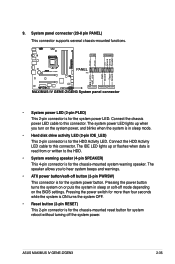
Connect the HDD Activity LED cable to this connector. Pressing the power switch for more than four seconds while the system is ON turns the system OFF. • Reset button (2-pin RESET) This 2-pin connector is for the chassis-mounted reset button for the system power LED. ASUS MAXIMUS IV GENE-Z/GEN3 2-35 Pressing the power button turns the system on the BIOS settings. System panel connector (20-8 pin PANEL) This connector supports several chassis-mounted functions. • System power LED (2-pin PLED) This 2-pin connector is for the HDD Activity LED. The IDE LED lights ...
Connect the HDD Activity LED cable to this connector. Pressing the power switch for more than four seconds while the system is ON turns the system OFF. • Reset button (2-pin RESET) This 2-pin connector is for the chassis-mounted reset button for the system power LED. ASUS MAXIMUS IV GENE-Z/GEN3 2-35 Pressing the power button turns the system on the BIOS settings. System panel connector (20-8 pin PANEL) This connector supports several chassis-mounted functions. • System power LED (2-pin PLED) This 2-pin connector is for the HDD Activity LED. The IDE LED lights ...

User Manual
Page 89
.... • If the system fails to boot after POST, press + + , or press the reset button on your motherboard if you want to use as storage device configuration, overclocking settings, advanced power management, and boot device configuration that are for information on how to ensure system compatibility and stability. When you start up the computer, the system provides you change modes from the Exit menu or from the available options using a keyboard or a USB mouse.
.... • If the system fails to boot after POST, press + + , or press the reset button on your motherboard if you want to use as storage device configuration, overclocking settings, advanced power management, and boot device configuration that are for information on how to ensure system compatibility and stability. When you start up the computer, the system provides you change modes from the Exit menu or from the available options using a keyboard or a USB mouse.
User Manual
Page 109
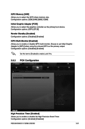
... Memory [64M] Allows you to enable or disable iGPU multi-monitor. Configuration options: [Disabled] [Enabled] Set this item to [Enabled] to enable Lucid Virtu. 3.5.3 PCH Configuration High Precision Timer [Enabled] Allows you to select the graphics controller as the primary output. Ensure to set Initial Graphic Adapter to enable or disable the High Precision Event Timer. Configuration options: [Enabled] [Disabled] ROG MAXIMUS IV GENE-Z/GEN3 3-21 Configuration options: [32M] [64M] [96M] [128M] Initial Graphic Adapter [PCIE] Allows you to [iGPU] when using the onboard GPU...
... Memory [64M] Allows you to enable or disable iGPU multi-monitor. Configuration options: [Disabled] [Enabled] Set this item to [Enabled] to enable Lucid Virtu. 3.5.3 PCH Configuration High Precision Timer [Enabled] Allows you to select the graphics controller as the primary output. Ensure to set Initial Graphic Adapter to enable or disable the High Precision Event Timer. Configuration options: [Enabled] [Disabled] ROG MAXIMUS IV GENE-Z/GEN3 3-21 Configuration options: [32M] [64M] [96M] [128M] Initial Graphic Adapter [PCIE] Allows you to [iGPU] when using the onboard GPU...

User Manual
Page 129
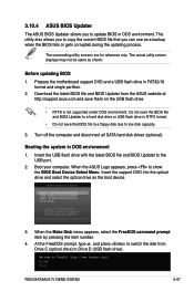
... MAXIMUS IV GENE-Z/GEN3 3-41 If there is potentially risky. ASUS Update: Updates the BIOS in the future. Inappropriate BIOS updating may result in case you to update your BIOS if necessary. ASUS CrashFree BIOS 3: Restores the BIOS using the motherboard support DVD and a USB flash disk drive. Refer to the corresponding sections for this chapter to manage and update the motherboard BIOS setup program. 1. Carefully follow the instructions of the original motherboard BIOS file to a USB flash disk in the system's failure to download the latest BIOS file...
... MAXIMUS IV GENE-Z/GEN3 3-41 If there is potentially risky. ASUS Update: Updates the BIOS in the future. Inappropriate BIOS updating may result in case you to update your BIOS if necessary. ASUS CrashFree BIOS 3: Restores the BIOS using the motherboard support DVD and a USB flash disk drive. Refer to the corresponding sections for this chapter to manage and update the motherboard BIOS setup program. 1. Carefully follow the instructions of the original motherboard BIOS file to a USB flash disk in the system's failure to download the latest BIOS file...
User Manual
Page 134
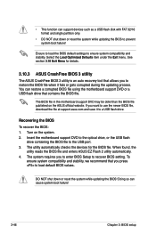
Ensure to load the BIOS default settings to load default BIOS values. When found, the utility reads the BIOS file and enters ASUS EZ Flash 2 utility automatically. 4. You can cause system boot failure! 3-46 Chapter 3: BIOS setup To ensure system compatibility and stability, we recommend that you to enter BIOS Setup to the USB port. 3. DO NOT shut down or reset the system while updating the BIOS to a USB flash drive. Doing so can restore a corrupted BIOS file using the motherboard support DVD or a USB flash drive that allows you...
Ensure to load the BIOS default settings to load default BIOS values. When found, the utility reads the BIOS file and enters ASUS EZ Flash 2 utility automatically. 4. You can cause system boot failure! 3-46 Chapter 3: BIOS setup To ensure system compatibility and stability, we recommend that you to enter BIOS Setup to the USB port. 3. DO NOT shut down or reset the system while updating the BIOS to a USB flash drive. Doing so can restore a corrupted BIOS file using the motherboard support DVD or a USB flash drive that allows you...
User Manual
Page 135
... is not supported under DOS environment. Insert the USB flash drive with the latest BIOS file and BIOS Updater to show the BIOS Boot Device Select Menu. When the ASUS Logo appears, press to the USB port. 2. Please select boot device: SATA: XXXXXXXXXXXXXXXX USB XXXXXXXXXXXXXXXXX UEFI: XXXXXXXXXXXXXXXX Enter Setup ↑ and ↓ to move selection ENTER to select boot device ESC to FreeDOS (http://www.freedos.org)! C:\>d: D:\> ROG MAXIMUS IV GENE-Z/GEN3 3-47 3.10.4 ASUS BIOS Updater The ASUS BIOS Updater allows you can use as...
... is not supported under DOS environment. Insert the USB flash drive with the latest BIOS file and BIOS Updater to show the BIOS Boot Device Select Menu. When the ASUS Logo appears, press to the USB port. 2. Please select boot device: SATA: XXXXXXXXXXXXXXXX USB XXXXXXXXXXXXXXXXX UEFI: XXXXXXXXXXXXXXXX Enter Setup ↑ and ↓ to move selection ENTER to select boot device ESC to FreeDOS (http://www.freedos.org)! C:\>d: D:\> ROG MAXIMUS IV GENE-Z/GEN3 3-47 3.10.4 ASUS BIOS Updater The ASUS BIOS Updater allows you can use as...
User Manual
Page 141
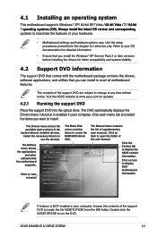
... support DVD to locate the file ASSETUP.EXE from the BIN folder. Click the Contact tab to run the DVD. The Drivers menu shows the available device drivers if the system detects installed devices. Double-click the ASSETUP.EXE to display the ASUS contact information. ASUS MAXIMUS IV GENE-Z/GEN3 4-1 The Manual menu contains the list of the user manual. Use the setup procedures presented in this chapter for reference only. 4.1 Installing an operating system This motherboard supports Windows...
... support DVD to locate the file ASSETUP.EXE from the BIN folder. Click the Contact tab to run the DVD. The Drivers menu shows the available device drivers if the system detects installed devices. Double-click the ASSETUP.EXE to display the ASUS contact information. ASUS MAXIMUS IV GENE-Z/GEN3 4-1 The Manual menu contains the list of the user manual. Use the setup procedures presented in this chapter for reference only. 4.1 Installing an operating system This motherboard supports Windows...
User Manual
Page 165
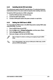
... RAID configuration: 1. Connect the SATA signal cables. 3. Go to [RAID]. 4. Refer to RAID mode, all SATA ports run at RAID mode together. Set the Configure SATA as item to the Main menu > Storage Configuration, and then press . 3. ASUS MAXIMUS IV GENE-Z/GEN3 4-25 4.4.2 Installing Serial ATA hard disks The motherboard supports Serial ATA hard disk drives. Install the SATA hard disks into the drive bays. 2. To do this: 1. Connect a SATA power cable to chipset limitation, when set (s) using SATA HDDs. Due to the power connector on entering and navigating through the BIOS...
... RAID configuration: 1. Connect the SATA signal cables. 3. Go to [RAID]. 4. Refer to RAID mode, all SATA ports run at RAID mode together. Set the Configure SATA as item to the Main menu > Storage Configuration, and then press . 3. ASUS MAXIMUS IV GENE-Z/GEN3 4-25 4.4.2 Installing Serial ATA hard disks The motherboard supports Serial ATA hard disk drives. Install the SATA hard disks into the drive bays. 2. To do this: 1. Connect a SATA power cable to chipset limitation, when set (s) using SATA HDDs. Due to the power connector on entering and navigating through the BIOS...
User Manual
Page 172
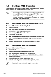
...floppy drive connector. Save changes and exit BIOS. 6. To work around this OS limitation, refer to enter the BIOS setup utility. 3. Press during POST to section 4.5.4 Using a USB floppy disk drive. 4.5.1 Creating a RAID driver disk without entering the OS To create a RAID driver disk without entering the OS: 1. Place the motherboard support DVD into the optical drive. 4. Plug the USB floppy disk drive and insert a floppy disk. 3. Select USB floppy disk drive as the primary boot device. 4. You have to use a USB floppy disk drive when creating a SATA RAID driver disk. • Windows...
...floppy drive connector. Save changes and exit BIOS. 6. To work around this OS limitation, refer to enter the BIOS setup utility. 3. Press during POST to section 4.5.4 Using a USB floppy disk drive. 4.5.1 Creating a RAID driver disk without entering the OS To create a RAID driver disk without entering the OS: 1. Place the motherboard support DVD into the optical drive. 4. Plug the USB floppy disk drive and insert a floppy disk. 3. Select USB floppy disk drive as the primary boot device. 4. You have to use a USB floppy disk drive when creating a SATA RAID driver disk. • Windows...
User Manual
Page 173
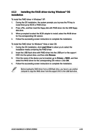
... then insert the floppy disk with RAID driver into the USB port or the support DVD into the USB floppy disk drive. 3. Click the name of the device you to press the F6 key to install third-party SCSI or RAID driver. 2. Click OK. 4. Follow the succeeding screen instructions to complete the installation. Insert the USB flash drive with RAID driver into the optical drive, and then click Browse. 3. ASUS MAXIMUS IV GENE-Z/GEN3 4-33 During the OS installation, the system prompts...
... then insert the floppy disk with RAID driver into the USB port or the support DVD into the USB floppy disk drive. 3. Click the name of the device you to press the F6 key to install third-party SCSI or RAID driver. 2. Click OK. 4. Follow the succeeding screen instructions to complete the installation. Insert the USB flash drive with RAID driver into the optical drive, and then click Browse. 3. ASUS MAXIMUS IV GENE-Z/GEN3 4-33 During the OS installation, the system prompts...
User Manual
Page 174
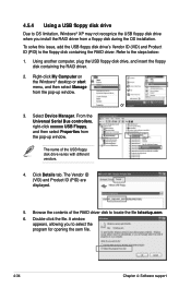
... file. The name of the RAID driver disk to the floppy disk containing the RAID driver. From the Universal Serial Bus controllers, right-click xxxxxx USB Floppy, and then select Properties from a floppy disk during the OS installation. Browse the contents of the USB floppy disk drive varies with different vendors. 4. A window appears, allowing you install the RAID driver from the pop-up window. Select Device Manager. Click Details tab. Using another computer, plug the USB floppy disk drive, and insert the floppy disk...
... file. The name of the RAID driver disk to the floppy disk containing the RAID driver. From the Universal Serial Bus controllers, right-click xxxxxx USB Floppy, and then select Properties from a floppy disk during the OS installation. Browse the contents of the USB floppy disk drive varies with different vendors. 4. A window appears, allowing you install the RAID driver from the pop-up window. Select Device Manager. Click Details tab. Using another computer, plug the USB floppy disk drive, and insert the floppy disk...


