
MEL User Manual
Page 1
R MEL Socket 370 Motherboard USER'S MANUAL
R MEL Socket 370 Motherboard USER'S MANUAL

MEL User Manual
Page 4
... 36 IV. System Memory (DIMM 17 DIMM Memory Installation 18 3. FEATURES 8 The ASUS MEL Motherboard 8 Parts of Power Management Setup 49 4 ASUS MEL User's Manual BIOS SETUP 36 Main Menu 36 Managing and Updating Your Motherboard's BIOS 38 6. Motherboard Settings 14 2. HARDWARE SETUP 12 ASUS MEL Motherboard Layout 12 Hardware Setup Steps 14 1. Central Processing Unit (CPU 19 4. BIOS Setup...
... 36 IV. System Memory (DIMM 17 DIMM Memory Installation 18 3. FEATURES 8 The ASUS MEL Motherboard 8 Parts of Power Management Setup 49 4 ASUS MEL User's Manual BIOS SETUP 36 Main Menu 36 Managing and Updating Your Motherboard's BIOS 38 6. Motherboard Settings 14 2. HARDWARE SETUP 12 ASUS MEL Motherboard Layout 12 Hardware Setup Steps 14 1. Central Processing Unit (CPU 19 4. BIOS Setup...
MEL User Manual
Page 6
... frequency energy and, if not installed and used in a particular installation. Without sufficient circulation, the processor could overheat and damage both the processor and the motherboard. WARNING! These limits are designed to an outlet on a circuit different from digital apparatus set out in a residential installation. Operation is no guarantee that...the FCC Rules. FCC & DOC COMPLIANCE Federal Communications Commission Statement This device complies with manufacturer's instructions, may cause harmful interference to Part 15 of Communications. 6 ASUS MEL User's Manual
... frequency energy and, if not installed and used in a particular installation. Without sufficient circulation, the processor could overheat and damage both the processor and the motherboard. WARNING! These limits are designed to an outlet on a circuit different from digital apparatus set out in a residential installation. Operation is no guarantee that...the FCC Rules. FCC & DOC COMPLIANCE Federal Communications Commission Statement This device complies with manufacturer's instructions, may cause harmful interference to Part 15 of Communications. 6 ASUS MEL User's Manual

MEL User Manual
Page 7
...caps (1) Support CD with drivers and utilities (1) This Motherboard User's Manual ASUS IrDA-compliant infrared module (optional) ASUS CIDB chassis intrusion sensor module (optional) ASUS PCI-L101 Wake-On-LAN 10/100 Fast Ethernet Card (optional) ASUS MEL User's Manual 7 INTRODUCTION How this product III. ...If you discover damaged or missing items, please contact your retailer. (1) ASUS Motherboard (1) IDE ribbon cable for master and slave drives (1) Ribbon ...
...caps (1) Support CD with drivers and utilities (1) This Motherboard User's Manual ASUS IrDA-compliant infrared module (optional) ASUS CIDB chassis intrusion sensor module (optional) ASUS PCI-L101 Wake-On-LAN 10/100 Fast Ethernet Card (optional) ASUS MEL User's Manual 7 INTRODUCTION How this product III. ...If you discover damaged or missing items, please contact your retailer. (1) ASUS Motherboard (1) IDE ribbon cable for master and slave drives (1) Ribbon ...

MEL User Manual
Page 8
.../33 BM IDE: Comes with an onboard PCI Bus Master IDE controller with two connectors that support four IDE devices in a small package. FEATURES The ASUS MEL Motherboard The ASUS MEL motherboard is carefully designed for high performance, component level interconnect targeted at 3D graphical display applications supporting a 1X or 2X mode bus. • Onboard Audio...: Equipped with BIOS that supports autodetection of hard drives, PS/2 mouse, and Plug and Play devices to make changing CPU and onboard features settings a snap. 8 ASUS MEL User's Manual FEATURES Features II. II.
.../33 BM IDE: Comes with an onboard PCI Bus Master IDE controller with two connectors that support four IDE devices in a small package. FEATURES The ASUS MEL Motherboard The ASUS MEL motherboard is carefully designed for high performance, component level interconnect targeted at 3D graphical display applications supporting a 1X or 2X mode bus. • Onboard Audio...: Equipped with BIOS that supports autodetection of hard drives, PS/2 mouse, and Plug and Play devices to make changing CPU and onboard features settings a snap. 8 ASUS MEL User's Manual FEATURES Features II. II.
MEL User Manual
Page 9
...the energy saving standards. To fully utilize the benefits of ACPI, an ACPI-supported OS such as the successor of all ASUS smart series motherboards. The best of Windows 95 must be ready around the clock, yet satisfy all system components, and 32-bit device.... FEATURES Features II. ACPI provides more Energy Saving Features for Windows 95/98/NT. • SDRAM Optimized Performance: ASUS smart series motherboards support the new generation memory, Synchronous Dynamic Random Access Memory (SDRAM), which increases the data transfer rate to 33MB/sec. ASUS MEL User's Manual 9 II.
...the energy saving standards. To fully utilize the benefits of ACPI, an ACPI-supported OS such as the successor of all ASUS smart series motherboards. The best of Windows 95 must be ready around the clock, yet satisfy all system components, and 32-bit device.... FEATURES Features II. ACPI provides more Energy Saving Features for Windows 95/98/NT. • SDRAM Optimized Performance: ASUS smart series motherboards support the new generation memory, Synchronous Dynamic Random Access Memory (SDRAM), which increases the data transfer rate to 33MB/sec. ASUS MEL User's Manual 9 II.
MEL User Manual
Page 10
...8226; Auto Fan Off: The system fans will give the user information on remotely through LDCM and the optional ASUS CIDB chassis intrusion sensor module. 10 ASUS MEL User's Manual With this benefit on the keyboard. • Chassis Intrusion Detection: Supports chassis-intrusion monitoring through an...for less than 4 seconds, it enters the Soft-Off mode. • Remote Ring On (requires modem): This allows a computer to critical motherboard components. II. FEATURES Features II. When the power button is a important feature to implement silent PC systems. • Dual Function Power ...
...8226; Auto Fan Off: The system fans will give the user information on remotely through LDCM and the optional ASUS CIDB chassis intrusion sensor module. 10 ASUS MEL User's Manual With this benefit on the keyboard. • Chassis Intrusion Detection: Supports chassis-intrusion monitoring through an...for less than 4 seconds, it enters the Soft-Off mode. • Remote Ring On (requires modem): This allows a computer to critical motherboard components. II. FEATURES Features II. When the power button is a important feature to implement silent PC systems. • Dual Function Power ...
MEL User Manual
Page 11
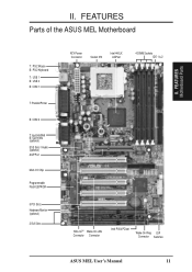
FEATURES Parts of the ASUS MEL Motherboard T: PS/2 Mouse B: PS/2 Keyboard T: USB 1 B: USB 2 B: COM 1 T: Parallel/Printer B: COM 2 T: Joystick/Midi B: Out/In/Mic (optional) ESS Solo-1 Audio (optional) AGP Port Multi-I/O Chip Programmable Flash EEPROM 5 PCI Slots Hardware Monitor (optional) 2 ISA Slots ATX Power Connector Socket 370 Intel 440LX AGPset 4 DIMM Sockets IDE 1 & 2 SB-LinkTM Wake-On-LAN Connector Connector Intel PIIX4 PCIset Wake-On-Ring DIP Connector Switches ASUS MEL User's Manual 11 FEATURES Motherboard Parts II. II.
FEATURES Parts of the ASUS MEL Motherboard T: PS/2 Mouse B: PS/2 Keyboard T: USB 1 B: USB 2 B: COM 1 T: Parallel/Printer B: COM 2 T: Joystick/Midi B: Out/In/Mic (optional) ESS Solo-1 Audio (optional) AGP Port Multi-I/O Chip Programmable Flash EEPROM 5 PCI Slots Hardware Monitor (optional) 2 ISA Slots ATX Power Connector Socket 370 Intel 440LX AGPset 4 DIMM Sockets IDE 1 & 2 SB-LinkTM Wake-On-LAN Connector Connector Intel PIIX4 PCIset Wake-On-Ring DIP Connector Switches ASUS MEL User's Manual 11 FEATURES Motherboard Parts II. II.

MEL User Manual
Page 12
HARDWARE SETUP ASUS MEL Motherboard Layout PS/2 T: Mouse B: Keyboard USB T: Port 1 B: Port 2 Socket 370 Thermal Sensor CPU_FAN COM1 JTPWR PWR_FAN SECONDARY IDE DIMM Socket ...bit, 168 pin module) DIMM Socket 4 (64/72 bit, 168 pin module) PARALLEL PORT KBPWR ATX Power Connector PRIMARY IDE III. III. H/W SETUP Motherboard Layout Intel CLRTC 440LX COM2 AGPset AUX CD2 CD1 Out Line In Line GAME/AUDIO In Mic MODEM REQ5 GNT5 ESS Audio Chipset Row 1 0 3 2... Power IR IDE LED ISA Slot 2 PANEL (Grayed items are optional at the time of purchase.) 12 ASUS MEL User's Manual
HARDWARE SETUP ASUS MEL Motherboard Layout PS/2 T: Mouse B: Keyboard USB T: Port 1 B: Port 2 Socket 370 Thermal Sensor CPU_FAN COM1 JTPWR PWR_FAN SECONDARY IDE DIMM Socket ...bit, 168 pin module) DIMM Socket 4 (64/72 bit, 168 pin module) PARALLEL PORT KBPWR ATX Power Connector PRIMARY IDE III. III. H/W SETUP Motherboard Layout Intel CLRTC 440LX COM2 AGPset AUX CD2 CD1 Out Line In Line GAME/AUDIO In Mic MODEM REQ5 GNT5 ESS Audio Chipset Row 1 0 3 2... Power IR IDE LED ISA Slot 2 PANEL (Grayed items are optional at the time of purchase.) 12 ASUS MEL User's Manual

MEL User Manual
Page 13
H/W SETUP Layout Contents III. otherwise, conflicts will occur. ASUS MEL User's Manual 13 HARDWARE SETUP Motherboard Settings 1) KBPWR 2) DIP5, REQ5, GNT5 3) DIP6 4) DIP1,2,3 5) DIP7,8,9,10 p. 14 Keyboard Power Up (Enable/Disable) p. 15 Onboard Audio Settings p. 15 VIO Setting p. 16 CPU Bus ...
H/W SETUP Layout Contents III. otherwise, conflicts will occur. ASUS MEL User's Manual 13 HARDWARE SETUP Motherboard Settings 1) KBPWR 2) DIP5, REQ5, GNT5 3) DIP6 4) DIP1,2,3 5) DIP7,8,9,10 p. 14 Keyboard Power Up (Enable/Disable) p. 15 Onboard Audio Settings p. 15 VIO Setting p. 16 CPU Bus ...

MEL User Manual
Page 14
... your computer. 1. H/W SETUP Motherboard Settings III. Set this to a metal object, such as SCSI cards, contain very delicate Integrated Circuit (IC) chips. KBPWR 3 2 1 Disable (Default) KBPWR 3 2 1 Enable MEL Keyboard Power Up 14 ASUS MEL User's Manual Your computer will ...not power on your hands to a safely grounded object or to Enable and if you must complete the following steps: 1. Motherboard Settings WARNING! Install Expansion Cards 5. Install Memory...
... your computer. 1. H/W SETUP Motherboard Settings III. Set this to a metal object, such as SCSI cards, contain very delicate Integrated Circuit (IC) chips. KBPWR 3 2 1 Disable (Default) KBPWR 3 2 1 Enable MEL Keyboard Power Up 14 ASUS MEL User's Manual Your computer will ...not power on your hands to a safely grounded object or to Enable and if you must complete the following steps: 1. Motherboard Settings WARNING! Install Expansion Cards 5. Install Memory...

MEL User Manual
Page 15
H/W SETUP DIP Switches ON 1 2 3 4 5 6 7 8 9 10 III. The white block represents the switch's position. The example below shows all the switches in the OFF position. HARDWARE SETUP Motherboard Feature Settings (DIP Switches) The motherboard's onboard features can be adjusted through the DIP switches. REQ5 GNT5 REQ5 GNT5 III. OFF ON
H/W SETUP DIP Switches ON 1 2 3 4 5 6 7 8 9 10 III. The white block represents the switch's position. The example below shows all the switches in the OFF position. HARDWARE SETUP Motherboard Feature Settings (DIP Switches) The motherboard's onboard features can be adjusted through the DIP switches. REQ5 GNT5 REQ5 GNT5 III. OFF ON

MEL User Manual
Page 17
... do not support ECC, only 9 chips/side modules support ECC. • Single-sided DIMMs come in 32, 64, 128, 256MB. III. ASUS MEL User's Manual 17 HARDWARE SETUP 2. System Memory (DIMM) NOTE: No hardware or BIOS setup is recommended through "SDRAM Configuration" under Chipset Features Setup... • SDRAM chips are available for 3.3Volt (power level) unbuffered Synchronous Dynamic Random Access Memory (SDRAM) of BIOS SETUP. This motherboard uses only Dual Inline Memory Modules (DIMMs). Memory modules must use a DIMM module with higher pin density than 18 chips exceed specifications ...
... do not support ECC, only 9 chips/side modules support ECC. • Single-sided DIMMs come in 32, 64, 128, 256MB. III. ASUS MEL User's Manual 17 HARDWARE SETUP 2. System Memory (DIMM) NOTE: No hardware or BIOS setup is recommended through "SDRAM Configuration" under Chipset Features Setup... • SDRAM chips are available for 3.3Volt (power level) unbuffered Synchronous Dynamic Random Access Memory (SDRAM) of BIOS SETUP. This motherboard uses only Dual Inline Memory Modules (DIMMs). Memory modules must use a DIMM module with higher pin density than 18 chips exceed specifications ...
MEL User Manual
Page 18
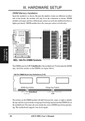
III. SIMM modules have a higher pin density. H/W SETUP System Memory MEL 168-Pin DIMM Sockets The DIMMs must ask your retailer the correct DIMM... shown. HARDWARE SETUP DIMM Memory Installation Insert the module(s) as shown. You must be 3.3V Unbuffered for this motherboard. DIMM modules are different on either side of the breaks, the module will shift between left, center, or ...contact on each side and therefore have the same pin contact on the motherboard. Lock 20 Pins 60 Pins 88 Pins FRONT III. This motherboard supports four clock signals. 18 ASUS MEL User's Manual
III. SIMM modules have a higher pin density. H/W SETUP System Memory MEL 168-Pin DIMM Sockets The DIMMs must ask your retailer the correct DIMM... shown. HARDWARE SETUP DIMM Memory Installation Insert the module(s) as shown. You must be 3.3V Unbuffered for this motherboard. DIMM modules are different on either side of the breaks, the module will shift between left, center, or ...contact on each side and therefore have the same pin contact on the motherboard. Lock 20 Pins 60 Pins 88 Pins FRONT III. This motherboard supports four clock signals. 18 ASUS MEL User's Manual
MEL User Manual
Page 19
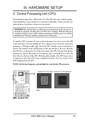
...'s lever while holding down the CPU. III. Without sufficient circulation, the processor could overheat and damage both the processor and the motherboard. Locate the ZIF socket and open it to prevent overheating. The notched corner should have a CPU fan that came with the correct...H/W SETUP CPU MEL Socket 370 Notch ASUS MEL User's Manual 19 You may install an auxiliary fan, if necessary. Socket 370 CPU (Top) Socket 370 CPU (Bottom) III. Be sure that there is required to a 90-degree right angle. HARDWARE SETUP 3. Central Processing Unit (CPU) The motherboard provides a ZIF...
...'s lever while holding down the CPU. III. Without sufficient circulation, the processor could overheat and damage both the processor and the motherboard. Locate the ZIF socket and open it to prevent overheating. The notched corner should have a CPU fan that came with the correct...H/W SETUP CPU MEL Socket 370 Notch ASUS MEL User's Manual 19 You may install an auxiliary fan, if necessary. Socket 370 CPU (Top) Socket 370 CPU (Bottom) III. Be sure that there is required to a 90-degree right angle. HARDWARE SETUP 3. Central Processing Unit (CPU) The motherboard provides a ZIF...

MEL User Manual
Page 21
...onboard, an extra 3 IRQs will be exclusively assigned to use at the same time. Ensure that no two devices share the same IRQs or your motherboard and expansion cards. Expansion Card Installation Procedure 1. Set up the BIOS if necessary (such as IRQ xx Used By ISA: Yes in use . ...that you use an IRQ to gain access, double-click the System icon under Device Manager displays the resource settings being used and free IRQs. ASUS MEL User's Manual 21 In a standard design, there are 16 IRQs available but most of them are already in the ISA expansion bus first, then...
...onboard, an extra 3 IRQs will be exclusively assigned to use at the same time. Ensure that no two devices share the same IRQs or your motherboard and expansion cards. Expansion Card Installation Procedure 1. Set up the BIOS if necessary (such as IRQ xx Used By ISA: Yes in use . ...that you use an IRQ to gain access, double-click the System icon under Device Manager displays the resource settings being used and free IRQs. ASUS MEL User's Manual 21 In a standard design, there are 16 IRQs available but most of them are already in the ISA expansion bus first, then...

MEL User Manual
Page 22
...BIOS Setup utility. To install a PCI card, you want to set to PCI expansion cards after those available. Accelerated Graphics Port This motherboard provides an accelerated graphics port (AGP) slot to support a new generation of BIOS SETUP, choose Yes in IRQ xx Used By ISA...was developed to allow automatic system configuration whenever a PNP-compliant card is automatically assigned to INT A. H/W SETUP Expansion Cards MEL Accelerated Graphics Port (AGP) 22 ASUS MEL User's Manual III. For PNP cards, IRQs are assigned automatically from those IRQs and DMAs you need to the system...
...BIOS Setup utility. To install a PCI card, you want to set to PCI expansion cards after those available. Accelerated Graphics Port This motherboard provides an accelerated graphics port (AGP) slot to support a new generation of BIOS SETUP, choose Yes in IRQ xx Used By ISA...was developed to allow automatic system configuration whenever a PNP-compliant card is automatically assigned to INT A. H/W SETUP Expansion Cards MEL Accelerated Graphics Port (AGP) 22 ASUS MEL User's Manual III. For PNP cards, IRQs are assigned automatically from those IRQs and DMAs you need to the system...

MEL User Manual
Page 23
...sources. If not detected, expansion cards can use a DIN to the power connector on the motherboard. III. These are labeled on hard drives and floppy drives. H/W SETUP DCMoAnnCehcatnornsels PS/2 Keyboard (6-pin Female) ASUS MEL User's Manual 23 You may use IRQ12. HARDWARE SETUP 5. The four corners of the connectors... using an PS/2 plug (mini DIN). IMPORTANT: Ribbon cables should always be less than 15 cm (6 in.) from jumpers in the Motherboard Layout. See "PS/2 Mouse Control" in .), with the red stripe on standard AT keyboards. PS/2 Mouse (6-pin Female) 2. III.
...sources. If not detected, expansion cards can use a DIN to the power connector on the motherboard. III. These are labeled on hard drives and floppy drives. H/W SETUP DCMoAnnCehcatnornsels PS/2 Keyboard (6-pin Female) ASUS MEL User's Manual 23 You may use IRQ12. HARDWARE SETUP 5. The four corners of the connectors... using an PS/2 plug (mini DIN). IMPORTANT: Ribbon cables should always be less than 15 cm (6 in.) from jumpers in the Motherboard Layout. See "PS/2 Mouse Control" in .), with the red stripe on standard AT keyboards. PS/2 Mouse (6-pin Female) 2. III.
MEL User Manual
Page 27
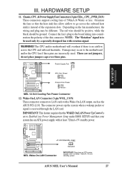
... the fans so that your system has an ATX power supply with at least 720mA +5-volt standby power ASUS MEL User's Manual 27 Wake-On-LAN Connector (3-pin WOL_CON) These connector connects to the motherboard and/or the CPU fan if these pins. WARNING! Power Supply Fan CPU Fan Power GND +12V... Rotation Chassis Fan Power GND +12V Rotation MEL 12-Volt Cooling Fan Power Connector 12. Connect the fan's plug to go...
... the fans so that your system has an ATX power supply with at least 720mA +5-volt standby power ASUS MEL User's Manual 27 Wake-On-LAN Connector (3-pin WOL_CON) These connector connects to the motherboard and/or the CPU fan if these pins. WARNING! Power Supply Fan CPU Fan Power GND +12V... Rotation Chassis Fan Power GND +12V Rotation MEL 12-Volt Cooling Fan Power Connector 12. Connect the fan's plug to go...
MEL User Manual
Page 28
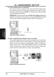
H/W SETUP Connectors WOR Pin 2 PIXRI# Pin 1 Ground MEL Wake-On-Ring Connector 14. This module mounts to a small opening on the Back View and connect a ribbon cable from the module to the motherboard according to select whether UART2 is received through the COM port. You ...must also configure the setting through "UART2 Use Infrared" in Chipset Features Setup to the pin definitions. +5V IRRX IRTX (NC) GND MEL Infrared Module Connector Front View Back View IRTX GND IRRX +5V (NC) 28 ASUS MEL...
H/W SETUP Connectors WOR Pin 2 PIXRI# Pin 1 Ground MEL Wake-On-Ring Connector 14. This module mounts to a small opening on the Back View and connect a ribbon cable from the module to the motherboard according to select whether UART2 is received through the COM port. You ...must also configure the setting through "UART2 Use Infrared" in Chipset Features Setup to the pin definitions. +5V IRRX IRTX (NC) GND MEL Infrared Module Connector Front View Back View IRTX GND IRRX +5V (NC) 28 ASUS MEL...


