
MEL User Manual
Page 1
R MEL Socket 370 Motherboard USER'S MANUAL
R MEL Socket 370 Motherboard USER'S MANUAL
MEL User Manual
Page 2
....tw or through any means, except documentation kept by the third digit in the manual revision number. Product Name: ASUS MEL Manual Revision: 1.01 E335 Release Date: March 1999 2 ASUS MEL User's Manual Copyright © 1999 ASUSTeK COMPUTER INC. IN NO EVENT SHALL ASUS, ITS DIRECTORS, OFFICERS, EMPLOYEES OR AGENTS BE LIABLE FOR ANY INDIRECT, SPECIAL, INCIDENTAL, OR...
....tw or through any means, except documentation kept by the third digit in the manual revision number. Product Name: ASUS MEL Manual Revision: 1.01 E335 Release Date: March 1999 2 ASUS MEL User's Manual Copyright © 1999 ASUSTeK COMPUTER INC. IN NO EVENT SHALL ASUS, ITS DIRECTORS, OFFICERS, EMPLOYEES OR AGENTS BE LIABLE FOR ANY INDIRECT, SPECIAL, INCIDENTAL, OR...

MEL User Manual
Page 3
...-2-2894-3447 ext. 701 Fax: +886-2-2895-9254 Email: tsd@asus.com.tw Newsgroup: news2.asus.com.tw WWW: www.asus.com.tw FTP: ftp.asus.com.tw/pub/ASUS ASUS COMPUTER INTERNATIONAL (America) Marketing Address: 6737 Mowry Avenue, Mowry Business ...ASUS ASUS COMPUTER GmbH (Europe) Marketing Address: Harkort Str. 25, 40880 Ratingen, BRD, Germany Telephone: 49-2102-445011 Fax: 49-2102-442066 Email: [email protected] Technical Support Hotline: 49-2102-499712 BBS: 49-2102-448690 Email: [email protected] WWW: www.asuscom.de FTP: ftp.asuscom.de/pub/ASUSCOM ASUS MEL User's Manual...
...-2-2894-3447 ext. 701 Fax: +886-2-2895-9254 Email: tsd@asus.com.tw Newsgroup: news2.asus.com.tw WWW: www.asus.com.tw FTP: ftp.asus.com.tw/pub/ASUS ASUS COMPUTER INTERNATIONAL (America) Marketing Address: 6737 Mowry Avenue, Mowry Business ...ASUS ASUS COMPUTER GmbH (Europe) Marketing Address: Harkort Str. 25, 40880 Ratingen, BRD, Germany Telephone: 49-2102-445011 Fax: 49-2102-442066 Email: [email protected] Technical Support Hotline: 49-2102-499712 BBS: 49-2102-448690 Email: [email protected] WWW: www.asuscom.de FTP: ftp.asuscom.de/pub/ASUSCOM ASUS MEL User's Manual...

MEL User Manual
Page 4
... 8 Parts of Power Management Setup 49 4 ASUS MEL User's Manual External Connectors 23 The ASUS CIDB Chassis Sensor 32 Setting up the ASUS CIDB 33 Using the ASUS CIDB 33 ASUS CIDB Additional Considerations 34 Power Connection Procedures 35 Flash Memory Writer Utility 36 IV. BIOS ...Setup 46 Details of Chipset Features Setup 46 Power Management Setup 49 Details of the ASUS MEL Motherboard 11 III. INTRODUCTION 7 How this manual is organized 7 Item Checklist 7 II. HARDWARE SETUP 12 ASUS MEL Motherboard Layout 12 Hardware Setup Steps 14 1. Central Processing Unit (CPU 19 4....
... 8 Parts of Power Management Setup 49 4 ASUS MEL User's Manual External Connectors 23 The ASUS CIDB Chassis Sensor 32 Setting up the ASUS CIDB 33 Using the ASUS CIDB 33 ASUS CIDB Additional Considerations 34 Power Connection Procedures 35 Flash Memory Writer Utility 36 IV. BIOS ...Setup 46 Details of Chipset Features Setup 46 Power Management Setup 49 Details of the ASUS MEL Motherboard 11 III. INTRODUCTION 7 How this manual is organized 7 Item Checklist 7 II. HARDWARE SETUP 12 ASUS MEL Motherboard Layout 12 Hardware Setup Steps 14 1. Central Processing Unit (CPU 19 4....
MEL User Manual
Page 5
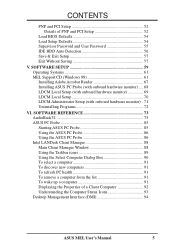
... 55 IDE HDD Auto Detection 56 Save & Exit Setup 57 Exit Without Saving 57 V. SOFTWARE SETUP 59 Operating Systems 61 MEL Support CD (Windows 98 61 Installing Adobe Acrobat Reader 67 Installing ASUS PC Probe (with onboard hardware monitor) .... 68 LDCM Local Setup (with onboard hardware monitor 69 LDCM Local Setup 70... Programs 72 VI. CONTENTS PNP and PCI Setup 52 Details of a Client Computer 92 Understanding the Computer Status Icons 93 Desktop Management Interface (DMI 94 ASUS MEL User's Manual 5
... 55 IDE HDD Auto Detection 56 Save & Exit Setup 57 Exit Without Saving 57 V. SOFTWARE SETUP 59 Operating Systems 61 MEL Support CD (Windows 98 61 Installing Adobe Acrobat Reader 67 Installing ASUS PC Probe (with onboard hardware monitor) .... 68 LDCM Local Setup (with onboard hardware monitor 69 LDCM Local Setup 70... Programs 72 VI. CONTENTS PNP and PCI Setup 52 Details of a Client Computer 92 Understanding the Computer Status Icons 93 Desktop Management Interface (DMI 94 ASUS MEL User's Manual 5
MEL User Manual
Page 6
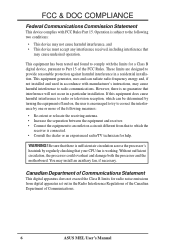
... apparatus does not exceed the Class B limits for radio noise emissions from that may install an auxiliary fan, if necessary. Canadian Department of Communications. 6 ASUS MEL User's Manual Be sure that there is encouraged to try to correct the interference by regularly checking that interference will not occur in accordance with FCC Rules...
... apparatus does not exceed the Class B limits for radio noise emissions from that may install an auxiliary fan, if necessary. Canadian Department of Communications. 6 ASUS MEL User's Manual Be sure that there is encouraged to try to correct the interference by regularly checking that interference will not occur in accordance with FCC Rules...

MEL User Manual
Page 7
.... I . Software Reference Reference material for (1) 5.25" and (2) 3.5" floppy disk drives (1) Bag of spare jumper caps (1) Support CD with drivers and utilities (1) This Motherboard User's Manual ASUS IrDA-compliant infrared module (optional) ASUS CIDB chassis intrusion sensor module (optional) ASUS PCI-L101 Wake-On-LAN 10/100 Fast Ethernet Card (optional) ASUS MEL User's Manual 7 INTRODUCTION Sections/Checklist I.
.... I . Software Reference Reference material for (1) 5.25" and (2) 3.5" floppy disk drives (1) Bag of spare jumper caps (1) Support CD with drivers and utilities (1) This Motherboard User's Manual ASUS IrDA-compliant infrared module (optional) ASUS CIDB chassis intrusion sensor module (optional) ASUS PCI-L101 Wake-On-LAN 10/100 Fast Ethernet Card (optional) ASUS MEL User's Manual 7 INTRODUCTION Sections/Checklist I.

MEL User Manual
Page 8
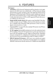
... and system voltages, temperatures, and fan status through the onboard hardware ASIC and bundled LDCM or ASUS PC Probe. • Wake-On-LAN Connector: Supports Wake-On-LAN activity through an optional ASUS PCI-L101 Fast Ethernet card or a similar ethernet card. • SB-Link™: Features ...PC66compliant SDRAMs (8, 16, 32, 64, 128, or 256MB) up to -access function switches make changing CPU and onboard features settings a snap. 8 ASUS MEL User's Manual II. FEATURES The ASUS MEL Motherboard The ASUS MEL motherboard is carefully designed for Socket 370 and packaged in a small package.
... and system voltages, temperatures, and fan status through the onboard hardware ASIC and bundled LDCM or ASUS PC Probe. • Wake-On-LAN Connector: Supports Wake-On-LAN activity through an optional ASUS PCI-L101 Fast Ethernet card or a similar ethernet card. • SB-Link™: Features ...PC66compliant SDRAMs (8, 16, 32, 64, 128, or 256MB) up to -access function switches make changing CPU and onboard features settings a snap. 8 ASUS MEL User's Manual II. FEATURES The ASUS MEL Motherboard The ASUS MEL motherboard is carefully designed for Socket 370 and packaged in a small package.
MEL User Manual
Page 9
...managing all the energy saving standards. ACPI provides more Energy Saving Features for Windows 95/98/NT. • SDRAM Optimized Performance: ASUS smart series motherboards support the new generation memory, Synchronous Dynamic Random Access Memory (SDRAM), which increases the data transfer rate to 528MB/s... is compatible with existing ATA-2 IDE specifications so there is also imple- ASUS MEL User's Manual 9 To fully utilize the benefits of ACPI, an ACPI-supported OS such as the successor of all ASUS smart series motherboards. The best of Windows 95 must be ready around the...
...managing all the energy saving standards. ACPI provides more Energy Saving Features for Windows 95/98/NT. • SDRAM Optimized Performance: ASUS smart series motherboards support the new generation memory, Synchronous Dynamic Random Access Memory (SDRAM), which increases the data transfer rate to 528MB/s... is compatible with existing ATA-2 IDE specifications so there is also imple- ASUS MEL User's Manual 9 To fully utilize the benefits of ACPI, an ACPI-supported OS such as the successor of all ASUS smart series motherboards. The best of Windows 95 must be ready around the...
MEL User Manual
Page 10
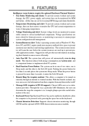
... or disabled to allow the computer to be powered on by pressing the space bar on remotely through LDCM and the optional ASUS CIDB chassis intrusion sensor module. 10 ASUS MEL User's Manual Pushing the power button for RPM and failure. FEATURES Intelligence (some features require the optional Hardware/Thermal Monitor) • Fan Status...
... or disabled to allow the computer to be powered on by pressing the space bar on remotely through LDCM and the optional ASUS CIDB chassis intrusion sensor module. 10 ASUS MEL User's Manual Pushing the power button for RPM and failure. FEATURES Intelligence (some features require the optional Hardware/Thermal Monitor) • Fan Status...
MEL User Manual
Page 11
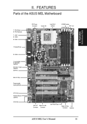
FEATURES Parts of the ASUS MEL Motherboard T: PS/2 Mouse B: PS/2 Keyboard T: USB 1 B: USB 2 B: COM 1 T: Parallel/Printer B: COM 2 T: Joystick/Midi B: Out/In/Mic (optional) ESS Solo-1 Audio (optional) AGP Port Multi-I/O Chip Programmable Flash EEPROM 5 PCI Slots Hardware Monitor (optional) 2 ISA Slots ATX Power Connector Socket 370 Intel 440LX AGPset 4 DIMM Sockets IDE 1 & 2 SB-LinkTM Wake-On-LAN Connector Connector Intel PIIX4 PCIset Wake-On-Ring DIP Connector Switches ASUS MEL User's Manual 11 FEATURES Motherboard Parts II. II.
FEATURES Parts of the ASUS MEL Motherboard T: PS/2 Mouse B: PS/2 Keyboard T: USB 1 B: USB 2 B: COM 1 T: Parallel/Printer B: COM 2 T: Joystick/Midi B: Out/In/Mic (optional) ESS Solo-1 Audio (optional) AGP Port Multi-I/O Chip Programmable Flash EEPROM 5 PCI Slots Hardware Monitor (optional) 2 ISA Slots ATX Power Connector Socket 370 Intel 440LX AGPset 4 DIMM Sockets IDE 1 & 2 SB-LinkTM Wake-On-LAN Connector Connector Intel PIIX4 PCIset Wake-On-Ring DIP Connector Switches ASUS MEL User's Manual 11 FEATURES Motherboard Parts II. II.

MEL User Manual
Page 12
HARDWARE SETUP ASUS MEL Motherboard Layout PS/2 T: Mouse B: Keyboard USB T: Port 1 B: Port 2 Socket 370 Thermal Sensor CPU_FAN COM1 JTPWR PWR_FAN SECONDARY IDE DIMM Socket 1 (64/72 bit, 168 pin ... Slot 1 CHASIS WOR CR2032 3V Lithium Cell CMOS Power IR IDE LED ISA Slot 2 PANEL (Grayed items are optional at the time of purchase.) 12 ASUS MEL User's Manual III.
HARDWARE SETUP ASUS MEL Motherboard Layout PS/2 T: Mouse B: Keyboard USB T: Port 1 B: Port 2 Socket 370 Thermal Sensor CPU_FAN COM1 JTPWR PWR_FAN SECONDARY IDE DIMM Socket 1 (64/72 bit, 168 pin ... Slot 1 CHASIS WOR CR2032 3V Lithium Cell CMOS Power IR IDE LED ISA Slot 2 PANEL (Grayed items are optional at the time of purchase.) 12 ASUS MEL User's Manual III.

MEL User Manual
Page 13
III. H/W SETUP Layout Contents III. ASUS MEL User's Manual 13 HARDWARE SETUP Motherboard Settings 1) KBPWR 2) DIP5, REQ5, GNT5 3) DIP6 4) DIP1,2,3 5) DIP7,8,9,10 p. 14 Keyboard Power Up (Enable/Disable) p. 15 Onboard Audio Settings p. 15 VIO ...
III. H/W SETUP Layout Contents III. ASUS MEL User's Manual 13 HARDWARE SETUP Motherboard Settings 1) KBPWR 2) DIP5, REQ5, GNT5 3) DIP6 4) DIP1,2,3 5) DIP7,8,9,10 p. 14 Keyboard Power Up (Enable/Disable) p. 15 Onboard Audio Settings p. 15 VIO ...

MEL User Manual
Page 14
... Disable because not all computers have one, touch both of your computer when working on the inside. 2. KBPWR 3 2 1 Disable (Default) KBPWR 3 2 1 Enable MEL Keyboard Power Up 14 ASUS MEL User's Manual Install Expansion Cards 5. If you wish to use your computer. 1. Check Motherboard Settings 2. Setup the BIOS Software 1. Set this to Enable and if...
... Disable because not all computers have one, touch both of your computer when working on the inside. 2. KBPWR 3 2 1 Disable (Default) KBPWR 3 2 1 Enable MEL Keyboard Power Up 14 ASUS MEL User's Manual Install Expansion Cards 5. If you wish to use your computer. 1. Check Motherboard Settings 2. Setup the BIOS Software 1. Set this to Enable and if...

MEL User Manual
Page 15
REQ5 GNT5 REQ5 GNT5 III. The example below shows all the switches in the OFF position. The white block represents the switch's position. HARDWARE SETUP Motherboard Feature Settings (DIP Switches) The motherboard's onboard features can be adjusted through the DIP switches. H/W SETUP DIP Switches ON 1 2 3 4 5 6 7 8 9 10 III. OFF ON
REQ5 GNT5 REQ5 GNT5 III. The example below shows all the switches in the OFF position. The white block represents the switch's position. HARDWARE SETUP Motherboard Feature Settings (DIP Switches) The motherboard's onboard features can be adjusted through the DIP switches. H/W SETUP DIP Switches ON 1 2 3 4 5 6 7 8 9 10 III. OFF ON

MEL User Manual
Page 16
...ON] [ON] [ON] [OFF] [OFF] [OFF] [OFF] [ON] [ON] [OFF] [OFF] [ON] [OFF] [ON] [OFF] [ON] 16 ASUS MEL User's Manual CPU/AGP → 66.8MHz 68.5MHz 72MHz 75MHz PCI BUS → 33.4MHz 34.2MHz 36MHz 37.5MHz ON 1 2 3 4 5 6 7 8 9 10...7 8 9 10 ON 1 2 3 4 5 6 7 8 9 10 6.0x(6/1) 6.5x(13/2) 7.0x(7/1) 7.5x(15/2) 8.0x(8/1) ON 1 2 3 4 5 6 7 8 9 10 ON 1 2 3 4 5 6 7 8 9 10 ON 1 2 3 4 5 6 7 8 9 10 ON 1 2 3 4 5 6 7 8 9 10 ON 1 2 3 4 5 6 7 8 9 10 MEL CPU : BUS Frequency Multiple Set the function switches by the Internal speed of the CPU's External frequency (or BUS Clock). The BUS Clock times the...
...ON] [ON] [ON] [OFF] [OFF] [OFF] [OFF] [ON] [ON] [OFF] [OFF] [ON] [OFF] [ON] [OFF] [ON] 16 ASUS MEL User's Manual CPU/AGP → 66.8MHz 68.5MHz 72MHz 75MHz PCI BUS → 33.4MHz 34.2MHz 36MHz 37.5MHz ON 1 2 3 4 5 6 7 8 9 10...7 8 9 10 ON 1 2 3 4 5 6 7 8 9 10 6.0x(6/1) 6.5x(13/2) 7.0x(7/1) 7.5x(15/2) 8.0x(8/1) ON 1 2 3 4 5 6 7 8 9 10 ON 1 2 3 4 5 6 7 8 9 10 ON 1 2 3 4 5 6 7 8 9 10 ON 1 2 3 4 5 6 7 8 9 10 ON 1 2 3 4 5 6 7 8 9 10 MEL CPU : BUS Frequency Multiple Set the function switches by the Internal speed of the CPU's External frequency (or BUS Clock). The BUS Clock times the...

MEL User Manual
Page 17
... the chipset's Error Checking and Correction (ECC) feature, you must have 18 chips or less. This motherboard uses only Dual Inline Memory Modules (DIMMs). ASUS MEL User's Manual 17 Memory modules with higher pin density than 18 chips exceed specifications and may cause unstable operation. Memory modules must use a DIMM module with memory...
... the chipset's Error Checking and Correction (ECC) feature, you must have 18 chips or less. This motherboard uses only Dual Inline Memory Modules (DIMMs). ASUS MEL User's Manual 17 Memory modules with higher pin density than 18 chips exceed specifications and may cause unstable operation. Memory modules must use a DIMM module with memory...
MEL User Manual
Page 18
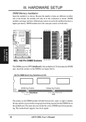
.... HARDWARE SETUP DIMM Memory Installation Insert the module(s) as shown. Because the number of pins are longer and have a higher pin density. H/W SETUP System Memory MEL 168-Pin DIMM Sockets The DIMMs must ask your retailer the correct DIMM type before purchasing. DIMM modules are different on each side and therefore... type and also to prevent the wrong type from being inserted into the DIMM slot on both sides. This motherboard supports four clock signals. 18 ASUS MEL User's Manual III.
.... HARDWARE SETUP DIMM Memory Installation Insert the module(s) as shown. Because the number of pins are longer and have a higher pin density. H/W SETUP System Memory MEL 168-Pin DIMM Sockets The DIMMs must ask your retailer the correct DIMM type before purchasing. DIMM modules are different on each side and therefore... type and also to prevent the wrong type from being inserted into the DIMM slot on both sides. This motherboard supports four clock signals. 18 ASUS MEL User's Manual III.
MEL User Manual
Page 19
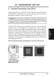
... motherboard provides a ZIF Socket 370. You may install an auxiliary fan, if necessary. you turn off your CPU fan is working. H/W SETUP CPU MEL Socket 370 Notch ASUS MEL User's Manual 19 NOTE: Set the bus frequency and multiple for your system. WARNING! The notched corner should have a CPU fan that your system and...
... motherboard provides a ZIF Socket 370. You may install an auxiliary fan, if necessary. you turn off your CPU fan is working. H/W SETUP CPU MEL Socket 370 Notch ASUS MEL User's Manual 19 NOTE: Set the bus frequency and multiple for your system. WARNING! The notched corner should have a CPU fan that your system and...
MEL User Manual
Page 20
HARDWARE SETUP (This page was intentionally left blank.) III. H/W SETUP CPU 20 ASUS MEL User's Manual III.
HARDWARE SETUP (This page was intentionally left blank.) III. H/W SETUP CPU 20 ASUS MEL User's Manual III.


