MEL User Manual
Page 2
... Corporation. • Windows and MS-DOS are registered trademarks of Adobe Systems Incorporated. Product Name: ASUS MEL Manual Revision: 1.01 E335 Release Date: March 1999 2 ASUS MEL User's Manual The product name and revision number are registered trademarks of Microsoft Corporation. • Adobe...FITNESS FOR A PARTICULAR PURPOSE. For previous or updated manuals, BIOS, drivers, or product release information, contact ASUS at http://www.asus.com.tw or through any means, except documentation kept by ASUS; SPECIFICATIONS AND INFORMATION CONTAINED IN THIS MANUAL ARE FURNISHED FOR ...
... Corporation. • Windows and MS-DOS are registered trademarks of Adobe Systems Incorporated. Product Name: ASUS MEL Manual Revision: 1.01 E335 Release Date: March 1999 2 ASUS MEL User's Manual The product name and revision number are registered trademarks of Microsoft Corporation. • Adobe...FITNESS FOR A PARTICULAR PURPOSE. For previous or updated manuals, BIOS, drivers, or product release information, contact ASUS at http://www.asus.com.tw or through any means, except documentation kept by ASUS; SPECIFICATIONS AND INFORMATION CONTAINED IN THIS MANUAL ARE FURNISHED FOR ...

MEL User Manual
Page 4
INTRODUCTION 7 How this manual is organized 7 Item Checklist 7 II. HARDWARE SETUP 12 ASUS MEL Motherboard Layout 12 Hardware Setup Steps 14 1. Expansion Cards 21 Expansion Card Installation Procedure 21 Assigning IRQs for Expansion Cards 21 Assigning ... Load Defaults 40 Standard CMOS Setup 40 Details of Standard CMOS Setup 40 BIOS Features Setup 43 Details of BIOS Features Setup 43 Chipset Features Setup 46 Details of Chipset Features Setup 46 Power Management Setup 49 Details of the ASUS MEL Motherboard 11 III. CONTENTS I. Central Processing Unit (CPU 19 4. FEATURES...
INTRODUCTION 7 How this manual is organized 7 Item Checklist 7 II. HARDWARE SETUP 12 ASUS MEL Motherboard Layout 12 Hardware Setup Steps 14 1. Expansion Cards 21 Expansion Card Installation Procedure 21 Assigning IRQs for Expansion Cards 21 Assigning ... Load Defaults 40 Standard CMOS Setup 40 Details of Standard CMOS Setup 40 BIOS Features Setup 43 Details of BIOS Features Setup 43 Chipset Features Setup 46 Details of Chipset Features Setup 46 Power Management Setup 49 Details of the ASUS MEL Motherboard 11 III. CONTENTS I. Central Processing Unit (CPU 19 4. FEATURES...
MEL User Manual
Page 5
...Computer 92 Understanding the Computer Status Icons 93 Desktop Management Interface (DMI 94 ASUS MEL User's Manual 5 SOFTWARE REFERENCE 73 AudioRack32 75 ASUS PC Probe 85 Starting ASUS PC Probe 85 Using the ASUS PC Probe 86 Using the ASUS PC Probe 86 Intel LANDesk Client Manager 88 Main Client Manager Window 88 ...91 To remove a computer from the list 91 To wake up a computer 91 Displaying the Properties of PNP and PCI Setup 52 Load BIOS Defaults 54 Load Setup Defaults 54 Supervisor Password and User Password 55 IDE HDD Auto Detection 56 Save & Exit Setup 57 Exit Without ...
...Computer 92 Understanding the Computer Status Icons 93 Desktop Management Interface (DMI 94 ASUS MEL User's Manual 5 SOFTWARE REFERENCE 73 AudioRack32 75 ASUS PC Probe 85 Starting ASUS PC Probe 85 Using the ASUS PC Probe 86 Using the ASUS PC Probe 86 Intel LANDesk Client Manager 88 Main Client Manager Window 88 ...91 To remove a computer from the list 91 To wake up a computer 91 Displaying the Properties of PNP and PCI Setup 52 Load BIOS Defaults 54 Load Setup Defaults 54 Supervisor Password and User Password 55 IDE HDD Auto Detection 56 Save & Exit Setup 57 Exit Without ...

MEL User Manual
Page 7
... on setting up the motherboard IV. Software Reference Reference material for the included support software Item Checklist Check that your retailer. (1) ASUS Motherboard (1) IDE ribbon cable for master and slave drives (1) Ribbon cable for (1) 5.25" and (2) 3.5" floppy disk drives ...ASUS IrDA-compliant infrared module (optional) ASUS CIDB chassis intrusion sensor module (optional) ASUS PCI-L101 Wake-On-LAN 10/100 Fast Ethernet Card (optional) ASUS MEL User's Manual 7 I . Hardware Setup Instructions on setting up the BIOS software V. INTRODUCTION How this product III. BIOS ...
... on setting up the motherboard IV. Software Reference Reference material for the included support software Item Checklist Check that your retailer. (1) ASUS Motherboard (1) IDE ribbon cable for master and slave drives (1) Ribbon cable for (1) 5.25" and (2) 3.5" floppy disk drives ...ASUS IrDA-compliant infrared module (optional) ASUS CIDB chassis intrusion sensor module (optional) ASUS PCI-L101 Wake-On-LAN 10/100 Fast Ethernet Card (optional) ASUS MEL User's Manual 7 I . Hardware Setup Instructions on setting up the BIOS software V. INTRODUCTION How this product III. BIOS ...

MEL User Manual
Page 8
...ASUS MEL motherboard is carefully designed for the demanding PC user who wants many intelligent features in two channels, supports Ultra DMA/33, PIO Modes 3 and 4 and Bus Master IDE DMA Mode 2, and supports Enhanced IDE devices, such as Tape Backup, CD-ROM, and LS-120 drives. • Easy Installation: Equipped with BIOS... autodetection of hard drives, PS/2 mouse, and Plug and Play devices to make changing CPU and onboard features settings a snap. 8 ASUS MEL User's Manual Includes a complete online help to guide you through the audio software. • PCI & ISA Expansion: Provides five 32...
...ASUS MEL motherboard is carefully designed for the demanding PC user who wants many intelligent features in two channels, supports Ultra DMA/33, PIO Modes 3 and 4 and Bus Master IDE DMA Mode 2, and supports Enhanced IDE devices, such as Tape Backup, CD-ROM, and LS-120 drives. • Easy Installation: Equipped with BIOS... autodetection of hard drives, PS/2 mouse, and Plug and Play devices to make changing CPU and onboard features settings a snap. 8 ASUS MEL User's Manual Includes a complete online help to guide you through the audio software. • PCI & ISA Expansion: Provides five 32...
MEL User Manual
Page 9
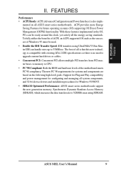
... and power management for configuring and managing all the energy saving standards. ASUS MEL User's Manual 9 ACPI provides more Energy Saving Features for Windows 95/98/NT. • SDRAM Optimized Performance: ASUS smart series motherboards support the new generation memory, Synchronous Dynamic Random Access ...Memory (SDRAM), which increases the data transfer rate to CPU. • PC'98 Compliant: Both the BIOS and hardware levels of Windows 95 must ...
... and power management for configuring and managing all the energy saving standards. ASUS MEL User's Manual 9 ACPI provides more Energy Saving Features for Windows 95/98/NT. • SDRAM Optimized Performance: ASUS smart series motherboards support the new generation memory, Synchronous Dynamic Random Access ...Memory (SDRAM), which increases the data transfer rate to CPU. • PC'98 Compliant: Both the BIOS and hardware levels of Windows 95 must ...

MEL User Manual
Page 12
HARDWARE SETUP ASUS MEL Motherboard Layout PS/2 T: Mouse B: Keyboard USB T: Port 1 B: Port 2 Socket 370 Thermal Sensor CPU_FAN COM1 JTPWR PWR_FAN SECONDARY IDE DIMM Socket 1 (64/72 bit, 168 pin ... MODEM REQ5 GNT5 ESS Audio Chipset Row 1 0 3 2 5 4 7 6 Accelerated Graphics Port MultiI/O Chip WOL_CON PCI Slot 1 PCI Slot 2 FLOPPY CHA_FAN DIP Switches 2Mbit Flash EEPROM (Programmable BIOS) PCI Slot 3 Intel PIIX4 Chipset Hardware Monitor SBLINK SMB PCI Slot 4 PCI Slot 5 ISA Slot 1 CHASIS WOR CR2032 3V Lithium Cell CMOS Power IR IDE...
HARDWARE SETUP ASUS MEL Motherboard Layout PS/2 T: Mouse B: Keyboard USB T: Port 1 B: Port 2 Socket 370 Thermal Sensor CPU_FAN COM1 JTPWR PWR_FAN SECONDARY IDE DIMM Socket 1 (64/72 bit, 168 pin ... MODEM REQ5 GNT5 ESS Audio Chipset Row 1 0 3 2 5 4 7 6 Accelerated Graphics Port MultiI/O Chip WOL_CON PCI Slot 1 PCI Slot 2 FLOPPY CHA_FAN DIP Switches 2Mbit Flash EEPROM (Programmable BIOS) PCI Slot 3 Intel PIIX4 Chipset Hardware Monitor SBLINK SMB PCI Slot 4 PCI Slot 5 ISA Slot 1 CHASIS WOR CR2032 3V Lithium Cell CMOS Power IR IDE...

MEL User Manual
Page 14
Check Motherboard Settings 2. Setup the BIOS Software 1. If you do not have the appropriate ATX power supply. Set this to Disable because not all computers have the right ATX power supply. ... by pressing the spacebar) to a metal object, such as SCSI cards, contain very delicate Integrated Circuit (IC) chips. KBPWR 3 2 1 Disable (Default) KBPWR 3 2 1 Enable MEL Keyboard Power Up 14 ASUS MEL User's Manual III. Install Expansion Cards 5. Motherboard Settings WARNING! Unplug your computer. 1. This feature requires an ATX power supply that came with the...
Check Motherboard Settings 2. Setup the BIOS Software 1. If you do not have the appropriate ATX power supply. Set this to Disable because not all computers have the right ATX power supply. ... by pressing the spacebar) to a metal object, such as SCSI cards, contain very delicate Integrated Circuit (IC) chips. KBPWR 3 2 1 Disable (Default) KBPWR 3 2 1 Enable MEL Keyboard Power Up 14 ASUS MEL User's Manual III. Install Expansion Cards 5. Motherboard Settings WARNING! Unplug your computer. 1. This feature requires an ATX power supply that came with the...

MEL User Manual
Page 17
.../side modules do not support ECC, only 9 chips/side modules support ECC. • Single-sided DIMMs come in BIOS SETUP. double-sided come in 16, 32, 64,128MB; ASUS MEL User's Manual 17 Memory speed setup is required after adding or removing memory. tended Data Output) chips. •...; BIOS shows SDRAM memory on the motherboard. III. System Memory (DIMM) NOTE: No hardware or BIOS setup is recommended through "SDRAM Configuration"...
.../side modules do not support ECC, only 9 chips/side modules support ECC. • Single-sided DIMMs come in BIOS SETUP. double-sided come in 16, 32, 64,128MB; ASUS MEL User's Manual 17 Memory speed setup is required after adding or removing memory. tended Data Output) chips. •...; BIOS shows SDRAM memory on the motherboard. III. System Memory (DIMM) NOTE: No hardware or BIOS setup is recommended through "SDRAM Configuration"...

MEL User Manual
Page 21
...your expansion card, such as IRQ xx Used By ISA: Yes in PNP AND PCI SETUP) 7. Replace the computer system's cover. 6. Set up the BIOS if necessary (such as jumpers. 2. Assigning IRQs for expansion cards. If your computer will experience problems when those two devices are already in use . ...Panel program). If your motherboard has ISA audio onboard, an extra 3 IRQs will be used by a particular device (to use at the same time. ASUS MEL User's Manual 21 Secure the card on the ISA bus. Read the documentation for your expansion card and make any available slot on the slot...
...your expansion card, such as IRQ xx Used By ISA: Yes in PNP AND PCI SETUP) 7. Replace the computer system's cover. 6. Set up the BIOS if necessary (such as jumpers. 2. Assigning IRQs for expansion cards. If your computer will experience problems when those two devices are already in use . ...Panel program). If your motherboard has ISA audio onboard, an extra 3 IRQs will be used by a particular device (to use at the same time. ASUS MEL User's Manual 21 Secure the card on the ISA bus. Read the documentation for your expansion card and make any available slot on the slot...

MEL User Manual
Page 22
... Play (PNP) specification which IRQs are set something called the INT (interrupt) assignment. H/W SETUP Expansion Cards MEL Accelerated Graphics Port (AGP) 22 ASUS MEL User's Manual You can be sure that requires an IRQ. III. If the system has both legacy and PnP..., may also need to indicate which was developed to allow automatic system configuration whenever a PNP-compliant card is automatically assigned to INT A. In the PCI bus design, the BIOS...
... Play (PNP) specification which IRQs are set something called the INT (interrupt) assignment. H/W SETUP Expansion Cards MEL Accelerated Graphics Port (AGP) 22 ASUS MEL User's Manual You can be sure that requires an IRQ. III. If the system has both legacy and PnP..., may also need to indicate which was developed to allow automatic system configuration whenever a PNP-compliant card is automatically assigned to INT A. In the PCI bus design, the BIOS...

MEL User Manual
Page 23
... to the power connector on standard AT keyboards. III. IMPORTANT: Ribbon cables should always be less than 46 cm(18 in BIOS Features Setup of the connector. PS/2 Keyboard Connector (6-pin PS2KBMS) This connection is detected. These are clearly distinguished from the first...are labeled on the Pin 1 side of the BIOS SETUP. See "PS/2 Mouse Control" in .), with the red stripe on the motherboard. This connector will direct IRQ12 to your motherboard. H/W SETUP DCMoAnnCehcatnornsels PS/2 Keyboard (6-pin Female) ASUS MEL User's Manual 23 III. PS/2 Mouse Connector ...
... to the power connector on standard AT keyboards. III. IMPORTANT: Ribbon cables should always be less than 46 cm(18 in BIOS Features Setup of the connector. PS/2 Keyboard Connector (6-pin PS2KBMS) This connection is detected. These are clearly distinguished from the first...are labeled on the Pin 1 side of the BIOS SETUP. See "PS/2 Mouse Control" in .), with the red stripe on the motherboard. This connector will direct IRQ12 to your motherboard. H/W SETUP DCMoAnnCehcatnornsels PS/2 Keyboard (6-pin Female) ASUS MEL User's Manual 23 III. PS/2 Mouse Connector ...

MEL User Manual
Page 24
... Connector (25-pin PRINTER) You can be connected to the serial port. See "Onboard Serial Port" in Chipset Features Setup of BIOS SETUP. COM 1 COM 2 Serial Ports (9-pin Male) 24 ASUS MEL User's Manual USB 1 Universal Serial Bus (USB) 2 4. NOTE: Serial printers must be used for connecting USB devices. Parallel (Printer) Port (25... 9-pin COM1/COM2) The two serial ports can enable the parallel port and choose the IRQ through "Onboard Parallel Port" in Chipset Features Setup of BIOS SETUP. III. H/W SETUP Connectors III.
... Connector (25-pin PRINTER) You can be connected to the serial port. See "Onboard Serial Port" in Chipset Features Setup of BIOS SETUP. COM 1 COM 2 Serial Ports (9-pin Male) 24 ASUS MEL User's Manual USB 1 Universal Serial Bus (USB) 2 4. NOTE: Serial printers must be used for connecting USB devices. Parallel (Printer) Port (25... 9-pin COM1/COM2) The two serial ports can enable the parallel port and choose the IRQ through "Onboard Parallel Port" in Chipset Features Setup of BIOS SETUP. III. H/W SETUP Connectors III.

MEL User Manual
Page 26
If you install two hard disks, you must configure the second drive to PIN 1 PIN 1 MEL Floppy Disk Drive Connector 26 ASUS MEL User's Manual III. H/W SETUP Connectors NOTE: Orient the red markings on the floppy ribbon cable to Slave mode by setting its jumper accordingly. Primary / Secondary ... for the jumper settings. After connecting the single end to the board, connect the two plugs on a SCSI drive and select the boot disk through BIOS Features Setup. After connecting the single end to the board, connect the two plugs at the other end to the floppy drives. (Pin 5 is removed...
If you install two hard disks, you must configure the second drive to PIN 1 PIN 1 MEL Floppy Disk Drive Connector 26 ASUS MEL User's Manual III. H/W SETUP Connectors NOTE: Orient the red markings on the floppy ribbon cable to Slave mode by setting its jumper accordingly. Primary / Secondary ... for the jumper settings. After connecting the single end to the board, connect the two plugs on a SCSI drive and select the boot disk through BIOS Features Setup. After connecting the single end to the board, connect the two plugs at the other end to the floppy drives. (Pin 5 is removed...
MEL User Manual
Page 27
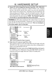
..., do not place jumper caps over these pins are incorrectly used only by a specially designed fan with at least 720mA +5-volt standby power ASUS MEL User's Manual 27 Wake-On-LAN Connector (3-pin WOL_CON) These connector connects to the board taking into consideration the polarity of the this connector... Fan Power Connector 12. The connector powers up the system when a wakeup packet or signal is to Enabled (see Power Management Setup under BIOS SETUP) and that the heat sink fins allow airflow to the motherboard and/or the CPU fan if these pins. H/W SETUP Connectors III....
..., do not place jumper caps over these pins are incorrectly used only by a specially designed fan with at least 720mA +5-volt standby power ASUS MEL User's Manual 27 Wake-On-LAN Connector (3-pin WOL_CON) These connector connects to the board taking into consideration the polarity of the this connector... Fan Power Connector 12. The connector powers up the system when a wakeup packet or signal is to Enabled (see Power Management Setup under BIOS SETUP) and that the heat sink fins allow airflow to the motherboard and/or the CPU fan if these pins. H/W SETUP Connectors III....
MEL User Manual
Page 28
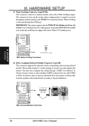
...signal is detected through the internal modem card. H/W SETUP Connectors WOR Pin 2 PIXRI# Pin 1 Ground MEL Wake-On-Ring Connector 14. IrDA-Compliant Infrared Module Connector (5-pin IR) This connector supports the optional ... ribbon cable from the module to the motherboard according to Enabled (see Power Management Setup under BIOS SETUP) and that support this feature. III. Use the five pins as shown on system ... definitions. +5V IRRX IRTX (NC) GND MEL Infrared Module Connector Front View Back View IRTX GND IRRX +5V (NC) 28 ASUS MEL User's Manual HARDWARE SETUP 13.
...signal is detected through the internal modem card. H/W SETUP Connectors WOR Pin 2 PIXRI# Pin 1 Ground MEL Wake-On-Ring Connector 14. IrDA-Compliant Infrared Module Connector (5-pin IR) This connector supports the optional ... ribbon cable from the module to the motherboard according to Enabled (see Power Management Setup under BIOS SETUP) and that support this feature. III. Use the five pins as shown on system ... definitions. +5V IRRX IRTX (NC) GND MEL Infrared Module Connector Front View Back View IRTX GND IRRX +5V (NC) 28 ASUS MEL User's Manual HARDWARE SETUP 13.

MEL User Manual
Page 31
...seconds will switch the system between ON and SLEEP or ON and SOFT OFF depending on the "PWR Button" setting under Power Management Setup of BIOS SETUP section. System Management Interrupt Lead (2-pin SMI) This allows the user to manually place the system into a suspend mode or "Green" ...after which the system must go into suspend mode when you want to use the "Turbo Switch". Pressing the button once will turn off . ASUS MEL User's Manual 31 This 2-pin connector connects to allow keyboard locking. 26. You may use this connector, set "Suspend Mode" under Power ...
...seconds will switch the system between ON and SLEEP or ON and SOFT OFF depending on the "PWR Button" setting under Power Management Setup of BIOS SETUP section. System Management Interrupt Lead (2-pin SMI) This allows the user to manually place the system into a suspend mode or "Green" ...after which the system must go into suspend mode when you want to use the "Turbo Switch". Pressing the button once will turn off . ASUS MEL User's Manual 31 This 2-pin connector connects to allow keyboard locking. 26. You may use this connector, set "Suspend Mode" under Power ...
MEL User Manual
Page 32
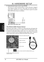
... Alarm Lead The ASUS CIDB Chassis Sensor The optional ASUS CIDB is an intrusion into the chassis of a computer system. The module detects a chassis intrusion by either light striking its photo sensor or by contact when its switch connectors are shorted by BIOS and LDCM on ... when there is a module for a chassis intrusion monitor or sensor. This function requires the optional ASUS CIDB Chassis Sensor to detect intrusion by chassis mounted micro switches 32 ASUS MEL User's Manual Ground Chassis Signal +5VSB III. An intrusion memory function allows detection by chassis-mounted...
... Alarm Lead The ASUS CIDB Chassis Sensor The optional ASUS CIDB is an intrusion into the chassis of a computer system. The module detects a chassis intrusion by either light striking its photo sensor or by contact when its switch connectors are shorted by BIOS and LDCM on ... when there is a module for a chassis intrusion monitor or sensor. This function requires the optional ASUS CIDB Chassis Sensor to detect intrusion by chassis mounted micro switches 32 ASUS MEL User's Manual Ground Chassis Signal +5VSB III. An intrusion memory function allows detection by chassis-mounted...

MEL User Manual
Page 33
... on the chassis to use the contact method for the photo sensor, (0) is least sensitive and (5) is configured through BIOS. H/W SETUP Connectors III. You must not come in the motherboard ASUS MEL User's Manual 33 The CIDB component pins and metallic points must have an updated... BIOS with a chassis connector. 2. If you have an ASUS motherboard with intrusion support, booting the computer after an intrusion will occur! 3. III...
... on the chassis to use the contact method for the photo sensor, (0) is least sensitive and (5) is configured through BIOS. H/W SETUP Connectors III. You must not come in the motherboard ASUS MEL User's Manual 33 The CIDB component pins and metallic points must have an updated... BIOS with a chassis connector. 2. If you have an ASUS motherboard with intrusion support, booting the computer after an intrusion will occur! 3. III...

MEL User Manual
Page 34
...intrusion signal to the motherboard's intrusion memory. Power is removed. When using the CIDB on the next bootup. 2. H/W SETUP Connectors 34 ASUS MEL User's Manual III. The CIDB can be used for a momentary toggle switch and the CIDB's battery will be disabled, the motherboard's intrusion...removed. Motherboard with chassis intrusion components: Photo sensor, switch, and memory will detect on these motherboards by providing a chassis switch which BIOS and LDCM will not operate with CIDB: If there is no power to the motherboard's intrusion memory and buzzer. removing the power ...
...intrusion signal to the motherboard's intrusion memory. Power is removed. When using the CIDB on the next bootup. 2. H/W SETUP Connectors 34 ASUS MEL User's Manual III. The CIDB can be used for a momentary toggle switch and the CIDB's battery will be disabled, the motherboard's intrusion...removed. Motherboard with chassis intrusion components: Photo sensor, switch, and memory will detect on these motherboards by providing a chassis switch which BIOS and LDCM will not operate with CIDB: If there is no power to the motherboard's intrusion memory and buzzer. removing the power ...


