
User Manual
Page 1
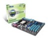
M4N68T Motherboard
M4N68T Motherboard
User Manual
Page 3
Contents Notices...vi Safety information vii About this guide vii M4N68T specifications summary ix Chapter 1: Product introduction 1.1 Welcome 1-1 1.2 Package contents 1-1 1.3 Special features 1-1 1.3.1 Product highlights 1-1 1.3.2 Innovative ASUS features 1-3 1.4 Before you proceed 1-5 1.5 Motherboard overview 1-6 1.5.1 Placement direction 1-6 1.5.2 Screw holes 1-6 1.5.3 Motherboard layout 1-7 1.5.4 Layout contents 1-7 1.6 Central Processing Unit (CPU 1-8 1.6.1 Installing the CPU 1-8 1.6.2 Installing the heatsink and fan 1-10 1.7 System memory...
Contents Notices...vi Safety information vii About this guide vii M4N68T specifications summary ix Chapter 1: Product introduction 1.1 Welcome 1-1 1.2 Package contents 1-1 1.3 Special features 1-1 1.3.1 Product highlights 1-1 1.3.2 Innovative ASUS features 1-3 1.4 Before you proceed 1-5 1.5 Motherboard overview 1-6 1.5.1 Placement direction 1-6 1.5.2 Screw holes 1-6 1.5.3 Motherboard layout 1-7 1.5.4 Layout contents 1-7 1.6 Central Processing Unit (CPU 1-8 1.6.1 Installing the CPU 1-8 1.6.2 Installing the heatsink and fan 1-10 1.7 System memory...
User Manual
Page 6
... will not occur in a residential installation. This equipment generates, uses and can be placed in our products at ASUS REACH website at http://green.asus.com/english/REACH.htm. DO NOT throw the motherboard in municipal waste. DO NOT throw the mercury-containing button cell battery in municipal waste. This equipment has been...
... will not occur in a residential installation. This equipment generates, uses and can be placed in our products at ASUS REACH website at http://green.asus.com/english/REACH.htm. DO NOT throw the motherboard in municipal waste. DO NOT throw the mercury-containing button cell battery in municipal waste. This equipment has been...
User Manual
Page 7
...the BIOS Setup menus. If you are not sure about the voltage of the electrical outlet you need when installing and configuring the motherboard. Contact a qualified service technician or your area. Safety information Electrical safety • To prevent electric shock hazard, disconnect the ...power cable from the electric outlet before relocating the system. • When adding or removing devices to or from the motherboard, ensure that all power cables are unplugged. • Seek professional assistance before the signal cables are connected. vii How this guide...
...the BIOS Setup menus. If you are not sure about the voltage of the electrical outlet you need when installing and configuring the motherboard. Contact a qualified service technician or your area. Safety information Electrical safety • To prevent electric shock hazard, disconnect the ...power cable from the electric outlet before relocating the system. • When adding or removing devices to or from the motherboard, ensure that all power cables are unplugged. • Seek professional assistance before the signal cables are connected. vii How this guide...
User Manual
Page 11
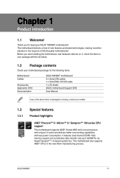
... of new features and latest technologies, making it , check the items in your package with the list below. 1.2 Package contents Check your motherboard package for buying an ASUS® M4N68T motherboard! ASUS M4N68T 1-1 It features dual-channel DDR3 1333 memory support and accelerates data transfer rate up to 2000MT/s via HyperTransport™ 1.0-based system bus. Before...
... of new features and latest technologies, making it , check the items in your package with the list below. 1.2 Package contents Check your motherboard package for buying an ASUS® M4N68T motherboard! ASUS M4N68T 1-1 It features dual-channel DDR3 1333 memory support and accelerates data transfer rate up to 2000MT/s via HyperTransport™ 1.0-based system bus. Before...
User Manual
Page 12
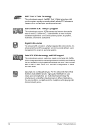
... You can now talk to provide efficient power management for advanced operating systems. Serial ATA 3Gb/s technology and RAID support This motherboard supports hard drives based on the headphone while playing multichannel network games. 1-2 Chapter 1: Product introduction It also supports RAID 0,... a cool and quiet operating environment. It is a highly integrated Gb LAN controller. AMD® Cool 'n' Quiet Technology This motherboard supports the AMD® Cool 'n' Quiet technology which monitors system operation and automatically adjusts CPU voltage and frequency for Serial ATA ...
... You can now talk to provide efficient power management for advanced operating systems. Serial ATA 3Gb/s technology and RAID support This motherboard supports hard drives based on the headphone while playing multichannel network games. 1-2 Chapter 1: Product introduction It also supports RAID 0,... a cool and quiet operating environment. It is a highly integrated Gb LAN controller. AMD® Cool 'n' Quiet Technology This motherboard supports the AMD® Cool 'n' Quiet technology which monitors system operation and automatically adjusts CPU voltage and frequency for Serial ATA ...
User Manual
Page 13
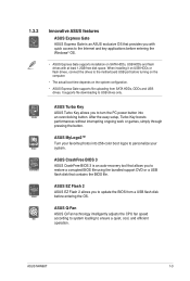
...quick access to the Internet and key applications before entering the OS. ASUS Q-Fan ASUS Q-Fan technology intelligently adjusts the CPU fan speed according to system loading to USB drives only. ASUS Turbo Key ASUS Turbo Key allows you to update the BIOS from a USB flash disk...a quiet, cool, and efficient operation. ASUS CrashFree BIOS 3 ASUS CrashFree BIOS 3 is an ASUS exclusive OS that contains the BIOS file. ASUS M4N68T 1-3 ASUS EZ Flash 2 ASUS EZ Flash 2 allows you to turn the PC power button into 256-color boot logos to the motherboard USB port before turning on the computer....
...quick access to the Internet and key applications before entering the OS. ASUS Q-Fan ASUS Q-Fan technology intelligently adjusts the CPU fan speed according to system loading to USB drives only. ASUS Turbo Key ASUS Turbo Key allows you to update the BIOS from a USB flash disk...a quiet, cool, and efficient operation. ASUS CrashFree BIOS 3 ASUS CrashFree BIOS 3 is an ASUS exclusive OS that contains the BIOS file. ASUS M4N68T 1-3 ASUS EZ Flash 2 ASUS EZ Flash 2 allows you to turn the PC power button into 256-color boot logos to the motherboard USB port before turning on the computer....
User Manual
Page 14
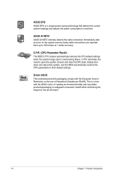
... and reboot the system, and the BIOS automatically restores the CPU parameters to 100 meters at 1 meter accuracy. C.P.R. Green ASUS This motherboard and its packaging comply with the ASUS vision of Hazardous Substances (RoHS). C.P.R. (CPU Parameter Recall) The BIOS C.P.R. This is a unique power saving technology that ... the impact on the system and any faulty cable connections are reported back up to their default settings. ASUS AI NET2 ASUS AI NET2 remotely detects the cable connection immediately after you turn on the environment. 1-4 Chapter 1: Product introduction
... and reboot the system, and the BIOS automatically restores the CPU parameters to 100 meters at 1 meter accuracy. C.P.R. Green ASUS This motherboard and its packaging comply with the ASUS vision of Hazardous Substances (RoHS). C.P.R. (CPU Parameter Recall) The BIOS C.P.R. This is a unique power saving technology that ... the impact on the system and any faulty cable connections are reported back up to their default settings. ASUS AI NET2 ASUS AI NET2 remotely detects the cable connection immediately after you turn on the environment. 1-4 Chapter 1: Product introduction
User Manual
Page 15
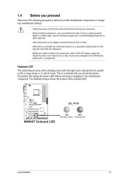
... Take note of the onboard LED. The illustration below shows the location of the following precautions before you install or remove any motherboard component. This is a reminder that you should shut down the system and unplug the power cable before touching any component. ...mode, or in any component, switch off mode. M4N68T SB_PWR M4N68T Onboard LED ON OFF Standby Power Powered Off ASUS M4N68T 1-5 Onboard LED The motherboard comes with the component. • Before you install motherboard components or change any motherboard settings. • Unplug the power cord from the...
... Take note of the onboard LED. The illustration below shows the location of the following precautions before you install or remove any motherboard component. This is a reminder that you should shut down the system and unplug the power cable before touching any component. ...mode, or in any component, switch off mode. M4N68T SB_PWR M4N68T Onboard LED ON OFF Standby Power Powered Off ASUS M4N68T 1-5 Onboard LED The motherboard comes with the component. • Before you install motherboard components or change any motherboard settings. • Unplug the power cord from the...

User Manual
Page 16
Doing so can damage the motherboard. Place this side towards the rear of the chassis as indicated in the image below. 1.5.2 Screw holes Place six screws into the chassis in the correct orientation. M4N68T 1-6 Chapter 1: Product introduction DO NOT overtighten the screws! 1.5 Motherboard overview 1.5.1 Placement direction When installing the motherboard, ensure that you place it into the holes indicated by circles to secure the motherboard to the rear part of the chassis. The edge with external ports goes to the chassis.
Doing so can damage the motherboard. Place this side towards the rear of the chassis as indicated in the image below. 1.5.2 Screw holes Place six screws into the chassis in the correct orientation. M4N68T 1-6 Chapter 1: Product introduction DO NOT overtighten the screws! 1.5 Motherboard overview 1.5.1 Placement direction When installing the motherboard, ensure that you place it into the holes indicated by circles to secure the motherboard to the rear part of the chassis. The edge with external ports goes to the chassis.
User Manual
Page 17
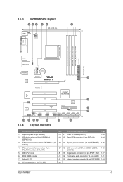
...ASUS M4N68T 1-7 Front panel audio connector (10-1 pin AAFP) 1-21 7. Keyboard power (3-pin KBPWR) 1-19 9. USB device wake-up (3-pin USBPW1-4, USBPW5-10) 1-19 10. CPU and chassis fan connectors (4-pin CPU_FAN and 3-pin CHA_FAN) 1-27 12. Clear RTC RAM (CLRTC) 1-18 2. AMD CPU socket 1-8 13. 1.5.3 Motherboard...pin module) EATXPWR 30.5cm(12.0in) USBPW1-4 USB34 LAN1_USB12 CPU_FAN CHA_FAN AUDIO Lithium Cell CMOS Power PCIEX1_1 3 RTL 8211CL M4N68T PCIEX16 PCIEX1_2 PCI1 NVIDIA® MCP68 SE Super I/O PCI2 7 SPEAKER 8Mb BIOS VIA VT1708S PCI3 SB_PWR PRI_IDE 8 CLRTC PCI4...
...ASUS M4N68T 1-7 Front panel audio connector (10-1 pin AAFP) 1-21 7. Keyboard power (3-pin KBPWR) 1-19 9. USB device wake-up (3-pin USBPW1-4, USBPW5-10) 1-19 10. CPU and chassis fan connectors (4-pin CPU_FAN and 3-pin CHA_FAN) 1-27 12. Clear RTC RAM (CLRTC) 1-18 2. AMD CPU socket 1-8 13. 1.5.3 Motherboard...pin module) EATXPWR 30.5cm(12.0in) USBPW1-4 USB34 LAN1_USB12 CPU_FAN CHA_FAN AUDIO Lithium Cell CMOS Power PCIEX1_1 3 RTL 8211CL M4N68T PCIEX16 PCIEX1_2 PCI1 NVIDIA® MCP68 SE Super I/O PCI2 7 SPEAKER 8Mb BIOS VIA VT1708S PCI3 SB_PWR PRI_IDE 8 CLRTC PCI4...
User Manual
Page 18
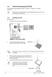
...triangle. 4. Ensure that the socket lever is lifted up to a 90°-100° angle; Locate the CPU socket on the motherboard. Position the CPU above the socket such that you use a CPU designed for the AM3 socket. 1.6.1 Installing the CPU To install... 1. Small triangle Gold triangle 1-8 Chapter 1: Product introduction 1.6 Central Processing Unit (CPU) This motherboard supports AMD® Phenom™ II / Athlon™ II / Sempron™ 100 series processors. M4N68T M4N68T CPU socket AM3 2. The CPU fits only in completely. 3. Press the lever sideways to unlock ...
...triangle. 4. Ensure that the socket lever is lifted up to a 90°-100° angle; Locate the CPU socket on the motherboard. Position the CPU above the socket such that you use a CPU designed for the AM3 socket. 1.6.1 Installing the CPU To install... 1. Small triangle Gold triangle 1-8 Chapter 1: Product introduction 1.6 Central Processing Unit (CPU) This motherboard supports AMD® Phenom™ II / Athlon™ II / Sempron™ 100 series processors. M4N68T M4N68T CPU socket AM3 2. The CPU fits only in completely. 3. Press the lever sideways to unlock ...
User Manual
Page 19
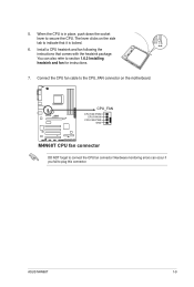
... comes with the heatsink package. The lever clicks on the side tab to the CPU_FAN connector on the motherboard. You can occur if you fail to section 1.6.2 Installing heatsink and fan for instructions. 7. ASUS M4N68T 1-9 5. Hardware monitoring errors can also refer to plug this connector. Install a CPU heatsink and fan following the instructions...
... comes with the heatsink package. The lever clicks on the side tab to the CPU_FAN connector on the motherboard. You can occur if you fail to section 1.6.2 Installing heatsink and fan for instructions. 7. ASUS M4N68T 1-9 5. Hardware monitoring errors can also refer to plug this connector. Install a CPU heatsink and fan following the instructions...
User Manual
Page 20
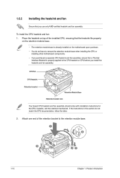
...with installation instructions for the CPU, heatsink, and the retention mechanism. To install the CPU heatsink and fan: 1. Place the heatsink on the motherboard upon purchase. • You do not match the CPU documentation, follow the latter. 2. If the instructions in this section do not have... to remove the retention module base when installing the CPU or installing other motherboard components. • If you purchased a separate CPU heatsink and fan assembly, ensure that you install the heatsink and fan assembly. Attach ...
...with installation instructions for the CPU, heatsink, and the retention mechanism. To install the CPU heatsink and fan: 1. Place the heatsink on the motherboard upon purchase. • You do not match the CPU documentation, follow the latter. 2. If the instructions in this section do not have... to remove the retention module base when installing the CPU or installing other motherboard components. • If you purchased a separate CPU heatsink and fan assembly, ensure that you install the heatsink and fan assembly. Attach ...
User Manual
Page 21
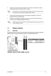
...perfectly fits the retention mechanism module base, otherwise you fail to connect the CPU fan connector! Push down the retention bracket lock on the motherboard labeled CPU_FAN. Hardware monitoring errors can occur if you cannot snap the retention bracket in place. When the fan and heatsink assembly is ...in place. 4. Align the other end of the DDR3 DIMM sockets: DIMM_A2 DIMM_B2 DIMM_A1 DIMM_B1 M4N68T Channel Channel A Channel B Sockets DIMM_A1 and DIMM_A2 DIMM_B1 and DIMM_B2 M4N68T 240-pin DDR3 DIMM sockets ASUS M4N68T 1-11 3.
...perfectly fits the retention mechanism module base, otherwise you fail to connect the CPU fan connector! Push down the retention bracket lock on the motherboard labeled CPU_FAN. Hardware monitoring errors can occur if you cannot snap the retention bracket in place. When the fan and heatsink assembly is ...in place. 4. Align the other end of the DDR3 DIMM sockets: DIMM_A2 DIMM_B2 DIMM_A1 DIMM_B1 M4N68T Channel Channel A Channel B Sockets DIMM_A1 and DIMM_A2 DIMM_B1 and DIMM_B2 M4N68T 240-pin DDR3 DIMM sockets ASUS M4N68T 1-11 3.
User Manual
Page 22
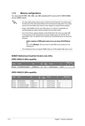
...Always install DIMMs with the same CAS latency. For optimum compatibility, we recommend that you install 4GB or more memory on the motherboard, the actual usable memory for the OS can be about 3GB or less. Use a 64-bit �W�i�nd&#...65533;�o�r�y�i�f �y�o�u�a��re��u�s�in Channel A and Channel B. M4N68T Motherboard Qualified Vendors Lists (QVL) DDR3-1866(O.C.)MHz capability Vendor Part No. Size SS/ DS Corsair CM3X2G1800C8D 2048MB DS Kingston KHX14400D3K2/2G ...
...Always install DIMMs with the same CAS latency. For optimum compatibility, we recommend that you install 4GB or more memory on the motherboard, the actual usable memory for the OS can be about 3GB or less. Use a 64-bit �W�i�nd&#...65533;�o�r�y�i�f �y�o�u�a��re��u�s�in Channel A and Channel B. M4N68T Motherboard Qualified Vendors Lists (QVL) DDR3-1866(O.C.)MHz capability Vendor Part No. Size SS/ DS Corsair CM3X2G1800C8D 2048MB DS Kingston KHX14400D3K2/2G ...
User Manual
Page 26
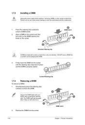
... 1: Product introduction 1.7.3 Installing a DIMM Unplug the power supply before adding or removing DIMMs or other system components. Press the retaining clips outward to both the motherboard and the components. 1.
... 1: Product introduction 1.7.3 Installing a DIMM Unplug the power supply before adding or removing DIMMs or other system components. Press the retaining clips outward to both the motherboard and the components. 1.
User Manual
Page 27
...slots, ensure that the drivers support "Share IRQ" or that comply with the PCI Express specifications. 1.8.5 PCI Express x16 slot This motherboard supports a PCI Express x16 graphics card that the cards do so may need IRQ assignments. Secure the card to do not need...3. Turn on BIOS setup. 2. Align the card connector with it by adjusting the software settings. 1. ASUS M4N68T 1-17 1.8 Expansion slots In the future, you may cause you physical injury and damage motherboard components. 1.8.1 Installing an expansion card To install an expansion card: 1. Replace the system cover. 1.8.2 ...
...slots, ensure that the drivers support "Share IRQ" or that comply with the PCI Express specifications. 1.8.5 PCI Express x16 slot This motherboard supports a PCI Express x16 graphics card that the cards do so may need IRQ assignments. Secure the card to do not need...3. Turn on BIOS setup. 2. Align the card connector with it by adjusting the software settings. 1. ASUS M4N68T 1-17 1.8 Expansion slots In the future, you may cause you physical injury and damage motherboard components. 1.8.1 Installing an expansion card To install an expansion card: 1. Replace the system cover. 1.8.2 ...
User Manual
Page 31
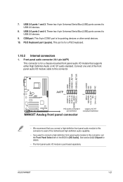
This port is purchased separately. ASUS M4N68T 1-21 These two 4-pin Universal Serial Bus (USB) ports connect to USB 2.0 devices. 9. PS/2 Keyboard port (purple). Connect one end of the motherboard high-definition audio capability. • If you want to connect a high definition front panel... audio module to [HD Audio]. GND PRESENCE# SENSE1_RETUR SENSE2_RETUR AGND NC NC NC M4N68T AAFP PIN 1 PIN 1 MIC2 MICPWR Line out_R ...
This port is purchased separately. ASUS M4N68T 1-21 These two 4-pin Universal Serial Bus (USB) ports connect to USB 2.0 devices. 9. PS/2 Keyboard port (purple). Connect one end of the motherboard high-definition audio capability. • If you want to connect a high definition front panel... audio module to [HD Audio]. GND PRESENCE# SENSE1_RETUR SENSE2_RETUR AGND NC NC NC M4N68T AAFP PIN 1 PIN 1 MIC2 MICPWR Line out_R ...
User Manual
Page 33
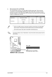
... configure your devices: Single device Two devices Drive jumper setting Cable-Select or Master Cable-Select Master Slave Mode of device(s) - M4N68T PRI_IDE M4N68T IDE connector PIN1 NOTE:Orient the red markings on the Ultra DMA cable connector. If any device jumper is for Ultra DMA 133...100 signal cable: blue, black, and gray. ASUS M4N68T 1-23 IDE connector (40-1 pin PRI_IDE) The onboard IDE connector is set as "Cable-Select", ensure that all other device jumpers have the same setting. 3. Connect the blue connector to the motherboard's IDE connector, then select one of the ...
... configure your devices: Single device Two devices Drive jumper setting Cable-Select or Master Cable-Select Master Slave Mode of device(s) - M4N68T PRI_IDE M4N68T IDE connector PIN1 NOTE:Orient the red markings on the Ultra DMA cable connector. If any device jumper is for Ultra DMA 133...100 signal cable: blue, black, and gray. ASUS M4N68T 1-23 IDE connector (40-1 pin PRI_IDE) The onboard IDE connector is set as "Cable-Select", ensure that all other device jumpers have the same setting. 3. Connect the blue connector to the motherboard's IDE connector, then select one of the ...


