User Manual
Page 7
...; Before installing the motherboard and adding devices on a stable surface. • If you add a device. • Before connecting or removing signal cables from connectors, slots, sockets and circuitry. • Avoid dust, humidity, and temperature extremes. vii If you are not sure about the voltage of the BIOS parameters are also provided...
...; Before installing the motherboard and adding devices on a stable surface. • If you add a device. • Before connecting or removing signal cables from connectors, slots, sockets and circuitry. • Avoid dust, humidity, and temperature extremes. vii If you are not sure about the voltage of the BIOS parameters are also provided...
User Manual
Page 9
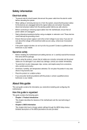
M4N68T specifications summary CPU Chipset Front side bus Memory Expansion slots Storage / RAID LAN Audio USB Back panel I/O ports AMD® Socket AM3 for AMD® Phenom™ II / Athlon™ II / Sempron™ 100 series processors AMD® Cool 'n' Quiet™ Technology AMD 64 ...architecture enables simultaneous 32-bit and 64-bit computing * Refer to www.asus.com for the AMD® CPU support ...
M4N68T specifications summary CPU Chipset Front side bus Memory Expansion slots Storage / RAID LAN Audio USB Back panel I/O ports AMD® Socket AM3 for AMD® Phenom™ II / Athlon™ II / Sempron™ 100 series processors AMD® Cool 'n' Quiet™ Technology AMD 64 ...architecture enables simultaneous 32-bit and 64-bit computing * Refer to www.asus.com for the AMD® CPU support ...
User Manual
Page 11
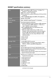
...features dual-channel DDR3 1333 memory support and accelerates data transfer rate up to 2000MT/s via HyperTransport™ 1.0-based system bus. ASUS M4N68T 1-1 The motherboard delivers a host of new features and latest technologies, making it , check the items in your package with ...highlights AMD® Phenom™ II / Athlon™ II / Sempron™ 100 series CPU support This motherboard supports AMD® Socket AM3 multi-core processors with unique L3 cache and delivers better overclocking capabilities with less power consumption. This motherboard also supports AMD® ...
...features dual-channel DDR3 1333 memory support and accelerates data transfer rate up to 2000MT/s via HyperTransport™ 1.0-based system bus. ASUS M4N68T 1-1 The motherboard delivers a host of new features and latest technologies, making it , check the items in your package with ...highlights AMD® Phenom™ II / Athlon™ II / Sempron™ 100 series CPU support This motherboard supports AMD® Socket AM3 multi-core processors with unique L3 cache and delivers better overclocking capabilities with less power consumption. This motherboard also supports AMD® ...
User Manual
Page 15
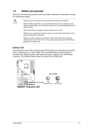
.... • Unplug the power cord from the wall socket before removing or plugging in soft-off the ATX power supply and detach its power cord. 1.4 Before you proceed Take note of the onboard LED. M4N68T SB_PWR M4N68T Onboard LED ON OFF Standby Power Powered Off ASUS M4N68T 1-5 This is ON, in sleep mode, or in...
.... • Unplug the power cord from the wall socket before removing or plugging in soft-off the ATX power supply and detach its power cord. 1.4 Before you proceed Take note of the onboard LED. M4N68T SB_PWR M4N68T Onboard LED ON OFF Standby Power Powered Off ASUS M4N68T 1-5 This is ON, in sleep mode, or in...
User Manual
Page 17
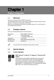
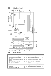
...1-18 2. ATX power connectors (24-pin EATXPWR, 4-pin 1-22 11. AMD CPU socket 1-8 13. Internal speaker connector (4- pin SPEAKER) 1-24 8. IDE connector (40-1 pin PRI_IDE) 1-23 ASUS M4N68T 1-7 DDR3 DIMM sockets 1-11 14. Serial ATA connectors (7-pin SATA1-4) 1-24 3. CPU and chassis fan connectors... module) EATXPWR 30.5cm(12.0in) USBPW1-4 USB34 LAN1_USB12 CPU_FAN CHA_FAN AUDIO Lithium Cell CMOS Power PCIEX1_1 3 RTL 8211CL M4N68T PCIEX16 PCIEX1_2 PCI1 NVIDIA® MCP68 SE Super I/O PCI2 7 SPEAKER 8Mb BIOS VIA VT1708S PCI3 SB_PWR PRI_IDE 8 CLRTC PCI4...
...1-18 2. ATX power connectors (24-pin EATXPWR, 4-pin 1-22 11. AMD CPU socket 1-8 13. Internal speaker connector (4- pin SPEAKER) 1-24 8. IDE connector (40-1 pin PRI_IDE) 1-23 ASUS M4N68T 1-7 DDR3 DIMM sockets 1-11 14. Serial ATA connectors (7-pin SATA1-4) 1-24 3. CPU and chassis fan connectors... module) EATXPWR 30.5cm(12.0in) USBPW1-4 USB34 LAN1_USB12 CPU_FAN CHA_FAN AUDIO Lithium Cell CMOS Power PCIEX1_1 3 RTL 8211CL M4N68T PCIEX16 PCIEX1_2 PCI1 NVIDIA® MCP68 SE Super I/O PCI2 7 SPEAKER 8Mb BIOS VIA VT1708S PCI3 SB_PWR PRI_IDE 8 CLRTC PCI4...
User Manual
Page 18
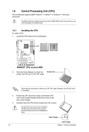
... in place. Small triangle Gold triangle 1-8 Chapter 1: Product introduction Carefully insert the CPU into the socket to a 90°-100° angle. M4N68T M4N68T CPU socket AM3 2. Position the CPU above the socket such that you use a CPU designed for the AM3 socket. 1.6.1 Installing the CPU To install a CPU: 1. DO NOT force the CPU into the...
... in place. Small triangle Gold triangle 1-8 Chapter 1: Product introduction Carefully insert the CPU into the socket to a 90°-100° angle. M4N68T M4N68T CPU socket AM3 2. Position the CPU above the socket such that you use a CPU designed for the AM3 socket. 1.6.1 Installing the CPU To install a CPU: 1. DO NOT force the CPU into the...
User Manual
Page 19
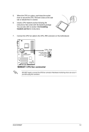
...DO NOT forget to section 1.6.2 Installing heatsink and fan for instructions. 7. Hardware monitoring errors can also refer to connect the CPU fan connector! ASUS M4N68T 1-9 The lever clicks on the side tab to the CPU_FAN connector on the motherboard. Install a CPU heatsink and fan following the instructions that it... is in place, push down the socket lever to plug this connector. When the CPU is locked. 6. Connect the CPU fan cable to indicate that comes with the heatsink package....
...DO NOT forget to section 1.6.2 Installing heatsink and fan for instructions. 7. Hardware monitoring errors can also refer to connect the CPU fan connector! ASUS M4N68T 1-9 The lever clicks on the side tab to the CPU_FAN connector on the motherboard. Install a CPU heatsink and fan following the instructions that it... is in place, push down the socket lever to plug this connector. When the CPU is locked. 6. Connect the CPU fan cable to indicate that comes with the heatsink package....
User Manual
Page 21
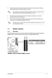
... plug this connector. 1.7 System memory 1.7.1 Overview The motherboard comes with four Double Data Rate 3 (DDR3) Dual Inline Memory Modules (DIMM) sockets. A clicking sound denotes that the fan and heatsink assembly perfectly fits the retention mechanism module base, otherwise you fail to the module base. ... CPU_FAN. When the fan and heatsink assembly is in place. 3. Align the other end of the DDR3 DIMM sockets: DIMM_A2 DIMM_B2 DIMM_A1 DIMM_B1 M4N68T Channel Channel A Channel B Sockets DIMM_A1 and DIMM_A2 DIMM_B1 and DIMM_B2 M4N68T 240-pin DDR3 DIMM sockets ASUS M4N68T 1-11
... plug this connector. 1.7 System memory 1.7.1 Overview The motherboard comes with four Double Data Rate 3 (DDR3) Dual Inline Memory Modules (DIMM) sockets. A clicking sound denotes that the fan and heatsink assembly perfectly fits the retention mechanism module base, otherwise you fail to the module base. ... CPU_FAN. When the fan and heatsink assembly is in place. 3. Align the other end of the DDR3 DIMM sockets: DIMM_A2 DIMM_B2 DIMM_A1 DIMM_B1 M4N68T Channel Channel A Channel B Sockets DIMM_A1 and DIMM_A2 DIMM_B1 and DIMM_B2 M4N68T 240-pin DDR3 DIMM sockets ASUS M4N68T 1-11
User Manual
Page 22
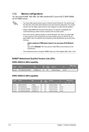
...introduction 1.7.2 Memory configurations You may install 512MB, 1GB, 2GB, and 4GB unbuffered ECC and non-ECC DDR3 DIMMs into the DIMM sockets. • You may install varying memory sizes in ��g�a��3�2�-�b�it�W��i&#...65533;r�y�i�f �y�o�u�a��re��u�s�in Channel A and Channel B. M4N68T Motherboard Qualified Vendors Lists (QVL) DDR3-1866(O.C.)MHz capability Vendor Part No. The system maps the total size of the lower...
...introduction 1.7.2 Memory configurations You may install 512MB, 1GB, 2GB, and 4GB unbuffered ECC and non-ECC DDR3 DIMMs into the DIMM sockets. • You may install varying memory sizes in ��g�a��3�2�-�b�it�W��i&#...65533;r�y�i�f �y�o�u�a��re��u�s�in Channel A and Channel B. M4N68T Motherboard Qualified Vendors Lists (QVL) DDR3-1866(O.C.)MHz capability Vendor Part No. The system maps the total size of the lower...
User Manual
Page 26
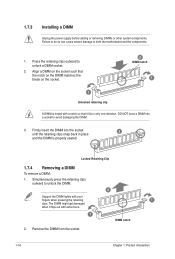
...seated. Simultaneously press the retaining clips outward to unlock a DIMM socket. 2. Locked Retaining Clip 1.7.4 Removing a DIMM To remove a DIMM: 1. Remove the DIMM from the socket. 1-16 Chapter 1: Product introduction Firmly insert the DIMM into a socket to both the motherboard and the components. 1. Failure to ...do so can cause severe damage to avoid damaging the DIMM. 3. DO NOT force a DIMM into the socket until the retaining clips snap back in only one direction. 1.7.3 Installing a DIMM Unplug the power supply before adding or removing DIMMs...
...seated. Simultaneously press the retaining clips outward to unlock a DIMM socket. 2. Locked Retaining Clip 1.7.4 Removing a DIMM To remove a DIMM: 1. Remove the DIMM from the socket. 1-16 Chapter 1: Product introduction Firmly insert the DIMM into a socket to both the motherboard and the components. 1. Failure to ...do so can cause severe damage to avoid damaging the DIMM. 3. DO NOT force a DIMM into the socket until the retaining clips snap back in only one direction. 1.7.3 Installing a DIMM Unplug the power supply before adding or removing DIMMs...


