
User Manual
Page 3
... About this guide...ix M4A79 Deluxe specifications summary xi Chapter 1: Product introduction 1.1 Welcome!...1-1 1.2 Package contents 1-1 1.3 Special features 1-2 1.3.1 Product highlights 1-2 1.3.2 ASUS unique features 1-3 1.3.3 ASUS intelligent performance and overclocking features........... 1-5 Chapter 2: Hardware information 2.1 Before you proceed 2-1 2.2 Motherboard overview 2-2 2.2.1 Motherboard layout 2-2 2.2.2 Layout contents...PCI Express 2.0 x16 slots 2-19 2.6 Jumpers...2-21 2.7 Onboard switches 2-23 2.8 Connectors 2-24 2.8.1 Rear panel connectors 2-24 iii
... About this guide...ix M4A79 Deluxe specifications summary xi Chapter 1: Product introduction 1.1 Welcome!...1-1 1.2 Package contents 1-1 1.3 Special features 1-2 1.3.1 Product highlights 1-2 1.3.2 ASUS unique features 1-3 1.3.3 ASUS intelligent performance and overclocking features........... 1-5 Chapter 2: Hardware information 2.1 Before you proceed 2-1 2.2 Motherboard overview 2-2 2.2.1 Motherboard layout 2-2 2.2.2 Layout contents...PCI Express 2.0 x16 slots 2-19 2.6 Jumpers...2-21 2.7 Onboard switches 2-23 2.8 Connectors 2-24 2.8.1 Rear panel connectors 2-24 iii
User Manual
Page 22
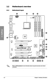
2.2 Motherboard overview 2.2.1 Motherboard layout Chapter 2 Refer to 2.8 Connectors for more information about rear panel connectors and internal connectors. 2-2 Chapter 2: Hardware information
2.2 Motherboard overview 2.2.1 Motherboard layout Chapter 2 Refer to 2.8 Connectors for more information about rear panel connectors and internal connectors. 2-2 Chapter 2: Hardware information
User Manual
Page 24
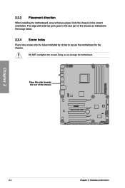
Doing so can damage the motherboard. Place this side towards the rear of the chassis as indicated in the correct orientation. The edge with external ports goes to the chassis. DO NOT overtighten the screws! 2.2.3 Placement direction When installing the motherboard, ensure that you place it into the chassis in the image below. 2.2.4 Screw holes Place nine screws into the holes indicated by circles to secure the motherboard to the rear part of the chassis Chapter 2 2-4 Chapter 2: Hardware information
Doing so can damage the motherboard. Place this side towards the rear of the chassis as indicated in the correct orientation. The edge with external ports goes to the chassis. DO NOT overtighten the screws! 2.2.3 Placement direction When installing the motherboard, ensure that you place it into the chassis in the image below. 2.2.4 Screw holes Place nine screws into the holes indicated by circles to secure the motherboard to the rear part of the chassis Chapter 2 2-4 Chapter 2: Hardware information
User Manual
Page 40
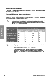
... Primary PCI Express x16 slots The primary PCI Express x16 slots support PCI Express x16 graphics cards that you plug the rear chassis fan cable to the motherboard connector labeled CHA_FAN1/2 for better thermal environment. Universal PCI Express x16 slots (max. Refer to the table below for ... two graphics card, install them to the blue slots. • If you install. Refer to x1 mode for details. x8 mode) This motherboard also supports universal PCI Express x16 slots with the PCI Express specifications. See page 2-33 for details. 2-20 Chapter 2: Hardware information The operating...
... Primary PCI Express x16 slots The primary PCI Express x16 slots support PCI Express x16 graphics cards that you plug the rear chassis fan cable to the motherboard connector labeled CHA_FAN1/2 for better thermal environment. Universal PCI Express x16 slots (max. Refer to the table below for ... two graphics card, install them to the blue slots. • If you install. Refer to x1 mode for details. x8 mode) This motherboard also supports universal PCI Express x16 slots with the PCI Express specifications. See page 2-33 for details. 2-20 Chapter 2: Hardware information The operating...
User Manual
Page 44
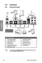
USB 2.0 ports 3 and 4 10. LAN (RJ-45) port** 5. USB 2.0 ports 5 and 6 7. Optical S/PDIF Out port 8. See section 3.4.2 Storage Configuration for details. 2-24 Chapter 2: Hardware information USB 2.0 ports 1 and 2 11. Coaxial S/PDIF Out port 3. PS/2 mouse port (green) 2. IEEE 1394a port 4. Audio I/O ports*** * To use hot-plug, set the OnChip SATA Type in the BIOS settings to [AHCI] mode. 2.8 Connectors 2.8.1 Rear panel connectors Chapter 2 Rear panel connectors 1. PS/2 keyboard port (purple) 6. External SATA port* 9.
USB 2.0 ports 3 and 4 10. LAN (RJ-45) port** 5. USB 2.0 ports 5 and 6 7. Optical S/PDIF Out port 8. See section 3.4.2 Storage Configuration for details. 2-24 Chapter 2: Hardware information USB 2.0 ports 1 and 2 11. Coaxial S/PDIF Out port 3. PS/2 mouse port (green) 2. IEEE 1394a port 4. Audio I/O ports*** * To use hot-plug, set the OnChip SATA Type in the BIOS settings to [AHCI] mode. 2.8 Connectors 2.8.1 Rear panel connectors Chapter 2 Rear panel connectors 1. PS/2 keyboard port (purple) 6. External SATA port* 9.
User Manual
Page 45
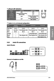
... - 6-channel 8-channel Line In Front Speaker Out Mic In Center/Subwoofer Rear Speaker Out - Chapter 2 ** LAN port LED indications Status OFF 10 Mbps connection 100 Mbps connection Left LED OFF Orange (blinking during data activity) OFF 1 Gbps ... Headset 2-channel Line In Line Out Mic In - - - 4-channel Line In Front Speaker Out Mic In - Line In Front Speaker Out Mic In Center/Subwoofer Rear Speaker Out Side Speaker Out 2.8.2 Audio I/O connections Audio I/O ports Connect to Headphone and Mic ASUS M4A79 Deluxe 2-25
... - 6-channel 8-channel Line In Front Speaker Out Mic In Center/Subwoofer Rear Speaker Out - Chapter 2 ** LAN port LED indications Status OFF 10 Mbps connection 100 Mbps connection Left LED OFF Orange (blinking during data activity) OFF 1 Gbps ... Headset 2-channel Line In Line Out Mic In - - - 4-channel Line In Front Speaker Out Mic In - Line In Front Speaker Out Mic In Center/Subwoofer Rear Speaker Out Side Speaker Out 2.8.2 Audio I/O connections Audio I/O ports Connect to Headphone and Mic ASUS M4A79 Deluxe 2-25
User Manual
Page 53
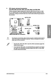
...Only the CPU_FAN, CHA_FAN 1 and CHA_FAN 2 connectors support the ASUS Q FAN 2 feature. • If you install two VGA cards, we recommend that you plug the rear chassis fan cable to the fan connectors on the motherboard, making sure that the black wire of each cable matches the... ground pin of 1 A~7 A (84 W max.) at +12V. Chapter 2 9. Connect the fan cables to the motherboard connector labled CHA_FAN1 or CHA_FAN2 for better themal environment. ASUS M4A79 Deluxe...
...Only the CPU_FAN, CHA_FAN 1 and CHA_FAN 2 connectors support the ASUS Q FAN 2 feature. • If you install two VGA cards, we recommend that you plug the rear chassis fan cable to the fan connectors on the motherboard, making sure that the black wire of each cable matches the... ground pin of 1 A~7 A (84 W max.) at +12V. Chapter 2 9. Connect the fan cables to the motherboard connector labled CHA_FAN1 or CHA_FAN2 for better themal environment. ASUS M4A79 Deluxe...