
User Manual
Page 1
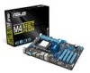
Motherboard M4A78LT PLUS
Motherboard M4A78LT PLUS

User Manual
Page 3
Contents Notices...vi Safety information vii About this guide viii M4A78LT PLUS specifications summary ix Chapter 1: Product introduction 1.1 Before you proceed 1-1 1.2 Motherboard overview 1-2 1.2.1 Placement direction 1-2 1.2.2 Screw holes 1-2 1.2.3 Motherboard layout 1-3 1.2.4 Layout contents 1-4 1.3 Central Processing Unit (CPU 1-4 1.3.1 Installing the CPU 1-4 1.3.2 Installing the heatsink and fan 1-6 1.4 System memory 1-7 1.4.1 Overview 1-7 1.4.2 Memory configurations 1-8 1.4.3 Installing a DIMM 1-11 1.4.4 Removing a DIMM 1-...
Contents Notices...vi Safety information vii About this guide viii M4A78LT PLUS specifications summary ix Chapter 1: Product introduction 1.1 Before you proceed 1-1 1.2 Motherboard overview 1-2 1.2.1 Placement direction 1-2 1.2.2 Screw holes 1-2 1.2.3 Motherboard layout 1-3 1.2.4 Layout contents 1-4 1.3 Central Processing Unit (CPU 1-4 1.3.1 Installing the CPU 1-4 1.3.2 Installing the heatsink and fan 1-6 1.4 System memory 1-7 1.4.1 Overview 1-7 1.4.2 Memory configurations 1-8 1.4.3 Installing a DIMM 1-11 1.4.4 Removing a DIMM 1-...
User Manual
Page 8
... this guide To ensure that you perform certain tasks properly, take note of the motherboard and the new technology it supports. • Chapter 2: BIOS information This chapter ...tells how to help you must press the Enter or Return key. Where to the ASUS contact information. 2. Typography Bold text Italics ++ Indicates a menu or an item to emphasize a...include optional documentation, such as warranty flyers, that you need when installing and configuring the motherboard. DANGER/WARNING: Information to prevent injury to yourself when trying to complete a task. ...
... this guide To ensure that you perform certain tasks properly, take note of the motherboard and the new technology it supports. • Chapter 2: BIOS information This chapter ...tells how to help you must press the Enter or Return key. Where to the ASUS contact information. 2. Typography Bold text Italics ++ Indicates a menu or an item to emphasize a...include optional documentation, such as warranty flyers, that you need when installing and configuring the motherboard. DANGER/WARNING: Information to prevent injury to yourself when trying to complete a task. ...
User Manual
Page 9
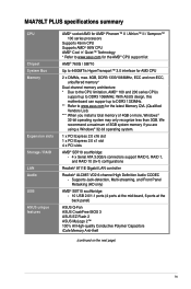
... total memory of 4GB or more, Windows® 32-bit operating system may only recognize less than 3GB. With ASUS design, this motherboard can support up to www.asus.com for the latest Memory QVL (Qualified Vendors List). *** When you are using a Windows® 32-bit ... at the mid-board, 6 ports at the back panel) ASUS Q-Fan ASUS CrashFree BIOS 3 ASUS EZ Flash 2 ASUS MyLogo 2™ 100% All High-quality Conductive Polymer Capacitors iCafe Memory Anti-theft (continued on the next page) ix M4A78LT PLUS specifications summary CPU Chipset System Bus Memory Expansion slots Storage / RAID...
... total memory of 4GB or more, Windows® 32-bit operating system may only recognize less than 3GB. With ASUS design, this motherboard can support up to www.asus.com for the latest Memory QVL (Qualified Vendors List). *** When you are using a Windows® 32-bit ... at the mid-board, 6 ports at the back panel) ASUS Q-Fan ASUS CrashFree BIOS 3 ASUS EZ Flash 2 ASUS MyLogo 2™ 100% All High-quality Conductive Polymer Capacitors iCafe Memory Anti-theft (continued on the next page) ix M4A78LT PLUS specifications summary CPU Chipset System Bus Memory Expansion slots Storage / RAID...

User Manual
Page 11
...detach its power cord. Chapter 1 Product introduction Thank you for the list of the following precautions before you install motherboard components or change any motherboard settings. • Unplug the power cord from the wall socket before touching any component. • Before handling ... the items is damaged or missing, contact your motherboard package. Before you start installing the motherboard, and hardware devices on a grounded antistatic pad or in your retailer. 1.1 Before you proceed Take note of accessories. ASUS M4A78LT PLUS 1-1 Failure to do so may cause severe damage...
...detach its power cord. Chapter 1 Product introduction Thank you for the list of the following precautions before you install motherboard components or change any motherboard settings. • Unplug the power cord from the wall socket before touching any component. • Before handling ... the items is damaged or missing, contact your motherboard package. Before you start installing the motherboard, and hardware devices on a grounded antistatic pad or in your retailer. 1.1 Before you proceed Take note of accessories. ASUS M4A78LT PLUS 1-1 Failure to do so may cause severe damage...

User Manual
Page 12
Doing so can damage the motherboard. Place this side towards the rear of the chassis as indicated in the image below. 1.2.2 Screw holes Place six screws into the chassis in the correct orientation. M4A78LT PLUS 1-2 Chapter 1: Product introduction The edge with external ports goes to the chassis. 1.2 Motherboard overview 1.2.1 Placement direction When installing the motherboard, ensure that you place it into the holes indicated by circles to secure the motherboard to the rear part of the chassis. DO NOT overtighten the screws!
Doing so can damage the motherboard. Place this side towards the rear of the chassis as indicated in the image below. 1.2.2 Screw holes Place six screws into the chassis in the correct orientation. M4A78LT PLUS 1-2 Chapter 1: Product introduction The edge with external ports goes to the chassis. 1.2 Motherboard overview 1.2.1 Placement direction When installing the motherboard, ensure that you place it into the holes indicated by circles to secure the motherboard to the rear part of the chassis. DO NOT overtighten the screws!
User Manual
Page 14
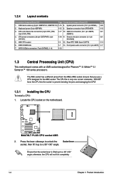
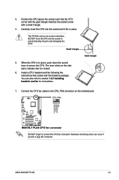
... prevent bending the pins and damaging the CPU! 1.3.1 Installing the CPU To install a CPU: 1. AM3 CPU socket 1-4 12. M4A78LT PLUS M4A78LT PLUS CPU socket AM3 2. SATA 3.0Gb/s connectors (7-pin SATA6G_1~4) 1-19 1.3 Central Processing Unit (CPU) This motherboard comes with an AM3 socket designed for the AM3 socket. DO NOT force the CPU into the socket...
... prevent bending the pins and damaging the CPU! 1.3.1 Installing the CPU To install a CPU: 1. AM3 CPU socket 1-4 12. M4A78LT PLUS M4A78LT PLUS CPU socket AM3 2. SATA 3.0Gb/s connectors (7-pin SATA6G_1~4) 1-19 1.3 Central Processing Unit (CPU) This motherboard comes with an AM3 socket designed for the AM3 socket. DO NOT force the CPU into the socket...
User Manual
Page 15
... and fan following the instructions that the CPU corner with the gold triangle matches the socket corner with the heatsink package. ASUS M4A78LT PLUS 1-5 The lever clicks on the motherboard. Connect the CPU fan cable to connect the CPU fan connector! 3. CPU_FAN CPU FAN PWM CPU FAN IN CPU FAN... PWR GND M4A78LT PLUS M4A78LT PLUS CPU fan connector DO NOT forget to the CPU_FAN connector on the side tab to prevent bending the pins ...
... and fan following the instructions that the CPU corner with the gold triangle matches the socket corner with the heatsink package. ASUS M4A78LT PLUS 1-5 The lever clicks on the motherboard. Connect the CPU fan cable to connect the CPU fan connector! 3. CPU_FAN CPU FAN PWM CPU FAN IN CPU FAN... PWR GND M4A78LT PLUS M4A78LT PLUS CPU fan connector DO NOT forget to the CPU_FAN connector on the side tab to prevent bending the pins ...

User Manual
Page 17
...M4A78LT PLUS Channel Channel A Channel B Sockets DIMM_A1 DIMM_B1 M4A78LT PLUS 240-pin DDR3 DIMM sockets ASUS M4A78LT PLUS 1-7 Hardware monitoring errors can occur if you cannot snap the retention bracket in place. DO NOT forget to the retention module base. Push down the retention bracket lock on the motherboard...on the retention mechanism to secure the heatsink and fan to plug this connector. 1.4 System memory 1.4.1 Overview This motherboard comes with less power consumption. A clicking sound denotes that the fan and heatsink assembly perfectly fits the retention mechanism ...
...M4A78LT PLUS Channel Channel A Channel B Sockets DIMM_A1 DIMM_B1 M4A78LT PLUS 240-pin DDR3 DIMM sockets ASUS M4A78LT PLUS 1-7 Hardware monitoring errors can occur if you cannot snap the retention bracket in place. DO NOT forget to the retention module base. Push down the retention bracket lock on the motherboard...on the retention mechanism to secure the heatsink and fan to plug this connector. 1.4 System memory 1.4.1 Overview This motherboard comes with less power consumption. A clicking sound denotes that the fan and heatsink assembly perfectly fits the retention mechanism ...
User Manual
Page 18
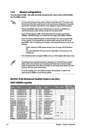
...CPUs support up to the memory address limitation on 32-bit Windows® OS, when you do any of the following: - M4A78LT PLUS Motherboard Qualified Vendors Lists (QVL) DDR3-1066MHz capability Vendors Part No. The system maps the total size of accessing information from the higher...-sized channel is then mapped for the dual-channel configuration. With ASUS design, this motherboard can be about 3GB or less. Size Crucial Crucial Crucial Crucial CT12864BA1067.8FF 1GB CT12872BA1067.9FF 1GB CT25664BA1067.16FF 2GB ...
...CPUs support up to the memory address limitation on 32-bit Windows® OS, when you do any of the following: - M4A78LT PLUS Motherboard Qualified Vendors Lists (QVL) DDR3-1066MHz capability Vendors Part No. The system maps the total size of accessing information from the higher...-sized channel is then mapped for the dual-channel configuration. With ASUS design, this motherboard can be about 3GB or less. Size Crucial Crucial Crucial Crucial CT12864BA1067.8FF 1GB CT12872BA1067.9FF 1GB CT25664BA1067.16FF 2GB ...

User Manual
Page 21
This special design prevents easy pilfering of the DIMM slots keep your memory modules. ASUS M4A78LT PLUS 1-11 DO NOT force a DIMM into the socket until the retaining clips snap back in place. Failure to do so can cause severe damage to ... A DIMM is properly seated. Install the two bundled iCafe Memory Anti-theft locks to unlock a DIMM socket. 2. Press the retaining clips outward to both the motherboard and the components. 1. Locked Retaining Clip 4. Firmly insert the DIMM into a socket in only one direction.
This special design prevents easy pilfering of the DIMM slots keep your memory modules. ASUS M4A78LT PLUS 1-11 DO NOT force a DIMM into the socket until the retaining clips snap back in place. Failure to do so can cause severe damage to ... A DIMM is properly seated. Install the two bundled iCafe Memory Anti-theft locks to unlock a DIMM socket. 2. Press the retaining clips outward to both the motherboard and the components. 1. Locked Retaining Clip 4. Firmly insert the DIMM into a socket in only one direction.
User Manual
Page 23
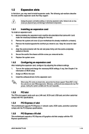
Remove the bracket opposite the slot that you may cause you removed earlier. 6. Assign an IRQ to the card. 3. ASUS M4A78LT PLUS 1-13 Unplug the power cord before adding or removing expansion cards. Secure the card to the chassis with the PCI Express specifications. Replace the ...slot support cards such as a LAN card, SCSI card, USB card, and other cards that comply with PCI specifications. 1.5.4 PCI Express x1 slot This motherboard supports PCI Express x1 network cards, SCSI cards, and other cards that comply with the PCI Express specifications. 1.5.5 PCI Express x16 slot This...
Remove the bracket opposite the slot that you may cause you removed earlier. 6. Assign an IRQ to the card. 3. ASUS M4A78LT PLUS 1-13 Unplug the power cord before adding or removing expansion cards. Secure the card to the chassis with the PCI Express specifications. Replace the ...slot support cards such as a LAN card, SCSI card, USB card, and other cards that comply with PCI specifications. 1.5.4 PCI Express x1 slot This motherboard supports PCI Express x1 network cards, SCSI cards, and other cards that comply with the PCI Express specifications. 1.5.5 PCI Express x16 slot This...
User Manual
Page 27
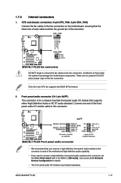
...the fan connectors. Only the 4-pin CPU fan supports the ASUS Q-Fan feature. 2. See section 2.4.3 Onboard Devices Configuration for a chassis-mounted front panel audio I/O module that you connect a high-definition front panel audio module to this connector to avail of the motherboard high-definition audio capability. • If you want to ... purchased separately. These are not jumpers! 1.7.2 Internal connectors 1. CPU and chassis connectors (4-pin CPU_FAN; 3-pin CHA_FAN) Connect the fan cables to the fan connectors. ASUS M4A78LT PLUS 1-17 Connect one end of the connector.
...the fan connectors. Only the 4-pin CPU fan supports the ASUS Q-Fan feature. 2. See section 2.4.3 Onboard Devices Configuration for a chassis-mounted front panel audio I/O module that you connect a high-definition front panel audio module to this connector to avail of the motherboard high-definition audio capability. • If you want to ... purchased separately. These are not jumpers! 1.7.2 Internal connectors 1. CPU and chassis connectors (4-pin CPU_FAN; 3-pin CHA_FAN) Connect the fan cables to the fan connectors. ASUS M4A78LT PLUS 1-17 Connect one end of the connector.

User Manual
Page 31
...+ GND NC USB+5V USB_P8USB_P8+ GND NC M4A78LT PLUS USB78 PIN 1 USB910 PIN 1 USB+5V USB_P9USB_P9+ GND USB+5V USB_P7USB_P7+ GND M4A78LT PLUS USB2.0 connectors Never connect a 1394 cable to use the chassis intrusion detection feature. +5VSB_MB Chassis Signal GND M4A78LT PLUS CHASSIS M4A78LT PLUS Chassis intrusion connector ASUS M4A78LT PLUS 1-21 By default, the pin labeled "Chassis...chassis intrusion sensor or switch cable to 480Mbps connection speed. These USB connectors comply with a jumper cap. Doing so will damage the motherboard! The signal is removed or replaced.
...+ GND NC USB+5V USB_P8USB_P8+ GND NC M4A78LT PLUS USB78 PIN 1 USB910 PIN 1 USB+5V USB_P9USB_P9+ GND USB+5V USB_P7USB_P7+ GND M4A78LT PLUS USB2.0 connectors Never connect a 1394 cable to use the chassis intrusion detection feature. +5VSB_MB Chassis Signal GND M4A78LT PLUS CHASSIS M4A78LT PLUS Chassis intrusion connector ASUS M4A78LT PLUS 1-21 By default, the pin labeled "Chassis...chassis intrusion sensor or switch cable to 480Mbps connection speed. These USB connectors comply with a jumper cap. Doing so will damage the motherboard! The signal is removed or replaced.
User Manual
Page 33
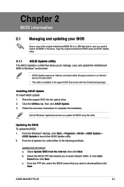
... through a network or an Internet Service Provider (ISP). • This utility is a utility that comes with the motherboard package. Copy the original motherboard BIOS using this utility. Select Update BIOS from the Internet a. From the FTP site, select the BIOS version that ..., or click Auto Select then click Next. c. Updating the BIOS To update the BIOS: 1. Select the ASUS FTP site nearest you to launch the ASUS Update utility. 2. b. ASUS M4A78LT PLUS 2-1 Place the support DVD into the optical drive. 2. Chapter 2 BIOS information 2.1 Managing and updating your...
... through a network or an Internet Service Provider (ISP). • This utility is a utility that comes with the motherboard package. Copy the original motherboard BIOS using this utility. Select Update BIOS from the Internet a. From the FTP site, select the BIOS version that ..., or click Auto Select then click Next. c. Updating the BIOS To update the BIOS: 1. Select the ASUS FTP site nearest you to launch the ASUS Update utility. 2. b. ASUS M4A78LT PLUS 2-1 Place the support DVD into the optical drive. 2. Chapter 2 BIOS information 2.1 Managing and updating your...
User Manual
Page 35
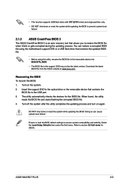
...file using the motherboard support DVD or a USB flash drive that contains the updated BIOS file. • Before using this utility, rename the BIOS file in the removable device into M4A78TPL.ROM. • The BIOS file in the support DVD may not be the latest version. ASUS M4A78LT PLUS 2-3 DO NOT... shut down or reset the system while updating the BIOS to prevent system boot failure! 2.1.3 ASUS CrashFree BIOS 3 The ASUS CrashFree BIOS 3 is an auto recovery tool that contains the BIOS file to ...
...file using the motherboard support DVD or a USB flash drive that contains the updated BIOS file. • Before using this utility, rename the BIOS file in the removable device into M4A78TPL.ROM. • The BIOS file in the support DVD may not be the latest version. ASUS M4A78LT PLUS 2-3 DO NOT... shut down or reset the system while updating the BIOS to prevent system boot failure! 2.1.3 ASUS CrashFree BIOS 3 The ASUS CrashFree BIOS 3 is an auto recovery tool that contains the BIOS file to ...

User Manual
Page 39
...: • Press ++ simultaneously. • Press the reset button on the system chassis. • Press the power button to guide you in this motherboard. ASUS M4A78LT PLUS 2-7 The BIOS screens include navigation keys and brief online help to turn the system off then back on your data or system. Do this... motherboard apply to most conditions to enter BIOS Setup using the BIOS Setup program. We recommend that you failed to ensure optimum performance. ...
...: • Press ++ simultaneously. • Press the reset button on the system chassis. • Press the power button to guide you in this motherboard. ASUS M4A78LT PLUS 2-7 The BIOS screens include navigation keys and brief online help to turn the system off then back on your data or system. Do this... motherboard apply to most conditions to enter BIOS Setup using the BIOS Setup program. We recommend that you failed to ensure optimum performance. ...

User Manual
Page 49
...options: [Power Off] [Power On] [Last State] Power on From S5 By RTC Alarm [Disabled] Enables or disables RTC to the motherboard, the field shows N/A. Configuration options: [Disabled] [Enabled] 2.5.5 HW Monitor Configuration CPU / MB Temperature [xxxºC/xxxºF] or ... monitor automatically detects and displays the motherboard and CPU temperatures. VCORE Voltage, 3.3V Voltage, 5V Voltage, 12V Voltage [xx.xxxV] or [Ignored] The onboard hardware monitor automatically detects the voltage output through the onboard voltage regulators. ASUS M4A78LT PLUS 2-17 2.5.3 ACPI APIC Support [...
...options: [Power Off] [Power On] [Last State] Power on From S5 By RTC Alarm [Disabled] Enables or disables RTC to the motherboard, the field shows N/A. Configuration options: [Disabled] [Enabled] 2.5.5 HW Monitor Configuration CPU / MB Temperature [xxxºC/xxxºF] or ... monitor automatically detects and displays the motherboard and CPU temperatures. VCORE Voltage, 3.3V Voltage, 5V Voltage, 12V Voltage [xx.xxxV] or [Ignored] The onboard hardware monitor automatically detects the voltage output through the onboard voltage regulators. ASUS M4A78LT PLUS 2-17 2.5.3 ACPI APIC Support [...
User Manual
Page 56
..., 2011 Year to begin affixing CE marking:2011 Signature Country: TAIWAN Authorized representative in Europe: ASUS COMPUTER GmbH Address, City: HARKORT STR. 21-23, 40880 RATINGEN Country: GERMANY declare the following apparatus: Product name : Motherboard Model name : M4A78LT PLUS conform with the essential requirements of the following specifications: FCC Part 15, Subpart B, Unintentional Radiators...
..., 2011 Year to begin affixing CE marking:2011 Signature Country: TAIWAN Authorized representative in Europe: ASUS COMPUTER GmbH Address, City: HARKORT STR. 21-23, 40880 RATINGEN Country: GERMANY declare the following apparatus: Product name : Motherboard Model name : M4A78LT PLUS conform with the essential requirements of the following specifications: FCC Part 15, Subpart B, Unintentional Radiators...


