
User Manual
Page 1
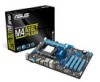
Motherboard M4A78LT PLUS
Motherboard M4A78LT PLUS

User Manual
Page 3
Contents Notices...vi Safety information vii About this guide viii M4A78LT PLUS specifications summary ix Chapter 1: Product introduction 1.1 Before you proceed 1-1 1.2 Motherboard overview 1-2 1.2.1 Placement direction 1-2 1.2.2 Screw holes 1-2 1.2.3 Motherboard layout 1-3 1.2.4 Layout contents 1-4 1.3 Central Processing Unit (CPU 1-4 1.3.1 Installing the ...
Contents Notices...vi Safety information vii About this guide viii M4A78LT PLUS specifications summary ix Chapter 1: Product introduction 1.1 Before you proceed 1-1 1.2 Motherboard overview 1-2 1.2.1 Placement direction 1-2 1.2.2 Screw holes 1-2 1.2.3 Motherboard layout 1-3 1.2.4 Layout contents 1-4 1.3 Central Processing Unit (CPU 1-4 1.3.1 Installing the ...
User Manual
Page 8
...1. Where to find more keys simultaneously, the key names are not part of the standard package. These documents are linked with a plus sign (+). Detailed descriptions of the BIOS parameters are also provided. Refer to emphasize a word or a phrase. Example: means that ...you need when installing and configuring the motherboard. Used to the ASUS contact information. 2. IMPORTANT: Instructions that you complete a task. About this guide is organized This guide contains the following parts: •...
...1. Where to find more keys simultaneously, the key names are not part of the standard package. These documents are linked with a plus sign (+). Detailed descriptions of the BIOS parameters are also provided. Refer to emphasize a word or a phrase. Example: means that ...you need when installing and configuring the motherboard. Used to the ASUS contact information. 2. IMPORTANT: Instructions that you complete a task. About this guide is organized This guide contains the following parts: •...
User Manual
Page 9
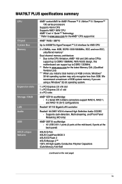
M4A78LT PLUS specifications summary CPU Chipset System Bus Memory Expansion slots Storage / RAID LAN Audio USB ASUS unique features AMD® socket AM3 for AMD® Phenom™ II / Athlon™ II / Sempron™ 100 series processors Supports 45nm CPU ...streaming, and Front Panel Retasking (HD only) AMD® SB710 southbridge: - 10 USB 2.0/1.1 ports (4 ports at the mid-board, 6 ports at the back panel) ASUS Q-Fan ASUS CrashFree BIOS 3 ASUS EZ Flash 2 ASUS MyLogo 2™ 100% All High-quality Conductive Polymer Capacitors iCafe Memory Anti-theft (continued on the next page) ix
M4A78LT PLUS specifications summary CPU Chipset System Bus Memory Expansion slots Storage / RAID LAN Audio USB ASUS unique features AMD® socket AM3 for AMD® Phenom™ II / Athlon™ II / Sempron™ 100 series processors Supports 45nm CPU ...streaming, and Front Panel Retasking (HD only) AMD® SB710 southbridge: - 10 USB 2.0/1.1 ports (4 ports at the mid-board, 6 ports at the back panel) ASUS Q-Fan ASUS CrashFree BIOS 3 ASUS EZ Flash 2 ASUS MyLogo 2™ 100% All High-quality Conductive Polymer Capacitors iCafe Memory Anti-theft (continued on the next page) ix

User Manual
Page 10
M4A78LT PLUS specifications summary Back panel I/O ports Internal connectors BIOS Manageability Accessories Support DVD Form factor 1 x PS/2 Mouse port (green) 1 x PS/2 Keyboard port (purple) 1 x COM port 1 x LAN (... connector 1 x Speaker connector 1 x 24-pin EATX power connector 1 x 4-pin ATX 12V power connector 8Mb Flash ROM, AMI BIOS, PnP, DMI 2.0, WfM 2.0, ACPI 2.0a, SM BIOS 2.6, ASUS EZ Flash 2, ASUS CrashFree BIOS 3 WfM 2.0, DMI 2.0, WOR by PME, PXE 2 x Serial ATA cables 1 x I/O shield 1 x User Manual 1 x Support DVD 2 x iCafe Memory Anti-theft locks Drivers...
M4A78LT PLUS specifications summary Back panel I/O ports Internal connectors BIOS Manageability Accessories Support DVD Form factor 1 x PS/2 Mouse port (green) 1 x PS/2 Keyboard port (purple) 1 x COM port 1 x LAN (... connector 1 x Speaker connector 1 x 24-pin EATX power connector 1 x 4-pin ATX 12V power connector 8Mb Flash ROM, AMI BIOS, PnP, DMI 2.0, WfM 2.0, ACPI 2.0a, SM BIOS 2.6, ASUS EZ Flash 2, ASUS CrashFree BIOS 3 WfM 2.0, DMI 2.0, WOR by PME, PXE 2 x Serial ATA cables 1 x I/O shield 1 x User Manual 1 x Support DVD 2 x iCafe Memory Anti-theft locks Drivers...

User Manual
Page 11
... list of the following precautions before touching any of the items is damaged or missing, contact your motherboard package. Refer to page x for buying an ASUS® M4A78LT PLUS motherboard! ASUS M4A78LT PLUS 1-1
... list of the following precautions before touching any of the items is damaged or missing, contact your motherboard package. Refer to page x for buying an ASUS® M4A78LT PLUS motherboard! ASUS M4A78LT PLUS 1-1

User Manual
Page 12
DO NOT overtighten the screws! Doing so can damage the motherboard. Place this side towards the rear of the chassis as indicated in the image below. 1.2.2 Screw holes Place six screws into the chassis in the correct orientation. 1.2 Motherboard overview 1.2.1 Placement direction When installing the motherboard, ensure that you place it into the holes indicated by circles to secure the motherboard to the rear part of the chassis. M4A78LT PLUS 1-2 Chapter 1: Product introduction The edge with external ports goes to the chassis.
DO NOT overtighten the screws! Doing so can damage the motherboard. Place this side towards the rear of the chassis as indicated in the image below. 1.2.2 Screw holes Place six screws into the chassis in the correct orientation. 1.2 Motherboard overview 1.2.1 Placement direction When installing the motherboard, ensure that you place it into the holes indicated by circles to secure the motherboard to the rear part of the chassis. M4A78LT PLUS 1-2 Chapter 1: Product introduction The edge with external ports goes to the chassis.
User Manual
Page 14
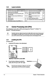
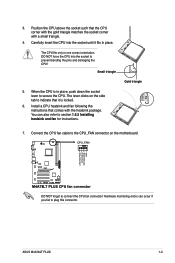
... correct orientation. Ensure that the socket lever is lifted up to prevent bending the pins and damaging the CPU! 1.3.1 Installing the CPU To install a CPU: 1. M4A78LT PLUS M4A78LT PLUS CPU socket AM3 2. 1.2.4 Layout contents Connectors/Jumpers/Slots/LED Page Connectors/Jumpers/Slots/LED Page 1. DDR3 DIMM slots 1-7 13. Keyboard power (3-pin KBPWR) 1-15...
... correct orientation. Ensure that the socket lever is lifted up to prevent bending the pins and damaging the CPU! 1.3.1 Installing the CPU To install a CPU: 1. M4A78LT PLUS M4A78LT PLUS CPU socket AM3 2. 1.2.4 Layout contents Connectors/Jumpers/Slots/LED Page Connectors/Jumpers/Slots/LED Page 1. DDR3 DIMM slots 1-7 13. Keyboard power (3-pin KBPWR) 1-15...
User Manual
Page 15
... the socket such that comes with a small triangle. 4. CPU_FAN CPU FAN PWM CPU FAN IN CPU FAN PWR GND M4A78LT PLUS M4A78LT PLUS CPU fan connector DO NOT forget to connect the CPU fan connector! ASUS M4A78LT PLUS 1-5 Gold triangle 7. Carefully insert the CPU into the socket to plug this connector. Install a CPU heatsink and fan following...
... the socket such that comes with a small triangle. 4. CPU_FAN CPU FAN PWM CPU FAN IN CPU FAN PWR GND M4A78LT PLUS M4A78LT PLUS CPU fan connector DO NOT forget to connect the CPU fan connector! ASUS M4A78LT PLUS 1-5 Gold triangle 7. Carefully insert the CPU into the socket to plug this connector. Install a CPU heatsink and fan following...

User Manual
Page 17
... better performance with two Double Data Rate 3 (DDR3) Dual Inline Memory Modules (DIMM) sockets. Align the other end of the DDR3 DIMM sockets: DIMM_A1 DIMM_B1 M4A78LT PLUS Channel Channel A Channel B Sockets DIMM_A1 DIMM_B1 M4A78LT PLUS 240-pin DDR3 DIMM sockets ASUS M4A78LT PLUS 1-7 3. DO NOT forget to the retention module base.
... better performance with two Double Data Rate 3 (DDR3) Dual Inline Memory Modules (DIMM) sockets. Align the other end of the DDR3 DIMM sockets: DIMM_A1 DIMM_B1 M4A78LT PLUS Channel Channel A Channel B Sockets DIMM_A1 DIMM_B1 M4A78LT PLUS 240-pin DDR3 DIMM sockets ASUS M4A78LT PLUS 1-7 3. DO NOT forget to the retention module base.
User Manual
Page 18
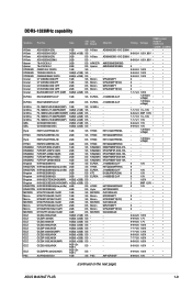
...more memory on the motherboard, the actual usable memory for overclocking may install varying memory sizes in Channel A and Channel B. M4A78LT PLUS Motherboard Qualified Vendors Lists (QVL) DDR3-1066MHz capability Vendors Part No. J1108BDBG-DJ-F(ECC) 7 D1288JPNDPLD9U 7 J1108BDSE-DJ-F 7... H5TQ2G83AFR 7 9GF22D9KPT 7 9HF22D9KPT(ECC) 7 9HF22D9KPT 7 9GF22D9KPT(ECC) 7 9BF27D9KPV 7-7-7-20 N2CB1G80CN-BE - - 7-7-7-20 - - With ASUS design, this motherboard can be about 3GB or less. Install a maximum of 3GB system memory if you want to support a full memory load...
...more memory on the motherboard, the actual usable memory for overclocking may install varying memory sizes in Channel A and Channel B. M4A78LT PLUS Motherboard Qualified Vendors Lists (QVL) DDR3-1066MHz capability Vendors Part No. J1108BDBG-DJ-F(ECC) 7 D1288JPNDPLD9U 7 J1108BDSE-DJ-F 7... H5TQ2G83AFR 7 9GF22D9KPT 7 9HF22D9KPT(ECC) 7 9HF22D9KPT 7 9GF22D9KPT(ECC) 7 9BF27D9KPV 7-7-7-20 N2CB1G80CN-BE - - 7-7-7-20 - - With ASUS design, this motherboard can be about 3GB or less. Install a maximum of 3GB system memory if you want to support a full memory load...
User Manual
Page 19
...; - 7-7-7-20 1.65V • • - 8-8-8-20 1.60V • • - 9-9-9-20 1.65V • A3P1GF3DGF 9-9-9-20 1.65V • • 8-8-8-24 1.5V • • (continued on the next page) ASUS M4A78LT PLUS 1-9 F3-10666CL7T-6GBPK(XMP) 6GB(3 x 2GB) DS - OCZ3G13334GK 4GB(2 x 2GB) DS - OCZ3X13334GK(XMP) 4GB(2 x 2GB) DS - OCZ3G1333LV8GK 8GB ( 2x 4GB ) DS - GV32GB1333C9DC 2GB(2 x 1GB) DS...
...; - 7-7-7-20 1.65V • • - 8-8-8-20 1.60V • • - 9-9-9-20 1.65V • A3P1GF3DGF 9-9-9-20 1.65V • • 8-8-8-24 1.5V • • (continued on the next page) ASUS M4A78LT PLUS 1-9 F3-10666CL7T-6GBPK(XMP) 6GB(3 x 2GB) DS - OCZ3G13334GK 4GB(2 x 2GB) DS - OCZ3X13334GK(XMP) 4GB(2 x 2GB) DS - OCZ3G1333LV8GK 8GB ( 2x 4GB ) DS - GV32GB1333C9DC 2GB(2 x 1GB) DS...

User Manual
Page 21
... only one direction. Locked Retaining Clip 4. iCafe Memory Anti-theft The two plastic locks at both ends of the DIMM slots keep your memory modules. ASUS M4A78LT PLUS 1-11 1.4.3 Installing a DIMM Unplug the power supply before adding or removing DIMMs or other system components. Align a DIMM on the socket such that it fits...
... only one direction. Locked Retaining Clip 4. iCafe Memory Anti-theft The two plastic locks at both ends of the DIMM slots keep your memory modules. ASUS M4A78LT PLUS 1-11 1.4.3 Installing a DIMM Unplug the power supply before adding or removing DIMMs or other system components. Align a DIMM on the socket such that it fits...
User Manual
Page 23
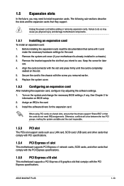
... the chassis with it by adjusting the software settings. 1. See Chapter 2 for the expansion card. Unplug the power cord before adding or removing expansion cards. ASUS M4A78LT PLUS 1-13 1.5 Expansion slots In the future, you intend to use . 4. Replace the system cover. 1.5.2 Configuring an expansion card After installing the expansion card, configure it...
... the chassis with it by adjusting the software settings. 1. See Chapter 2 for the expansion card. Unplug the power cord before adding or removing expansion cards. ASUS M4A78LT PLUS 1-13 1.5 Expansion slots In the future, you intend to use . 4. Replace the system cover. 1.5.2 Configuring an expansion card After installing the expansion card, configure it...
User Manual
Page 24
Plug the power cord and turn ON the computer. 4. M4A78LT PLUS CLRTC 12 23 Normal (Default) M4A78LT PLUS Clear RTC RAM Clear RTC To erase the RTC RAM: 1. You can automatically reset parameter settings to pins 1-2. 3. Move the jumper cap from pins 1-2 (default) ...
Plug the power cord and turn ON the computer. 4. M4A78LT PLUS CLRTC 12 23 Normal (Default) M4A78LT PLUS Clear RTC RAM Clear RTC To erase the RTC RAM: 1. You can automatically reset parameter settings to pins 1-2. 3. Move the jumper cap from pins 1-2 (default) ...
User Manual
Page 25
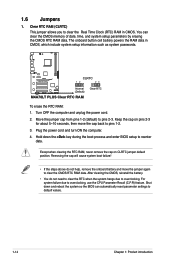
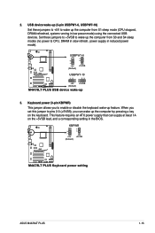
...). When you can supply at least 1A on the keyboard. KBPWR +5V +5VSB (Default) 12 23 M4A78LT PLUS M4A78LT PLUS Keyboard power setting ASUS M4A78LT PLUS 1-15 USBPW1-6 12 23 +5V +5VSB (Default) M4A78LT PLUS USBPW7-10 12 23 +5V +5VSB (Default) M4A78LT PLUS USB device wake-up feature. This feature requires an ATX power supply that can wake up the...
...). When you can supply at least 1A on the keyboard. KBPWR +5V +5VSB (Default) 12 23 M4A78LT PLUS M4A78LT PLUS Keyboard power setting ASUS M4A78LT PLUS 1-15 USBPW1-6 12 23 +5V +5VSB (Default) M4A78LT PLUS USBPW7-10 12 23 +5V +5VSB (Default) M4A78LT PLUS USB device wake-up feature. This feature requires an ATX power supply that can wake up the...
User Manual
Page 27
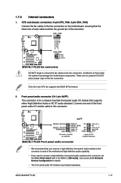
... NC PORT1 L PIN 1 AGND Line out_L NC Line out_R MICPWR MIC2 PIN 1 HD-audio-compliant pin definition Legacy AC'97 compliant definition M4A78LT PLUS Front panel audio connector • We recommend that supports either High Definition Audio or AC`97 audio standard. Front panel audio connector (10-1... CPU_FAN CPU FAN PWM CPU FAN IN CPU FAN PWR GND M4A78LT PLUS CHA_FAN GND +12V Rotation M4A78LT PLUS fan connectors DO NOT forget to connect the fan cables to the fan connectors on the fan connectors. ASUS M4A78LT PLUS 1-17 DO NOT place jumper caps on the motherboard, ensuring ...
... NC PORT1 L PIN 1 AGND Line out_L NC Line out_R MICPWR MIC2 PIN 1 HD-audio-compliant pin definition Legacy AC'97 compliant definition M4A78LT PLUS Front panel audio connector • We recommend that supports either High Definition Audio or AC`97 audio standard. Front panel audio connector (10-1... CPU_FAN CPU FAN PWM CPU FAN IN CPU FAN PWR GND M4A78LT PLUS CHA_FAN GND +12V Rotation M4A78LT PLUS fan connectors DO NOT forget to connect the fan cables to the fan connectors on the fan connectors. ASUS M4A78LT PLUS 1-17 DO NOT place jumper caps on the motherboard, ensuring ...

User Manual
Page 28
... and push down firmly until the connectors completely fit. ATX12V EATXPWR +12V DC +12V DC M4A78LT PLUS GND GND +3 Volts +12 Volts +12 Volts +5V Standby Power OK PIN 1 GND +5 Volts GND +5 Volts GND +3 Volts +3 Volts PIN 1 M4A78LT PLUS ATX power connectors GND +5 Volts +5 Volts +5 Volts -5 Volts GND GND GND PSON# GND -12 Volts... fit these connectors in only one orientation. 3. The plugs from the power supply are designed to the Recommended Power Supply Wattage Calculator at http://support.asus.
... and push down firmly until the connectors completely fit. ATX12V EATXPWR +12V DC +12V DC M4A78LT PLUS GND GND +3 Volts +12 Volts +12 Volts +5V Standby Power OK PIN 1 GND +5 Volts GND +5 Volts GND +3 Volts +3 Volts PIN 1 M4A78LT PLUS ATX power connectors GND +5 Volts +5 Volts +5 Volts -5 Volts GND GND GND PSON# GND -12 Volts... fit these connectors in only one orientation. 3. The plugs from the power supply are designed to the Recommended Power Supply Wattage Calculator at http://support.asus.
User Manual
Page 29
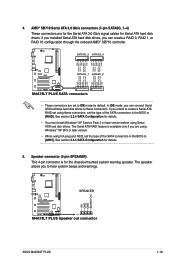
... to these connectors, set to hear system beeps and warnings. +5V GND GND Speaker Out SPEAKER M4A78LT PLUS PIN 1 M4A78LT PLUS Speaker out connector ASUS M4A78LT PLUS 1-19 See section 2.3.4 SATA Configuration for the chassis-mounted system warning speaker. 4. Speaker connector (4-...RSATA_TXN4 GND RSATA_RXP4 RSATA_RXN4 GND GND RSATA_RXN1 RSATA_RXP1 GND RSATA_TXN1 RSATA_TXP1 GND GND RSATA_RXN2 RSATA_RXP2 GND RSATA_TXN2 RSATA_TXP2 GND M4A78LT PLUS SATA3G_1 SATA3G_2 M4A78LT PLUS SATA connectors • These connectors are for the Serial ATA 3.0 Gb/s signal cables for details. 5. ...
... to these connectors, set to hear system beeps and warnings. +5V GND GND Speaker Out SPEAKER M4A78LT PLUS PIN 1 M4A78LT PLUS Speaker out connector ASUS M4A78LT PLUS 1-19 See section 2.3.4 SATA Configuration for the chassis-mounted system warning speaker. 4. Speaker connector (4-...RSATA_TXN4 GND RSATA_RXP4 RSATA_RXN4 GND GND RSATA_RXN1 RSATA_RXP1 GND RSATA_TXN1 RSATA_TXP1 GND GND RSATA_RXN2 RSATA_RXP2 GND RSATA_TXN2 RSATA_TXP2 GND M4A78LT PLUS SATA3G_1 SATA3G_2 M4A78LT PLUS SATA connectors • These connectors are for the Serial ATA 3.0 Gb/s signal cables for details. 5. ...
User Manual
Page 30
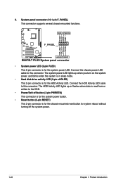
...chassis-mounted reset button for system reboot without turning off the system power. 1-20 Chapter 1: Product introduction PLED PWRBTN PLED+ PLEDPWR GND M4A78LT PLUS F_PANEL PIN 1 IDE_LED+ IDE_LED- Connect the chassis power LED cable to the HDD. • Power/Soft-off button (2-pin PWRBTN)... written to this connector. System panel connector (10-1 pin F_PANEL) This connector supports several chassis-mounted functions. Ground Reset +HDLED RESET M4A78LT PLUS System panel connector • System power LED (2-pin PLED) This 2-pin connector is for the system power LED. The HDD Activity...
...chassis-mounted reset button for system reboot without turning off the system power. 1-20 Chapter 1: Product introduction PLED PWRBTN PLED+ PLEDPWR GND M4A78LT PLUS F_PANEL PIN 1 IDE_LED+ IDE_LED- Connect the chassis power LED cable to the HDD. • Power/Soft-off button (2-pin PWRBTN)... written to this connector. System panel connector (10-1 pin F_PANEL) This connector supports several chassis-mounted functions. Ground Reset +HDLED RESET M4A78LT PLUS System panel connector • System power LED (2-pin PLED) This 2-pin connector is for the system power LED. The HDD Activity...


