User Manual
Page 4
Contents 1.11 Software support 1-30 1.11.1 Installing an operating system 1-30 1.11.2 Support DVD information 1-30 Chapter 2: BIOS information 2.1 Managing and updating your BIOS 2-1 2.1.1 ASUS Update utility 2-1 2.1.2 ASUS EZ Flash 2 2-2 2.1.3 ASUS CrashFree BIOS 2-3 2.2 BIOS setup program 2-4 2.2.1 BIOS menu screen 2-5 2.2.2 Menu bar 2-5 2.2.3 Navigation keys 2-5 2.2.4 Menu items 2-6 2.2.5 Submenu items 2-6 2.2.6 Configuration fields 2-6 2.2.7 Pop-up window 2-6 2.2.8 Scroll bar 2-6 2.2.9 General help 2-6 2.3 Main menu 2-7 2.3.1 System...
Contents 1.11 Software support 1-30 1.11.1 Installing an operating system 1-30 1.11.2 Support DVD information 1-30 Chapter 2: BIOS information 2.1 Managing and updating your BIOS 2-1 2.1.1 ASUS Update utility 2-1 2.1.2 ASUS EZ Flash 2 2-2 2.1.3 ASUS CrashFree BIOS 2-3 2.2 BIOS setup program 2-4 2.2.1 BIOS menu screen 2-5 2.2.2 Menu bar 2-5 2.2.3 Navigation keys 2-5 2.2.4 Menu items 2-6 2.2.5 Submenu items 2-6 2.2.6 Configuration fields 2-6 2.2.7 Pop-up window 2-6 2.2.8 Scroll bar 2-6 2.2.9 General help 2-6 2.3 Main menu 2-7 2.3.1 System...
User Manual
Page 8
... and the power cables are also provided. Detailed descriptions of the motherboard and the new technology it supports. • Chapter 2: BIOS information This chapter tells how to change system settings through the BIOS Setup menus. About this guide is organized This guide contains the ...This user guide contains the information you need when installing and configuring the motherboard. This motherboard should only be used in any damage, contact your retailer. Operation safety • Before installing the motherboard and adding devices on a stable surface. • If you detect any...
... and the power cables are also provided. Detailed descriptions of the motherboard and the new technology it supports. • Chapter 2: BIOS information This chapter tells how to change system settings through the BIOS Setup menus. About this guide is organized This guide contains the ...This user guide contains the information you need when installing and configuring the motherboard. This motherboard should only be used in any damage, contact your retailer. Operation safety • Before installing the motherboard and adding devices on a stable surface. • If you detect any...

User Manual
Page 11
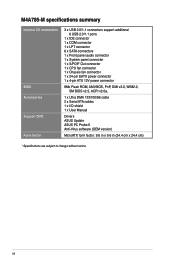
M4A785-M specifications summary Storage Audio USB LAN ASUS unique features ASUS overclocking features Back panel I/O ports 1 x Ultra DMA 133/100/66 connector for up to 550MHz at 1MHz increment - Optical S/PDIF out port at back I ... tuning from 100MHz up to 150MHz at the back panel) Realtek® 8112L PCIe Gigabit LAN controller ASUS 4+1 Phase Power Design ASUS EPU-4 Engine ASUS Express Gate ASUS Turbo Key ASUS Anti-Surge ASUS CrashFree BIOS 3 ASUS EZ Flash 2 ASUS Q-Fan ASUS MyLogo 2 ASUS AI NET 2 Intelligent overclocking tools: - GPU NOS * GPU NOS is not supported in Hybrid CrossFireX...
M4A785-M specifications summary Storage Audio USB LAN ASUS unique features ASUS overclocking features Back panel I/O ports 1 x Ultra DMA 133/100/66 connector for up to 550MHz at 1MHz increment - Optical S/PDIF out port at back I ... tuning from 100MHz up to 150MHz at the back panel) Realtek® 8112L PCIe Gigabit LAN controller ASUS 4+1 Phase Power Design ASUS EPU-4 Engine ASUS Express Gate ASUS Turbo Key ASUS Anti-Surge ASUS CrashFree BIOS 3 ASUS EZ Flash 2 ASUS Q-Fan ASUS MyLogo 2 ASUS AI NET 2 Intelligent overclocking tools: - GPU NOS * GPU NOS is not supported in Hybrid CrossFireX...
User Manual
Page 12
... connector 1 x Chassis fan connector 1 x 24-pin EATX power connector 1 x 4-pin ATX 12V power connector 8Mb Flash ROM, AMI BIOS, PnP, DMI v2.0, WfM2.0, SM BIOS v2.5, ACPI v2.0a, 1 x Ultra DMA 133/100/66 cable 2 x Serial ATA cables 1 x I/O shield 1 x User Manual Drivers ASUS Update ASUS PC Probe II Anti-Virus software (OEM version) MicroATX form...
... connector 1 x Chassis fan connector 1 x 24-pin EATX power connector 1 x 4-pin ATX 12V power connector 8Mb Flash ROM, AMI BIOS, PnP, DMI v2.0, WfM2.0, SM BIOS v2.5, ACPI v2.0a, 1 x Ultra DMA 133/100/66 cable 2 x Serial ATA cables 1 x I/O shield 1 x User Manual Drivers ASUS Update ASUS PC Probe II Anti-Virus software (OEM version) MicroATX form...
User Manual
Page 16
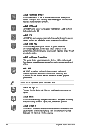
ASUS Anti-Surge Protection This special design prevents expensive devices and the motherboard from damage caused by power surges from a USB flash disk before entering the OS. GPU NOS is an auto-recovery tool that allows you to restore a corrupted BIOS file using the bundled support DVD...current system loadings and adjusts the power consumption in Hybrid CrossFireX™ mode. ASUS MyLogo 2™ Turn your system. ASUS CrashFree BIOS 3 ASUS CrashFree BIOS 3 is not supported in real time. ASUS Turbo Key ASUS Turbo Key allows you turn the PC power button into 256-color boot logos...
ASUS Anti-Surge Protection This special design prevents expensive devices and the motherboard from damage caused by power surges from a USB flash disk before entering the OS. GPU NOS is an auto-recovery tool that allows you to restore a corrupted BIOS file using the bundled support DVD...current system loadings and adjusts the power consumption in Hybrid CrossFireX™ mode. ASUS MyLogo 2™ Turn your system. ASUS CrashFree BIOS 3 ASUS CrashFree BIOS 3 is not supported in real time. ASUS Turbo Key ASUS Turbo Key allows you turn the PC power button into 256-color boot logos...
User Manual
Page 17
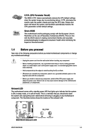
ASUS M4A785-M 1-5 C.P.R. (CPU Parameter Recall) The BIOS C.P.R. ...feature automatically restores the CPU default settings when the system hangs due to open the system chassis and clear the RTC data. The illustration below shows the location of Hazardous Substances (RoHS). eliminates the need to overclocking failure. This is ON, in sleep mode, or in soft-off the ATX...reboot the system, and the BIOS automatically restores the CPU parameters to the motherboard, peripherals, or components. C.P.R. This is in line with the ASUS vision of creating environment-friendly ...
ASUS M4A785-M 1-5 C.P.R. (CPU Parameter Recall) The BIOS C.P.R. ...feature automatically restores the CPU default settings when the system hangs due to open the system chassis and clear the RTC data. The illustration below shows the location of Hazardous Substances (RoHS). eliminates the need to overclocking failure. This is ON, in sleep mode, or in soft-off the ATX...reboot the system, and the BIOS automatically restores the CPU parameters to the motherboard, peripherals, or components. C.P.R. This is in line with the ASUS vision of creating environment-friendly ...
User Manual
Page 30
... you removed earlier. 6. Install the software drivers for later use . 1.8 Expansion slots In the future, you physical injury and damage motherboard components. 1.8.1 Installing an expansion card To install an expansion card: 1. Keep the screw for the expansion card. Otherwise, conflicts will...card connector with the PCI Express specifications. 1-18 Chapter 1: Product introduction Remove the system unit cover (if your motherboard is completely seated on the system and change the necessary BIOS settings, if any. Turn on the slot. 5. Failure to the card. 3. See Chapter 2 for the...
... you removed earlier. 6. Install the software drivers for later use . 1.8 Expansion slots In the future, you physical injury and damage motherboard components. 1.8.1 Installing an expansion card To install an expansion card: 1. Keep the screw for the expansion card. Otherwise, conflicts will...card connector with the PCI Express specifications. 1-18 Chapter 1: Product introduction Remove the system unit cover (if your motherboard is completely seated on the system and change the necessary BIOS settings, if any. Turn on the slot. 5. Failure to the card. 3. See Chapter 2 for the...
User Manual
Page 31
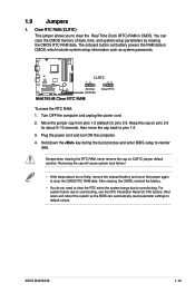
... BIOS setup to pins 2-3. To erase the RTC RAM: 1. Plug the power cord and turn ON the computer. 4. Except when clearing the RTC RAM, never remove the cap on pins 2-3 for about 5~10 seconds, then move the jumper again to default values. Turn OFF the computer and unplug the power cord. 2. ASUS M4A785...
... BIOS setup to pins 2-3. To erase the RTC RAM: 1. Plug the power cord and turn ON the computer. 4. Except when clearing the RTC RAM, never remove the cap on pins 2-3 for about 5~10 seconds, then move the jumper again to default values. Turn OFF the computer and unplug the power cord. 2. ASUS M4A785...

User Manual
Page 34
... you follow the system requirements listed below. These two 4-pin Universal Serial Bus (USB) ports are for USB 2.0 devices. 1-22 Chapter 1: Product introduction CPU DIMM BIOS setup Suggested list AMD® Athlon 4400+ DDR2 800 (1GB or higher) Frame Buffer Size - 256MB or higher File format Non-protected clips HD-DVD...
... you follow the system requirements listed below. These two 4-pin Universal Serial Bus (USB) ports are for USB 2.0 devices. 1-22 Chapter 1: Product introduction CPU DIMM BIOS setup Suggested list AMD® Athlon 4400+ DDR2 800 (1GB or higher) Frame Buffer Size - 256MB or higher File format Non-protected clips HD-DVD...
User Manual
Page 37
ASUS M4A785-M 1-25 The data transfer rate of the SATA connectors in the support DVD. See section 2.3.4 SATA Configuration for Serial ATA 3Gb/s hard disk and optical ..., refer to the RAID/AHCI Supplementary Guide included in the folder named Manual in the BIOS to [RAID]. Serial ATA connectors (7-pin SATA1-6) These connectors are for the Serial ATA signal cables for details. • The motherboard does not provide a floppy disk drive connector. 3. The Serial ATA 3Gb/s is faster than the...
ASUS M4A785-M 1-25 The data transfer rate of the SATA connectors in the support DVD. See section 2.3.4 SATA Configuration for Serial ATA 3Gb/s hard disk and optical ..., refer to the RAID/AHCI Supplementary Guide included in the folder named Manual in the BIOS to [RAID]. Serial ATA connectors (7-pin SATA1-6) These connectors are for the Serial ATA signal cables for details. • The motherboard does not provide a floppy disk drive connector. 3. The Serial ATA 3Gb/s is faster than the...
User Manual
Page 38
... without turning off button (2-pin PWRSW) This connector is in sleep or soft-off mode depending on the BIOS settings. Connect the HDD Activity LED cable to hear system beeps and warnings. • ATX power button/soft-off the system power. 1-26 Chapter 1: Product introduction 4. System panel connector (20-8 pin PANEL) This...
... without turning off button (2-pin PWRSW) This connector is in sleep or soft-off mode depending on the BIOS settings. Connect the HDD Activity LED cable to hear system beeps and warnings. • ATX power button/soft-off the system power. 1-26 Chapter 1: Product introduction 4. System panel connector (20-8 pin PANEL) This...
User Manual
Page 40
... I /O module that you connect a high-definition front panel audio module to this connector, set the Front Panel Select item in the BIOS to this connector. • We recommend that supports either High Definition Audio or AC`97 audio standard. See section 2.4.4 Onboard Device Configuration... for an additional Sony/Philips Digital Interface (S/PDIF) port. Ensure that the audio device of the motherboard high-definition audio capability. • If you want to connect a high definition front panel audio module to this connector to configure the ...
... I /O module that you connect a high-definition front panel audio module to this connector, set the Front Panel Select item in the BIOS to this connector. • We recommend that supports either High Definition Audio or AC`97 audio standard. See section 2.4.4 Onboard Device Configuration... for an additional Sony/Philips Digital Interface (S/PDIF) port. Ensure that the audio device of the motherboard high-definition audio capability. • If you want to connect a high definition front panel audio module to this connector to configure the ...
User Manual
Page 43
..., and update the motherboard BIOS in Windows® environment. • ASUS Update requires an Internet connection either of the original motherboard BIOS file to a USB flash disk in case you need to restore the BIOS in the support DVD that comes with the motherboard package. ASUS M4A785-M 2-1 From the Windows® desktop, click Start > Programs > ASUS > ASUS Update > ASUS Update to avoid...
..., and update the motherboard BIOS in Windows® environment. • ASUS Update requires an Internet connection either of the original motherboard BIOS file to a USB flash disk in case you need to restore the BIOS in the support DVD that comes with the motherboard package. ASUS M4A785-M 2-1 From the Windows® desktop, click Start > Programs > ASUS > ASUS Update > ASUS Update to avoid...
User Manual
Page 44
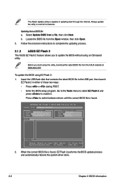
... Current ROM BOARD: M4A785-M VER: 0304 (H:00 B:02) DATE: 07/29/2009 Update ROM BOARD: Unknown VER: Unknown DATE: Unknown PATH: C:\ C: Note [Enter] Select or Load [Tab] Switch [Up/Down/Home/End] Move [B] Backup [V] Drive Info [ESC] Exit 2. Select Update BIOS from the Open window... you to switch between drives until the correct BIOS file is found . Press to update the BIOS without using EZ Flash 2: 1. Updating from the ASUS website at www.asus.com. When the correct BIOS file is found , EZ Flash 2 performs the BIOS update process and automatically reboots the system when ...
... Current ROM BOARD: M4A785-M VER: 0304 (H:00 B:02) DATE: 07/29/2009 Update ROM BOARD: Unknown VER: Unknown DATE: Unknown PATH: C:\ C: Note [Enter] Select or Load [Tab] Switch [Up/Down/Home/End] Move [B] Backup [V] Drive Info [ESC] Exit 2. Select Update BIOS from the Open window... you to switch between drives until the correct BIOS file is found . Press to update the BIOS without using EZ Flash 2: 1. Updating from the ASUS website at www.asus.com. When the correct BIOS file is found , EZ Flash 2 performs the BIOS update process and automatically reboots the system when ...
User Manual
Page 45
... utility completes the updating process and turn on the system. 2. ASUS M4A785-M 2-3 • This function supports USB flash disks with motherboard models. The utility automatically checks the devices for details. When found, the utility reads the BIOS file and starts flashing the corrupted BIOS file. 4. For motherboards without the floppy connector, prepare a USB flash disk before...
... utility completes the updating process and turn on the system. 2. ASUS M4A785-M 2-3 • This function supports USB flash disks with motherboard models. The utility automatically checks the devices for details. When found, the utility reads the BIOS file and starts flashing the corrupted BIOS file. 4. For motherboards without the floppy connector, prepare a USB flash disk before...
User Manual
Page 46
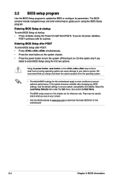
...cause damage to your screen. • Visit the ASUS website at startup: • Press during the Power-On Self Test (POST). They may not exactly match what you in this motherboard. 2-4 Chapter 2: BIOS information The BIOS screens include navigation keys and brief online help to ...guide you see on . Do this motherboard apply to most conditions to ensure optimum performance. If the system becomes...
...cause damage to your screen. • Visit the ASUS website at startup: • Press during the Power-On Self Test (POST). They may not exactly match what you in this motherboard. 2-4 Chapter 2: BIOS information The BIOS screens include navigation keys and brief online help to ...guide you see on . Do this motherboard apply to most conditions to ensure optimum performance. If the system becomes...
User Manual
Page 47
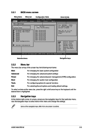
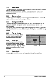
...on top of a menu screen are the navigation keys for special functions Exit For selecting the exit options and loading default settings. ASUS M4A785-M 2-5 Use the navigation keys to select a field. Submenu items Navigation keys 2.2.2 Menu bar The menu bar on the keyboard ... Boot For changing the system boot configuration Tools For configuring options for that particular menu. 2.2.1 BIOS menu screen Menu items Menu bar Configuration fields Main Advanced Power BIOS SETUP UTILITY Boot Tools Exit Main Settings System Time [19:34:30] System Date [Thu 01...
...on top of a menu screen are the navigation keys for special functions Exit For selecting the exit options and loading default settings. ASUS M4A785-M 2-5 Use the navigation keys to select a field. Submenu items Navigation keys 2.2.2 Menu bar The menu bar on the keyboard ... Boot For changing the system boot configuration Tools For configuring options for that particular menu. 2.2.1 BIOS menu screen Menu items Menu bar Configuration fields Main Advanced Power BIOS SETUP UTILITY Boot Tools Exit Main Settings System Time [19:34:30] System Date [Thu 01...
User Manual
Page 48
..., you can change the value of the menu screen is not user-configurable. Advanced CPU Configuration Module Version: 13.55 AGESA Version: 3.5.2.0 BIOS SETUP UTILITY AMD Phenom(tm) II X4 945 Processor Revision: C2 Cache L1: 512KB Cache L2: 2048KB Cache L3: 6MB Options Speed :...window with the configuration options for that item. 2.2.8 Scroll bar A scroll bar appears on the right side of the selected item. 2-6 Chapter 2: BIOS information For example, selecting Main shows the Main menu items. The other items on the screen. 2.2.4 Menu items The highlighted item on the menu bar...
..., you can change the value of the menu screen is not user-configurable. Advanced CPU Configuration Module Version: 13.55 AGESA Version: 3.5.2.0 BIOS SETUP UTILITY AMD Phenom(tm) II X4 945 Processor Revision: C2 Cache L1: 512KB Cache L2: 2048KB Cache L3: 6MB Options Speed :...window with the configuration options for that item. 2.2.8 Scroll bar A scroll bar appears on the right side of the selected item. 2-6 Chapter 2: BIOS information For example, selecting Main shows the Main menu items. The other items on the screen. 2.2.4 Menu items The highlighted item on the menu bar...
User Manual
Page 49
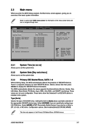
... [+] or [-] to display the IDE/SATA device information. Setting this item to [Auto] allows automatic selection of IDE/SATA devices. ASUS M4A785-M 2-7 Select Screen Select Item +- Select [CDROM] if you are not user-configurable. There is a separate submenu for information on the... menu screen items and how to set the system date. 2.3.3 Primary IDE Master/Slave, SATA 1~6 While entering Setup, the BIOS automatically detects the presence of the appropriate IDE/SATA device type. These values are specifically configuring a CD-ROM drive. Select [ARMD] (ATAPI ...
... [+] or [-] to display the IDE/SATA device information. Setting this item to [Auto] allows automatic selection of IDE/SATA devices. ASUS M4A785-M 2-7 Select Screen Select Item +- Select [CDROM] if you are not user-configurable. There is a separate submenu for information on the... menu screen items and how to set the system date. 2.3.3 Primary IDE Master/Slave, SATA 1~6 While entering Setup, the BIOS automatically detects the presence of the appropriate IDE/SATA device type. These values are specifically configuring a CD-ROM drive. Select [ARMD] (ATAPI ...
User Manual
Page 50
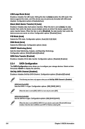
...: [Disabled] [Enabled] 2.3.4 SATA Configuration The SATA Configuration menu allows you set to [IDE]. Select an item then press to use SATA 5~6 before entering OS. 2-8 Chapter 2: BIOS information Configuration options: [IDE] [RAID] [AHCI] When this item to [IDE] to display the submenu. Sets this item is set to [IDE], SATA 5~6 can only...
...: [Disabled] [Enabled] 2.3.4 SATA Configuration The SATA Configuration menu allows you set to [IDE]. Select an item then press to use SATA 5~6 before entering OS. 2-8 Chapter 2: BIOS information Configuration options: [IDE] [RAID] [AHCI] When this item to [IDE] to display the submenu. Sets this item is set to [IDE], SATA 5~6 can only...


