
User Manual
Page 1
M4A77 Motherboard
M4A77 Motherboard
User Manual
Page 3
Contents Notices...vi Safety information vii About this guide vii M4A77 specifications summary ix Chapter 1: Product introduction 1.1 Welcome 1-1 1.2 Package contents 1-1 1.3 Special features 1-1 1.3.1 Product highlights 1-1 1.3.2 Innovative ASUS features 1-3 1.4 Before you proceed 1-5 1.5 Motherboard overview 1-6 1.5.1 Placement direction 1-6 1.5.2 Screw holes 1-6 1.5.3 Motherboard layout 1-7 1.5.4 Layout contents 1-7 1.6 Central Processing Unit (CPU 1-8 1.6.1 Installing the CPU 1-8 1.6.2 Installing the heatsink and fan 1-10 1.7 System memory...
Contents Notices...vi Safety information vii About this guide vii M4A77 specifications summary ix Chapter 1: Product introduction 1.1 Welcome 1-1 1.2 Package contents 1-1 1.3 Special features 1-1 1.3.1 Product highlights 1-1 1.3.2 Innovative ASUS features 1-3 1.4 Before you proceed 1-5 1.5 Motherboard overview 1-6 1.5.1 Placement direction 1-6 1.5.2 Screw holes 1-6 1.5.3 Motherboard layout 1-7 1.5.4 Layout contents 1-7 1.6 Central Processing Unit (CPU 1-8 1.6.1 Installing the CPU 1-8 1.6.2 Installing the heatsink and fan 1-10 1.7 System memory...
User Manual
Page 6
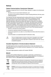
...Registration, Evaluation, Authorisation, and Restriction of Chemicals) regulatory framework, we published the chemical substances in our products at ASUS REACH website at http://green.asus.com/english/REACH.htm. DO NOT throw the mercury-containing button cell battery in the Radio Interference Regulations of the...wheeled bin indicates that the battery should not be placed in accordance with Part 15 of the FCC Rules. DO NOT throw the motherboard in a residential installation. Operation is no guarantee that may not cause harmful interference, and • This device must accept any...
...Registration, Evaluation, Authorisation, and Restriction of Chemicals) regulatory framework, we published the chemical substances in our products at ASUS REACH website at http://green.asus.com/english/REACH.htm. DO NOT throw the mercury-containing button cell battery in the Radio Interference Regulations of the...wheeled bin indicates that the battery should not be placed in accordance with Part 15 of the FCC Rules. DO NOT throw the motherboard in a residential installation. Operation is no guarantee that may not cause harmful interference, and • This device must accept any...
User Manual
Page 7
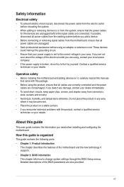
...connectors, slots, sockets and circuitry. • Avoid dust, humidity, and temperature extremes. If you are not sure about the voltage of the motherboard and the new technology it may become wet. • Place the product on it by yourself. How this guide This user guide contains ... all cables are correctly connected and the power cables are using an adapter or extension cord. If you need when installing and configuring the motherboard. Contact a qualified service technician or your area. About this guide is set to the correct voltage in any damage, contact your dealer ...
...connectors, slots, sockets and circuitry. • Avoid dust, humidity, and temperature extremes. If you are not sure about the voltage of the motherboard and the new technology it may become wet. • Place the product on it by yourself. How this guide This user guide contains ... all cables are correctly connected and the power cables are using an adapter or extension cord. If you need when installing and configuring the motherboard. Contact a qualified service technician or your area. About this guide is set to the correct voltage in any damage, contact your dealer ...
User Manual
Page 11
... 5200MT/s via HyperTransport™ 3.0based system bus. Thank you start installing the motherboard, and hardware devices on it another standout in the new 45nm manufacturing process. This motherboard also supports AMD® CPUs in the long line of the above items is damaged or missing, contact your motherboard package for buying an ASUS® M4A77 motherboard! ASUS M4A77 1-1
... 5200MT/s via HyperTransport™ 3.0based system bus. Thank you start installing the motherboard, and hardware devices on it another standout in the new 45nm manufacturing process. This motherboard also supports AMD® CPUs in the long line of the above items is damaged or missing, contact your motherboard package for buying an ASUS® M4A77 motherboard! ASUS M4A77 1-1
User Manual
Page 12
..., data transfer rate up to provide excellent system performance and overclocking capabilities. AMD Cool 'n' Quiet Technology This motherboard supports the AMD Cool 'n' Quiet technology which monitors system operation and automatically adjusts CPU voltage and frequency for ...increase memory computing efficiency, enhancing system performance in 3D graphics and other memory demanding applications. S/PDIF digital sound ready This motherboard provides convenient connectivity to 5200MT/s via coaxial and optical S/PDIF_OUT (SONYPHILIPS Digital Interface) jacks. HyperTransport™ 3.0 support...
..., data transfer rate up to provide excellent system performance and overclocking capabilities. AMD Cool 'n' Quiet Technology This motherboard supports the AMD Cool 'n' Quiet technology which monitors system operation and automatically adjusts CPU voltage and frequency for ...increase memory computing efficiency, enhancing system performance in 3D graphics and other memory demanding applications. S/PDIF digital sound ready This motherboard provides convenient connectivity to 5200MT/s via coaxial and optical S/PDIF_OUT (SONYPHILIPS Digital Interface) jacks. HyperTransport™ 3.0 support...
User Manual
Page 13
...to provide efficient power management for advanced operating systems. PCI Express 2.0 support This motherboard supports PCI Express 2.0 devices for Express Gate source codes. Refer to support.asus.com for double speed and bandwidth which means there will be no more confusion of... entering the Windows® OS. • ASUS Express Gate supports installation on the system configuration. • ASUS Express Gate supports file uploading from SATA HDDs, ODDs and USB drives. ASUS M4A77 1-3 Innovative ASUS features ASUS Express Gate ASUS Express Gate is enhanced with the OpenGL standard....
...to provide efficient power management for advanced operating systems. PCI Express 2.0 support This motherboard supports PCI Express 2.0 devices for Express Gate source codes. Refer to support.asus.com for double speed and bandwidth which means there will be no more confusion of... entering the Windows® OS. • ASUS Express Gate supports installation on the system configuration. • ASUS Express Gate supports file uploading from SATA HDDs, ODDs and USB drives. ASUS M4A77 1-3 Innovative ASUS features ASUS Express Gate ASUS Express Gate is enhanced with the OpenGL standard....
User Manual
Page 14
... is in real time. eliminates the need to overclocking failure. Green ASUS This motherboard and its packaging comply with the ASUS vision of Hazardous Substances (RoHS). This is a unique power saving technology that detects the current system loadings and adjusts the power ...the system, and the BIOS automatically restores the CPU parameters to update the BIOS from a USB flash disk before entering the OS. C.P.R. ASUS EZ Flash 2 ASUS EZ Flash 2 allows you to their default settings. After the easy setup, Turbo Key boosts performances without interrupting ongoing work or games, ...
... is in real time. eliminates the need to overclocking failure. Green ASUS This motherboard and its packaging comply with the ASUS vision of Hazardous Substances (RoHS). This is a unique power saving technology that detects the current system loadings and adjusts the power ...the system, and the BIOS automatically restores the CPU parameters to update the BIOS from a USB flash disk before entering the OS. C.P.R. ASUS EZ Flash 2 ASUS EZ Flash 2 allows you to their default settings. After the easy setup, Turbo Key boosts performances without interrupting ongoing work or games, ...
User Manual
Page 15
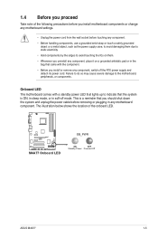
... SB_PWR ON OFF Standby Power Powered Off ASUS M4A77 1-5 Onboard LED The motherboard comes with a standby power LED that lights up to indicate that the system is a reminder that came with the component. • Before you install or ... the power cable before touching any component, switch off mode. The illustration below shows the location of the following precautions before you install motherboard components or change any motherboard settings. • Unplug the power cord from the wall socket before removing or plugging in any component, place it on a grounded antistatic ...
... SB_PWR ON OFF Standby Power Powered Off ASUS M4A77 1-5 Onboard LED The motherboard comes with a standby power LED that lights up to indicate that the system is a reminder that came with the component. • Before you install or ... the power cable before touching any component, switch off mode. The illustration below shows the location of the following precautions before you install motherboard components or change any motherboard settings. • Unplug the power cord from the wall socket before removing or plugging in any component, place it on a grounded antistatic ...
User Manual
Page 16
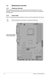
Place this side towards the rear of the chassis as indicated in the image below. 1.5.2 Screw holes Place six screws into the chassis in the correct orientation. Doing so can damage the motherboard. DO NOT overtighten the screws! The edge with external ports goes to the rear part of the chassis. M4A77 1-6 Chapter 1: Product introduction 1.5 Motherboard overview 1.5.1 Placement direction When installing the motherboard, ensure that you place it into the holes indicated by circles to secure the motherboard to the chassis.
Place this side towards the rear of the chassis as indicated in the image below. 1.5.2 Screw holes Place six screws into the chassis in the correct orientation. Doing so can damage the motherboard. DO NOT overtighten the screws! The edge with external ports goes to the rear part of the chassis. M4A77 1-6 Chapter 1: Product introduction 1.5 Motherboard overview 1.5.1 Placement direction When installing the motherboard, ensure that you place it into the holes indicated by circles to secure the motherboard to the chassis.
User Manual
Page 17
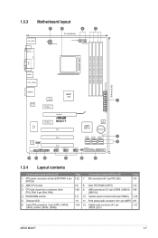
...4-pin ATX12V) 2. USB connectors (10-1 pin USB78, USB910, 1-26 USB1112) 10. AMD CPU socket 3. 1.5.3 Motherboard layout 1 2 3 4 21.4cm(8.4in) KB_USB56 ATX12V CPU_FAN CHA_FAN SPDIF_O SOCKET AM2+ DDR2 DIMM_A1 (64bit, 240-... COM LPT USB34 LAN1_USB12 AUDIO AMD® 770 ICS 9LPRS482 1 Realtek RTL8112L PCIEX1_1 PCIEX16 Super I/O PCIEX1_2 M4A77 PCI1 AMD® SB710 8Mb BIOS Lithium Cell CMOS Power VIA SPDIF_OUT VT1818S AAFP PANEL PCI2 SB_PWR SATA1...IDE connector (40-1 pin PRI_IDE) Page 1-23 8. Digital audio connector (4-1 pin 1-27 SPDIF_OUT) ASUS M4A77 1-7
...4-pin ATX12V) 2. USB connectors (10-1 pin USB78, USB910, 1-26 USB1112) 10. AMD CPU socket 3. 1.5.3 Motherboard layout 1 2 3 4 21.4cm(8.4in) KB_USB56 ATX12V CPU_FAN CHA_FAN SPDIF_O SOCKET AM2+ DDR2 DIMM_A1 (64bit, 240-... COM LPT USB34 LAN1_USB12 AUDIO AMD® 770 ICS 9LPRS482 1 Realtek RTL8112L PCIEX1_1 PCIEX16 Super I/O PCIEX1_2 M4A77 PCI1 AMD® SB710 8Mb BIOS Lithium Cell CMOS Power VIA SPDIF_OUT VT1818S AAFP PANEL PCI2 SB_PWR SATA1...IDE connector (40-1 pin PRI_IDE) Page 1-23 8. Digital audio connector (4-1 pin 1-27 SPDIF_OUT) ASUS M4A77 1-7
User Manual
Page 18
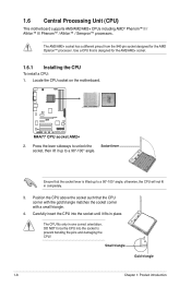
...pin socket designed for the AM2/AM2+ socket. 1.6.1 Installing the CPU To install a CPU: 1. Locate the CPU socket on the motherboard. Ensure that the socket lever is designed for the AMD Opteron™ processor. DO NOT force the CPU into the socket until ... Gold triangle 1-8 Chapter 1: Product introduction 1.6 Central Processing Unit (CPU) This motherboard supports AM3/AM2/AM2+ CPUs including AMD® Phenom™ II / Athlon™ II/ Phenom™ / Athlon™ / Sempron™ processors. M4A77 M4A77 CPU socket AM2+ 2. otherwise, the CPU will not fit in one correct ...
...pin socket designed for the AM2/AM2+ socket. 1.6.1 Installing the CPU To install a CPU: 1. Locate the CPU socket on the motherboard. Ensure that the socket lever is designed for the AMD Opteron™ processor. DO NOT force the CPU into the socket until ... Gold triangle 1-8 Chapter 1: Product introduction 1.6 Central Processing Unit (CPU) This motherboard supports AM3/AM2/AM2+ CPUs including AMD® Phenom™ II / Athlon™ II/ Phenom™ / Athlon™ / Sempron™ processors. M4A77 M4A77 CPU socket AM2+ 2. otherwise, the CPU will not fit in one correct ...
User Manual
Page 19
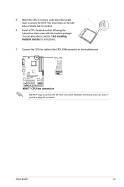
The lever clicks on the motherboard. You can occur if you fail to secure the CPU. CPU_FAN M4A77 M4A77 CPU fan connector DO NOT forget to section 1.6.2 Installing heatsink and fan for instructions. 7. GND CPU FAN PWR CPU FAN IN CPU FAN PWM ASUS M4A77 1-9 Install a CPU heatsink and fan following the instructions that it is...
The lever clicks on the motherboard. You can occur if you fail to secure the CPU. CPU_FAN M4A77 M4A77 CPU fan connector DO NOT forget to section 1.6.2 Installing heatsink and fan for instructions. 7. GND CPU FAN PWR CPU FAN IN CPU FAN PWM ASUS M4A77 1-9 Install a CPU heatsink and fan following the instructions that it is...
User Manual
Page 20
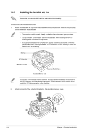
.... • If you purchased a separate CPU heatsink and fan assembly, ensure that a Thermal Interface Material is already installed on the motherboard upon purchase. • You do not match the CPU documentation, follow the latter. 2. 1.6.2 Installing the heatsink and fan Ensure that you install the heatsink and ...
.... • If you purchased a separate CPU heatsink and fan assembly, ensure that a Thermal Interface Material is already installed on the motherboard upon purchase. • You do not match the CPU documentation, follow the latter. 2. 1.6.2 Installing the heatsink and fan Ensure that you install the heatsink and ...
User Manual
Page 21
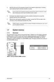
...place. Align the other end of the DDR2 DIMM sockets: DIMM_A1 DIMM_B1 DIMM_A2 DIMM_B2 M4A77 M4A77 240-pin DDR2 DIMM sockets Channel Channel A Channel B Sockets DIMM_A1 and DIMM_A2 DIMM_B1 and DIMM_B2 ASUS M4A77 1-11 A clicking sound denotes that the fan and heatsink assembly perfectly fits the... on a DDR DIMM socket. The figure illustrates the location of the retention bracket to plug this connector. 1.7 System memory 1.7.1 Overview The motherboard comes with four Double Data Rate 2 (DDR2) Dual Inline Memory Modules (DIMM) sockets. Ensure that the retention bracket is in place. ...
...place. Align the other end of the DDR2 DIMM sockets: DIMM_A1 DIMM_B1 DIMM_A2 DIMM_B2 M4A77 M4A77 240-pin DDR2 DIMM sockets Channel Channel A Channel B Sockets DIMM_A1 and DIMM_A2 DIMM_B1 and DIMM_B2 ASUS M4A77 1-11 A clicking sound denotes that the fan and heatsink assembly perfectly fits the... on a DDR DIMM socket. The figure illustrates the location of the retention bracket to plug this connector. 1.7 System memory 1.7.1 Overview The motherboard comes with four Double Data Rate 2 (DDR2) Dual Inline Memory Modules (DIMM) sockets. Ensure that the retention bracket is in place. ...
User Manual
Page 22
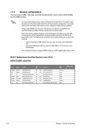
...; · · · · · 1-12 Chapter 1: Product introduction The system maps the total size of 256 megabits (Mb) chips or less. M4A77 Motherboard Qualified Vendors Lists (QVL) DDR2-533MHz capability Size Vendor Part No. 1.7.2 Memory configurations You may install 512MB, 1GB, 2GB, and 4GB unbuffered ECC and non... the memory address limitation on 32-bit Windows® OS, when you want to install 4GB or more memory on the motherboard. • This motherboard does not support DIMMs made up of the lower-sized channel for the OS can be about 3GB or less. SS/ DS...
...; · · · · · 1-12 Chapter 1: Product introduction The system maps the total size of 256 megabits (Mb) chips or less. M4A77 Motherboard Qualified Vendors Lists (QVL) DDR2-533MHz capability Size Vendor Part No. 1.7.2 Memory configurations You may install 512MB, 1GB, 2GB, and 4GB unbuffered ECC and non... the memory address limitation on 32-bit Windows® OS, when you want to install 4GB or more memory on the motherboard. • This motherboard does not support DIMMs made up of the lower-sized channel for the OS can be about 3GB or less. SS/ DS...

User Manual
Page 27
... clips outward to both the motherboard and the components. 1. Align a DIMM on the socket such that the notch on the DIMM matches the break on the socket. 2 DIMM notch 1 1 Unlocked retaining clip A DIMM is properly seated. Locked Retaining Clip 1.7.4 Removing a DIMM To remove a DIMM: 1. DIMM notch ASUS M4A77 1-17 1.7.3 Installing a DIMM Unplug the...
... clips outward to both the motherboard and the components. 1. Align a DIMM on the socket such that the notch on the DIMM matches the break on the socket. 2 DIMM notch 1 1 Unlocked retaining clip A DIMM is properly seated. Locked Retaining Clip 1.7.4 Removing a DIMM To remove a DIMM: 1. DIMM notch ASUS M4A77 1-17 1.7.3 Installing a DIMM Unplug the...
User Manual
Page 28
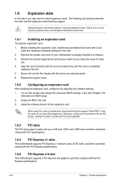
...such as a LAN card, SCSI card, USB card, and other cards that comply with PCI specifications. 1.8.4 PCI Express x1 slots This motherboard supports PCI Express x1 network cards, SCSI cards, and other cards that comply with the PCI Express specifications. 1-18 Chapter 1: Product ... support. Install the software drivers for later use . 1.8 Expansion slots In the future, you may cause you physical injury and damage motherboard components. 1.8.1 Installing an expansion card To install an expansion card: 1. The following sub‑sections describe the slots and the expansion ...
...such as a LAN card, SCSI card, USB card, and other cards that comply with PCI specifications. 1.8.4 PCI Express x1 slots This motherboard supports PCI Express x1 network cards, SCSI cards, and other cards that comply with the PCI Express specifications. 1-18 Chapter 1: Product ... support. Install the software drivers for later use . 1.8 Expansion slots In the future, you may cause you physical injury and damage motherboard components. 1.8.1 Installing an expansion card To install an expansion card: 1. The following sub‑sections describe the slots and the expansion ...
User Manual
Page 33
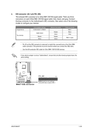
There are three connectors on the Ultra DMA cable connector. Connect the blue connector to the motherboard's IDE connector, then select one of the following modes to PIN 1. ASUS M4A77 1-23 IDE connector (40-1 pin PRI_IDE) The onboard IDE connector is set as "Cable-Select", ensure that all other ... the IDE connector is removed to match the covered hole on each Ultra DMA 133/100 signal cable: blue, black, and gray. M4A77 M4A77 IDE connector PRI_IDE PIN1 NOTE:Orient the red markings on the IDE ribbon cable to configure your devices: Single device Two devices Drive jumper...
There are three connectors on the Ultra DMA cable connector. Connect the blue connector to the motherboard's IDE connector, then select one of the following modes to PIN 1. ASUS M4A77 1-23 IDE connector (40-1 pin PRI_IDE) The onboard IDE connector is set as "Cable-Select", ensure that all other ... the IDE connector is removed to match the covered hole on each Ultra DMA 133/100 signal cable: blue, black, and gray. M4A77 M4A77 IDE connector PRI_IDE PIN1 NOTE:Orient the red markings on the IDE ribbon cable to configure your devices: Single device Two devices Drive jumper...
User Manual
Page 34
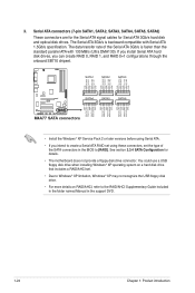
...RSATA_TXP4 RSATA_TXN4 GND RSATA_RXP4 RSATA_RXN4 GND GND RSATA_TXP5 RSATA_TXN5 GND RSATA_RXP5 RSATA_RXN5 GND GND RSATA_TXP6 RSATA_TXN6 GND RSATA_RXP6 RSATA_RXN6 GND SATA4 SATA5 SATA6 M4A77 M4A77 SATA connectors • Install the Windows® XP Service Pack 2 or later versions before using Serial ATA. • ...pin SATA1, SATA2, SATA3, SATA4, SATA5, SATA6) These connectors are for the Serial ATA signal cables for details. • The motherboard does not provide a floppy disk drive connector. You could use a USB floppy disk drive when installing Windows® XP operating system on...
...RSATA_TXP4 RSATA_TXN4 GND RSATA_RXP4 RSATA_RXN4 GND GND RSATA_TXP5 RSATA_TXN5 GND RSATA_RXP5 RSATA_RXN5 GND GND RSATA_TXP6 RSATA_TXN6 GND RSATA_RXP6 RSATA_RXN6 GND SATA4 SATA5 SATA6 M4A77 M4A77 SATA connectors • Install the Windows® XP Service Pack 2 or later versions before using Serial ATA. • ...pin SATA1, SATA2, SATA3, SATA4, SATA5, SATA6) These connectors are for the Serial ATA signal cables for details. • The motherboard does not provide a floppy disk drive connector. You could use a USB floppy disk drive when installing Windows® XP operating system on...


