User Manual
Page 11
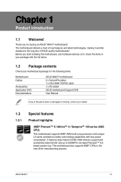
... series (AM3 CPU) This motherboard supports AMD® AM3 multi-core processors with unique L3 cache and delivers better overclocking capabilities with less power consumption. ASUS M4A77 1-1 It features dual-channel DDR2 1066 memory support and accelerates data transfer rate up to 5200MT/s via HyperTransport™ 3.0based system bus. This motherboard also...
... series (AM3 CPU) This motherboard supports AMD® AM3 multi-core processors with unique L3 cache and delivers better overclocking capabilities with less power consumption. ASUS M4A77 1-1 It features dual-channel DDR2 1066 memory support and accelerates data transfer rate up to 5200MT/s via HyperTransport™ 3.0based system bus. This motherboard also...
User Manual
Page 13
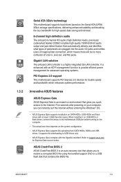
... feature that allows you to the motherboard USB port before turning on the computer. • The actual boot time depends on the system configuration. • ASUS Express Gate supports file uploading from SATA HDDs, ODDs and USB drives. Five seconds after powering on your computer, you quick access to USB drives... for double speed and bandwidth which means there will be no more confusion of Line-in, Line-out, and Mic jacks. ASUS M4A77 1-3 When installing it on USB HDDs or flash drives, connect the drives to restore a corrupted BIOS file using the bundled support DVD or a USB flash ...
... feature that allows you to the motherboard USB port before turning on the computer. • The actual boot time depends on the system configuration. • ASUS Express Gate supports file uploading from SATA HDDs, ODDs and USB drives. Five seconds after powering on your computer, you quick access to USB drives... for double speed and bandwidth which means there will be no more confusion of Line-in, Line-out, and Mic jacks. ASUS M4A77 1-3 When installing it on USB HDDs or flash drives, connect the drives to restore a corrupted BIOS file using the bundled support DVD or a USB flash ...
User Manual
Page 15
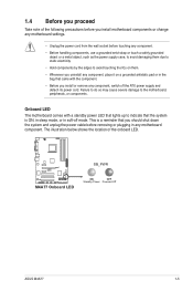
... them. • Whenever you uninstall any component, place it on a grounded antistatic pad or in any component, switch off mode. M4A77 M4A77 Onboard LED SB_PWR ON OFF Standby Power Powered Off ASUS M4A77 1-5 Onboard LED The motherboard comes with the component. • Before you should shut down the system and unplug the power cable...
... them. • Whenever you uninstall any component, place it on a grounded antistatic pad or in any component, switch off mode. M4A77 M4A77 Onboard LED SB_PWR ON OFF Standby Power Powered Off ASUS M4A77 1-5 Onboard LED The motherboard comes with the component. • Before you should shut down the system and unplug the power cable...
User Manual
Page 17
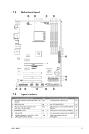
...Page 1-22 1-8 1-28 1-11 1-5 1-24 Connectors/Jumpers/Slots/LED 7. Clear RTC RAM (CLRTC) 1-19 9. Digital audio connector (4-1 pin 1-27 SPDIF_OUT) ASUS M4A77 1-7 DDR2 DIMM sockets 5. System panel connector (20-8 pin PANEL) 1-25 11. Front panel audio connector (10-1 pin AAFP) 1-27 12. AMD CPU ...30.5cm(12.0in) COM LPT USB34 LAN1_USB12 AUDIO AMD® 770 ICS 9LPRS482 1 Realtek RTL8112L PCIEX1_1 PCIEX16 Super I/O PCIEX1_2 M4A77 PCI1 AMD® SB710 8Mb BIOS Lithium Cell CMOS Power VIA SPDIF_OUT VT1818S AAFP PANEL PCI2 SB_PWR SATA1 SATA2 SATA3 5 SATA4...
...Page 1-22 1-8 1-28 1-11 1-5 1-24 Connectors/Jumpers/Slots/LED 7. Clear RTC RAM (CLRTC) 1-19 9. Digital audio connector (4-1 pin 1-27 SPDIF_OUT) ASUS M4A77 1-7 DDR2 DIMM sockets 5. System panel connector (20-8 pin PANEL) 1-25 11. Front panel audio connector (10-1 pin AAFP) 1-27 12. AMD CPU ...30.5cm(12.0in) COM LPT USB34 LAN1_USB12 AUDIO AMD® 770 ICS 9LPRS482 1 Realtek RTL8112L PCIEX1_1 PCIEX16 Super I/O PCIEX1_2 M4A77 PCI1 AMD® SB710 8Mb BIOS Lithium Cell CMOS Power VIA SPDIF_OUT VT1818S AAFP PANEL PCI2 SB_PWR SATA1 SATA2 SATA3 5 SATA4...
User Manual
Page 19
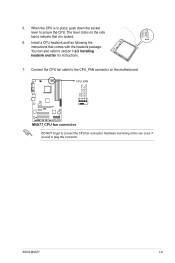
5. GND CPU FAN PWR CPU FAN IN CPU FAN PWM ASUS M4A77 1-9 Connect the CPU fan cable to the CPU_FAN connector on the side tab to indicate that comes with the heatsink package. Hardware monitoring errors can ... that it is in place, push down the socket lever to section 1.6.2 Installing heatsink and fan for instructions. 7. The lever clicks on the motherboard. CPU_FAN M4A77 M4A77 CPU fan connector DO NOT forget to plug this connector. When the CPU is locked. 6. You can occur if you fail to connect the CPU...
5. GND CPU FAN PWR CPU FAN IN CPU FAN PWM ASUS M4A77 1-9 Connect the CPU fan cable to the CPU_FAN connector on the side tab to indicate that comes with the heatsink package. Hardware monitoring errors can ... that it is in place, push down the socket lever to section 1.6.2 Installing heatsink and fan for instructions. 7. The lever clicks on the motherboard. CPU_FAN M4A77 M4A77 CPU fan connector DO NOT forget to plug this connector. When the CPU is locked. 6. You can occur if you fail to connect the CPU...
User Manual
Page 21
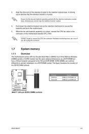
... 184-pin DDR DIMM. Align the other end of the DDR2 DIMM sockets: DIMM_A1 DIMM_B1 DIMM_A2 DIMM_B2 M4A77 M4A77 240-pin DDR2 DIMM sockets Channel Channel A Channel B Sockets DIMM_A1 and DIMM_A2 DIMM_B1 and DIMM_B2 ASUS M4A77 1-11 Push down the retention bracket lock on the retention mechanism to secure the heatsink and fan to...
... 184-pin DDR DIMM. Align the other end of the DDR2 DIMM sockets: DIMM_A1 DIMM_B1 DIMM_A2 DIMM_B2 M4A77 M4A77 240-pin DDR2 DIMM sockets Channel Channel A Channel B Sockets DIMM_A1 and DIMM_A2 DIMM_B1 and DIMM_B2 ASUS M4A77 1-11 Push down the retention bracket lock on the retention mechanism to secure the heatsink and fan to...

User Manual
Page 23
...; · · · · · · · · · · · · · · · · · · · · · · · · · ASUS M4A77 1-13 SS/ DS 2G Kingston KVR667D2N5/2G DS 512MB Kingston KVR667D2N5/512 SS 2G Kingston KVR667D2N5/2G DS 1G Kingston KVR667D2N5/1G DS 512MB Qimonda...
...; · · · · · · · · · · · · · · · · · · · · · · · · · ASUS M4A77 1-13 SS/ DS 2G Kingston KVR667D2N5/2G DS 512MB Kingston KVR667D2N5/512 SS 2G Kingston KVR667D2N5/2G DS 1G Kingston KVR667D2N5/1G DS 512MB Qimonda...

User Manual
Page 25
...; · · · · · · · · · · · · · · · · · · · · · · · · · ASUS M4A77 1-15 DDR2-800MHz capability Size Vendor Part No.
...; · · · · · · · · · · · · · · · · · · · · · · · · · ASUS M4A77 1-15 DDR2-800MHz capability Size Vendor Part No.

User Manual
Page 27
... outward to unlock a DIMM socket. 2. Align a DIMM on the socket such that it flips out with your fingers when pressing the retaining 1 clips. DIMM notch ASUS M4A77 1-17 Press the retaining clips outward to unlock the DIMM. 2 Support the DIMM lightly with extra force. 1 2. Remove the DIMM from the socket.
... outward to unlock a DIMM socket. 2. Align a DIMM on the socket such that it flips out with your fingers when pressing the retaining 1 clips. DIMM notch ASUS M4A77 1-17 Press the retaining clips outward to unlock the DIMM. 2 Support the DIMM lightly with extra force. 1 2. Remove the DIMM from the socket.
User Manual
Page 29
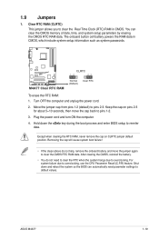
... RTC RAM Normal (Default) Clear RTC To erase the RTC RAM: 1. Plug the power cord and turn ON the computer. 4. ASUS M4A77 1-19 Except when clearing the RTC RAM, never remove the cap on pins 2-3 for about 5~10 seconds, then move the jumper again to pins 2-3. After ...
... RTC RAM Normal (Default) Clear RTC To erase the RTC RAM: 1. Plug the power cord and turn ON the computer. 4. ASUS M4A77 1-19 Except when clearing the RTC RAM, never remove the cap on pins 2-3 for about 5~10 seconds, then move the jumper again to pins 2-3. After ...

User Manual
Page 31
... (USB) ports are available for USB 2.0 devices. 11. Serial port. USB 2.0 ports 5 and 6. Refer to configure the settings. 10. Optical S/PDIF_OUT port. USB 2.0 ports 3 and 4. ASUS M4A77 1-21 This 9-pin COM1 port is VIA High Definition Audio (the name may be different based on the OS). This port connects to an external...
... (USB) ports are available for USB 2.0 devices. 11. Serial port. USB 2.0 ports 5 and 6. Refer to configure the settings. 10. Optical S/PDIF_OUT port. USB 2.0 ports 3 and 4. ASUS M4A77 1-21 This 9-pin COM1 port is VIA High Definition Audio (the name may be different based on the OS). This port connects to an external...
User Manual
Page 33
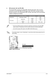
... configure your devices: Single device Two devices Drive jumper setting Cable-Select or Master Cable-Select Master Slave Mode of the following modes to PIN 1. ASUS M4A77 1-23 M4A77 M4A77 IDE connector PRI_IDE PIN1 NOTE:Orient the red markings on the Ultra DMA cable connector. 2. IDE connector (40-1 pin PRI_IDE) The onboard IDE connector...
... configure your devices: Single device Two devices Drive jumper setting Cable-Select or Master Cable-Select Master Slave Mode of the following modes to PIN 1. ASUS M4A77 1-23 M4A77 M4A77 IDE connector PRI_IDE PIN1 NOTE:Orient the red markings on the Ultra DMA cable connector. 2. IDE connector (40-1 pin PRI_IDE) The onboard IDE connector...
User Manual
Page 35
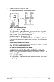
...-off button (2-pin PWRSW) This connector is for the chassis-mounted reset button for the system power button. ASUS M4A77 1-25 PWR Ground Reset Ground PANEL PIN 1 M4A77 IDE_LED PWRSW RESET * Requires an ATX power supply M4A77 System panel connector • System power LED (2-pin PLED) This 2-pin connector is for the system power...
...-off button (2-pin PWRSW) This connector is for the chassis-mounted reset button for the system power button. ASUS M4A77 1-25 PWR Ground Reset Ground PANEL PIN 1 M4A77 IDE_LED PWRSW RESET * Requires an ATX power supply M4A77 System panel connector • System power LED (2-pin PLED) This 2-pin connector is for the system power...
User Manual
Page 37
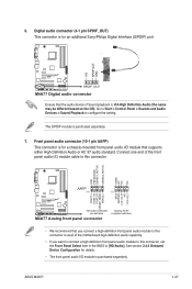
Connect one end of the front panel audio I/O module cable to configure the setting. ASUS M4A77 1-27 Go to Start > Control Panel > Sounds and Audio Devices > Sound Playback to this connector. The S/PDIF module is purchased separately. 6. Front panel... audio connector (10-1 pin AAFP) This connector is for an additional Sony/Philips Digital Interface (S/PDIF) port. +5V SPDIFOUT GND M4A77 SPDIF_OUT M4A77 Digital audio connector Ensure that the audio device of the motherboard high-definition audio capability. • If you want to connect a high definition front ...
Connect one end of the front panel audio I/O module cable to configure the setting. ASUS M4A77 1-27 Go to Start > Control Panel > Sounds and Audio Devices > Sound Playback to this connector. The S/PDIF module is purchased separately. 6. Front panel... audio connector (10-1 pin AAFP) This connector is for an additional Sony/Philips Digital Interface (S/PDIF) port. +5V SPDIFOUT GND M4A77 SPDIF_OUT M4A77 Digital audio connector Ensure that the audio device of the motherboard high-definition audio capability. • If you want to connect a high definition front ...
User Manual
Page 39
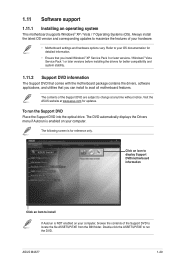
...support 1.11.1 Installing an operating system This motherboard supports Windows® XP / Vista / 7 Operating Systems (OS). To run the DVD. ASUS M4A77 1-29 Refer to install If Autorun is for reference only. The DVD automatically displays the Drivers menu if Autorun is enabled on your computer....Always install the latest OS version and corresponding updates to maximize the features of the Support DVD are subject to change at www.asus.com for better compatibility and system stability. 1.11.2 Support DVD information The Support DVD that comes with the motherboard package contains...
...support 1.11.1 Installing an operating system This motherboard supports Windows® XP / Vista / 7 Operating Systems (OS). To run the DVD. ASUS M4A77 1-29 Refer to install If Autorun is for reference only. The DVD automatically displays the Drivers menu if Autorun is enabled on your computer....Always install the latest OS version and corresponding updates to maximize the features of the Support DVD are subject to change at www.asus.com for better compatibility and system stability. 1.11.2 Support DVD information The Support DVD that comes with the motherboard package contains...
User Manual
Page 41
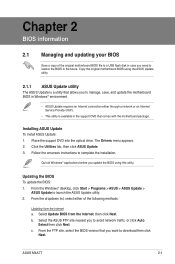
... comes with the motherboard package. Click the Utilities tab, then click ASUS Update. 3. Installing ASUS Update To install ASUS Update: 1. The Drivers menu appears. 2. ASUS M4A77 2-1 Quit all Windows® applications before you update the BIOS using the ASUS Update utility. 2.1.1 ASUS Update utility The ASUS Update is available in the support DVD that you to restore the...
... comes with the motherboard package. Click the Utilities tab, then click ASUS Update. 3. Installing ASUS Update To install ASUS Update: 1. The Drivers menu appears. 2. ASUS M4A77 2-1 Quit all Windows® applications before you update the BIOS using the ASUS Update utility. 2.1.1 ASUS Update utility The ASUS Update is available in the support DVD that you to restore the...
User Manual
Page 43
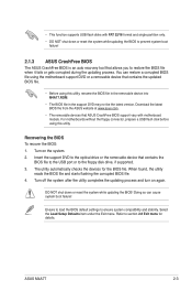
... BIOS! When found, the utility reads the BIOS file and starts flashing the corrupted BIOS file. 4. Recovering the BIOS To recover the BIOS: 1. ASUS M4A77 2-3 Insert the support DVD to the floppy disk drive, if supported. 3. DO NOT shut down or reset the system while updating the BIOS to...or the removable device that contains the updated BIOS file. • Before using this utility, rename the BIOS file in the removable device into M4A77.ROM. • The BIOS file in the support DVD may not be the latest version. Refer to ensure system compatibility and stability. Turn...
... BIOS! When found, the utility reads the BIOS file and starts flashing the corrupted BIOS file. 4. Recovering the BIOS To recover the BIOS: 1. ASUS M4A77 2-3 Insert the support DVD to the floppy disk drive, if supported. 3. DO NOT shut down or reset the system while updating the BIOS to...or the removable device that contains the updated BIOS file. • Before using this utility, rename the BIOS file in the removable device into M4A77.ROM. • The BIOS file in the support DVD may not be the latest version. Refer to ensure system compatibility and stability. Turn...
User Manual
Page 45
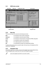
... the advanced power management (APM) configuration Boot For changing the system boot configuration Tools For configuring options for that particular menu. Select Screen Select Item +- ASUS M4A77 2-5 To select an item on the menu bar, press the right or left arrow key on top of a menu screen are the navigation keys for...
... the advanced power management (APM) configuration Boot For changing the system boot configuration Tools For configuring options for that particular menu. Select Screen Select Item +- ASUS M4A77 2-5 To select an item on the menu bar, press the right or left arrow key on top of a menu screen are the navigation keys for...
User Manual
Page 47
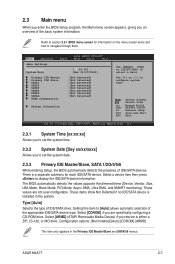
Setting this item to select a field. ASUS M4A77 2-7 Main Advanced Power BIOS SETUP UTILITY Boot Tools Exit Main Settings System Time [19:34:30] System Date [Mon 01/07/2002] Primary IDE Master ...
Setting this item to select a field. ASUS M4A77 2-7 Main Advanced Power BIOS SETUP UTILITY Boot Tools Exit Main Settings System Time [19:34:30] System Date [Mon 01/07/2002] Primary IDE Master ...
User Manual
Page 49
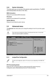
... Displays the auto-detected CPU specification. Take caution when changing the settings of the general system specifications. Configuration options: [Manual] [Auto] [Overclock Profile] [Test Mode] ASUS M4A77 2-9 Main Advanced Advanced Settings Power BIOS SETUP UTILITY Boot Tools Exit JumperFree Configuration CPU Configuration Chipset Onboard Devices Configuration PCIPnP USB Configuration Adjust System Frequency...
... Displays the auto-detected CPU specification. Take caution when changing the settings of the general system specifications. Configuration options: [Manual] [Auto] [Overclock Profile] [Test Mode] ASUS M4A77 2-9 Main Advanced Advanced Settings Power BIOS SETUP UTILITY Boot Tools Exit JumperFree Configuration CPU Configuration Chipset Onboard Devices Configuration PCIPnP USB Configuration Adjust System Frequency...


