
User Manual
Page 1
Motherboard
Motherboard

User Manual
Page 1
M3N78 SE Motherboard
M3N78 SE Motherboard
User Manual
Page 3
Contents Notices...vi Safety information vii About this guide vii M3N78 SE specifications summary ix Chapter 1 :Product introduction 1.1 Welcome 1-1 1.2 Package contents 1-1 1.3 Special features 1-1 1.3.1 Product highlights 1-1 1.3.2 Innovative ASUS features 1-3 1.4 Before you proceed 1-4 1.5 Motherboard overview 1-5 1.5.1 Placement direction 1-5 1.5.2 Screw holes 1-5 1.5.3 Motherboard layout 1-6 1.5.4 Layout contents 1-6 1.6 Central Processing Unit (CPU 1-7 1.6.1 Installing the CPU 1-7 1.6.2 Installing the heatsink and fan 1-9 1.7 System memory 1-10...
Contents Notices...vi Safety information vii About this guide vii M3N78 SE specifications summary ix Chapter 1 :Product introduction 1.1 Welcome 1-1 1.2 Package contents 1-1 1.3 Special features 1-1 1.3.1 Product highlights 1-1 1.3.2 Innovative ASUS features 1-3 1.4 Before you proceed 1-4 1.5 Motherboard overview 1-5 1.5.1 Placement direction 1-5 1.5.2 Screw holes 1-5 1.5.3 Motherboard layout 1-6 1.5.4 Layout contents 1-6 1.6 Central Processing Unit (CPU 1-7 1.6.1 Installing the CPU 1-7 1.6.2 Installing the heatsink and fan 1-9 1.7 System memory 1-10...
User Manual
Page 6
... connected. • Consult the dealer or an experienced radio/TV technician for help. This class B digital apparatus complies with FCC regulations. DO NOT throw the motherboard in municipal waste. This symbol of the crossed out wheeled bin indicates that the battery should not be placed in municipal waste. Changes or modifications...
... connected. • Consult the dealer or an experienced radio/TV technician for help. This class B digital apparatus complies with FCC regulations. DO NOT throw the motherboard in municipal waste. This symbol of the crossed out wheeled bin indicates that the battery should not be placed in municipal waste. Changes or modifications...

User Manual
Page 7
...manuals that came with the product, contact a qualified service technician or your retailer. If you need when installing and configuring the motherboard. Safety information Electrical safety • To prevent electrical shock hazard, disconnect the power cable from the electrical outlet before relocating the... using , contact your dealer immediately. • To avoid short circuits, keep paper clips, screws, and staples away from the motherboard, ensure that all power cables from the existing system before you are connected. This chapter also lists the hardware setup procedures that ...
...manuals that came with the product, contact a qualified service technician or your retailer. If you need when installing and configuring the motherboard. Safety information Electrical safety • To prevent electrical shock hazard, disconnect the power cable from the electrical outlet before relocating the... using , contact your dealer immediately. • To avoid short circuits, keep paper clips, screws, and staples away from the motherboard, ensure that all power cables from the existing system before you are connected. This chapter also lists the hardware setup procedures that ...
User Manual
Page 11
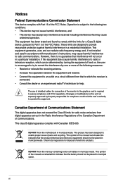
... HyperTransport™ 3.0 based system bus. Before you for the following items. Motherboard ASUS M3N78 SE motherboard Cables 1 x Serial ATA cable 1 x Serial ATA power cable 1 x Ultra DMA 133/100/66 cable Accessories 1 x I/O shield Application DVD ASUS motherboard support DVD Documentation User guide If any of ASUS quality motherboards! The motherboard delivers a host of new features and latest technologies, making it , check...
... HyperTransport™ 3.0 based system bus. Before you for the following items. Motherboard ASUS M3N78 SE motherboard Cables 1 x Serial ATA cable 1 x Serial ATA power cable 1 x Ultra DMA 133/100/66 cable Accessories 1 x I/O shield Application DVD ASUS motherboard support DVD Documentation User guide If any of ASUS quality motherboards! The motherboard delivers a host of new features and latest technologies, making it , check...
User Manual
Page 12
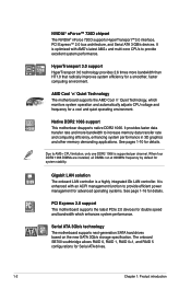
...data transfer rate and more bandwidth than HT1.0 that radically improves system efficiency for details. PCI Express 2.0 support This motherboard supports the latest PCIe 2.0 devices for a cool and quiet operating environment. Due to provide efficient power management for..., and Serial ATA 3 GB/s devices. See pages 1-10 for a smoother, faster computing environment. Serial ATA 3Gb/s technology The motherboard supports next-generation SATA hard drives based on the new SATA 3Gb/s storage specification. HyperTransport 3.0 support 5200 MT/s HyperTransport 3.0 technology ...
...data transfer rate and more bandwidth than HT1.0 that radically improves system efficiency for details. PCI Express 2.0 support This motherboard supports the latest PCIe 2.0 devices for a cool and quiet operating environment. Due to provide efficient power management for..., and Serial ATA 3 GB/s devices. See pages 1-10 for a smoother, faster computing environment. Serial ATA 3Gb/s technology The motherboard supports next-generation SATA hard drives based on the new SATA 3Gb/s storage specification. HyperTransport 3.0 support 5200 MT/s HyperTransport 3.0 technology ...
User Manual
Page 13
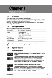
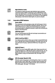
... consumers' health while minimizing the impact on the environment. See page 2-3 for details. ASUS M3N78 SE 1-3 Innovative ASUS features Green ASUS This motherboard and its packaging comply with the ASUS vision of creating environment-friendly and recyclable products/packaging to personalize your partners on the headphone... to open the case to your system. This utility saves you the cost and hassle of Hazardous Substances (RoHS). ASUS CrashFree BIOS 3 The ASUS CrashFree BIOS 3 allows you do multiple tasks, such as talking to clear CMOS data. Simply launch this tool and...
... consumers' health while minimizing the impact on the environment. See page 2-3 for details. ASUS M3N78 SE 1-3 Innovative ASUS features Green ASUS This motherboard and its packaging comply with the ASUS vision of creating environment-friendly and recyclable products/packaging to personalize your partners on the headphone... to open the case to your system. This utility saves you the cost and hassle of Hazardous Substances (RoHS). ASUS CrashFree BIOS 3 The ASUS CrashFree BIOS 3 allows you do multiple tasks, such as talking to clear CMOS data. Simply launch this tool and...
User Manual
Page 14
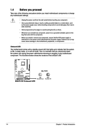
The illustration below shows the location of the following precautions before you install motherboard components or change any motherboard component. M3N78 SE SB_PWR M3N78 SE Onboard LED ON OFF Standy Power Powered Off 1-4 Chapter 1: Product introduction This is a reminder that you install or remove any component, ensure that the ATX ...
The illustration below shows the location of the following precautions before you install motherboard components or change any motherboard component. M3N78 SE SB_PWR M3N78 SE Onboard LED ON OFF Standy Power Powered Off 1-4 Chapter 1: Product introduction This is a reminder that you install or remove any component, ensure that the ATX ...
User Manual
Page 15
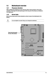
Do not overtighten the screws! Place this side towards the rear of the chassis as indicated in the image below. 1.5.2 Screw holes Place six (6) screws into the chassis in the correct orientation. M3N78 SE ASUS M3N78 SE 1-5 1.5 Motherboard overview 1.5.1 Placement direction When installing the motherboard, ensure that you place it into the holes indicated by circles to secure the motherboard to the chassis. The edge with external ports goes to the rear part of the chassis. Doing so can damage the motherboard.
Do not overtighten the screws! Place this side towards the rear of the chassis as indicated in the image below. 1.5.2 Screw holes Place six (6) screws into the chassis in the correct orientation. M3N78 SE ASUS M3N78 SE 1-5 1.5 Motherboard overview 1.5.1 Placement direction When installing the motherboard, ensure that you place it into the holes indicated by circles to secure the motherboard to the chassis. The edge with external ports goes to the rear part of the chassis. Doing so can damage the motherboard.
User Manual
Page 16
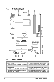
...-1 pin PRI_IDE) 1-18 14. 1.5.3 Motherboard layout 1 2 3 4 21.8cm(8.6in) KB_USB56 ATX12V CPU_FAN COM LPT SOCKET AM2 DDR2 DIMM_A1 (64bit, 240-pin module) DDR2 DIMM_B1 (64bit, 240-pin module) EATXPWR 30.5cm(12.0in) USB34 2 LAN1_USB12 AUDIO Realtek 8211CL NVIDIA® MCP78D PCIEX16 SATA4 SATA3 SATA2 SATA1 5 PCIEX1_1 M3N78 SE PCIEX1_2 USB910 USB78 USB1112...
...-1 pin PRI_IDE) 1-18 14. 1.5.3 Motherboard layout 1 2 3 4 21.8cm(8.6in) KB_USB56 ATX12V CPU_FAN COM LPT SOCKET AM2 DDR2 DIMM_A1 (64bit, 240-pin module) DDR2 DIMM_B1 (64bit, 240-pin module) EATXPWR 30.5cm(12.0in) USB34 2 LAN1_USB12 AUDIO Realtek 8211CL NVIDIA® MCP78D PCIEX16 SATA4 SATA3 SATA2 SATA1 5 PCIEX1_1 M3N78 SE PCIEX1_2 USB910 USB78 USB1112...
User Manual
Page 17
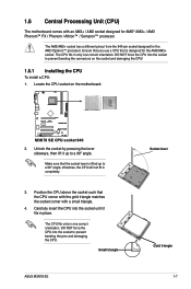
... lever is designed for the AMD Opteron™ processor. The CPU fits only in only one correct orientation. 1.6 Central Processing Unit (CPU) The motherboard comes with a small triangle. 4. Locate the CPU socket on the socket and damaging the CPU! 1.6.1 Installing the CPU To install a CPU:... for the AM2/AM2+ socket. Unlock the socket by pressing the lever sideways, then lift it fits in completely. 3. Small triangle ASUS M3N78 SE Socket lever Gold triangle 1-7 Ensure that you use a CPU that is lifted up to prevent bending the pins and damaging the CPU....
... lever is designed for the AMD Opteron™ processor. The CPU fits only in only one correct orientation. 1.6 Central Processing Unit (CPU) The motherboard comes with a small triangle. 4. Locate the CPU socket on the socket and damaging the CPU! 1.6.1 Installing the CPU To install a CPU:... for the AM2/AM2+ socket. Unlock the socket by pressing the lever sideways, then lift it fits in completely. 3. Small triangle ASUS M3N78 SE Socket lever Gold triangle 1-7 Ensure that you use a CPU that is lifted up to prevent bending the pins and damaging the CPU....
User Manual
Page 18
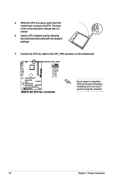
When the CPU is locked. 6. Hardware monitoring errors can occur if you fail to connect the CPU fan connector! The lever clicks on the motherboard. Install a CPU heatsink and fan following the instructions that it is in place, push down the socket lever to secure the CPU. Connect the CPU fan cable to the CPU_FAN connector on the side tab to indicate that came with the heatsink package. 7. CPU_FAN CPU FAN PWM CPU FAN IN CPU FAN PWR GND M3N78 SE M3N78 SE CPU fan connector Do not forget to plug this connector. 1-8 Chapter 1: Product introduction 5.
When the CPU is locked. 6. Hardware monitoring errors can occur if you fail to connect the CPU fan connector! The lever clicks on the motherboard. Install a CPU heatsink and fan following the instructions that it is in place, push down the socket lever to secure the CPU. Connect the CPU fan cable to the CPU_FAN connector on the side tab to indicate that came with the heatsink package. 7. CPU_FAN CPU FAN PWM CPU FAN IN CPU FAN PWR GND M3N78 SE M3N78 SE CPU fan connector Do not forget to plug this connector. 1-8 Chapter 1: Product introduction 5.
User Manual
Page 19
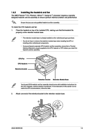
... instructions in this section do not have to remove the retention module base when installing the CPU or installing other motherboard components. • If you purchased a separate CPU heatsink and fan assembly, ensure that you install the heatsink ... 4 5 ASUS M3N78 SE 1-9 1.6.2 Installing the heatsink and fan The AMD Phenom™ FX / Phenom / Athlon™ / Sempron™ processor requires a specially designed heatsink and fan assembly to ensure optimum thermal condition and performance Ensure that a Thermal Interface Material is already installed on the motherboard upon purchase...
... instructions in this section do not have to remove the retention module base when installing the CPU or installing other motherboard components. • If you purchased a separate CPU heatsink and fan assembly, ensure that you install the heatsink ... 4 5 ASUS M3N78 SE 1-9 1.6.2 Installing the heatsink and fan The AMD Phenom™ FX / Phenom / Athlon™ / Sempron™ processor requires a specially designed heatsink and fan assembly to ensure optimum thermal condition and performance Ensure that a Thermal Interface Material is already installed on the motherboard upon purchase...
User Manual
Page 20
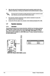
... memory 1.7.1 Overview The motherboard comes with two Double Data Rate 2 (DDR2) Dual Inline Memory Modules (DIMM) sockets. DDR2 DIMMs are notched differently to the module base. 5. Ensure that the retention bracket is in place. 4. 3. Align the other end of the DDR2 DIMM sockets: DIMM_A1 DIMM_B1 Channel Channel 1 Channel 2 M3N78 SE M3N78 SE 240-pin DDR2...
... memory 1.7.1 Overview The motherboard comes with two Double Data Rate 2 (DDR2) Dual Inline Memory Modules (DIMM) sockets. DDR2 DIMMs are notched differently to the module base. 5. Ensure that the retention bracket is in place. 4. 3. Align the other end of the DDR2 DIMM sockets: DIMM_A1 DIMM_B1 Channel Channel 1 Channel 2 M3N78 SE M3N78 SE 240-pin DDR2...
User Manual
Page 21
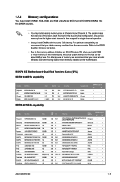
...-Sink Package GEIL • • G.SKILL F2-5400PHU2-2GBNT 2G(kit of the lower-sized channel for the OS can be about 3GB or less. M3N78 SE Motherboard Qualified Vendors Lists (QVL) DDR2-533MHz capability Vendor Part No. Any excess memory from the same vendor. Size SS/ DS CL Chip No. Kingston HY... 5 A3R12E3GEF633ACAOY PSC • • ELIXIR M2Y1G64TU8HA2B-3C 1G DS 5 M2TU51280AE-3C717095R28F ELIXIR • • Leadmax LRMP512U64A8-Y5 1G DS N/A HY5PS12821CFP-Y5 C 702AA Hynix • • ASUS M3N78 SE 1-11
...-Sink Package GEIL • • G.SKILL F2-5400PHU2-2GBNT 2G(kit of the lower-sized channel for the OS can be about 3GB or less. M3N78 SE Motherboard Qualified Vendors Lists (QVL) DDR2-533MHz capability Vendor Part No. Any excess memory from the same vendor. Size SS/ DS CL Chip No. Kingston HY... 5 A3R12E3GEF633ACAOY PSC • • ELIXIR M2Y1G64TU8HA2B-3C 1G DS 5 M2TU51280AE-3C717095R28F ELIXIR • • Leadmax LRMP512U64A8-Y5 1G DS N/A HY5PS12821CFP-Y5 C 702AA Hynix • • ASUS M3N78 SE 1-11
User Manual
Page 23
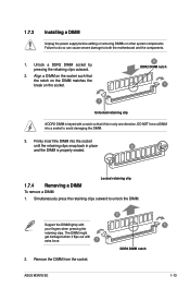
...DIMM is properly seated. Unlock a DDR2 DIMM socket by pressing the retaining clips outward. 2. Remove the DIMM from the socket. 2 DDR2 DIMM notch ASUS M3N78 SE 1 1-13 Align a DIMM on the socket such that the notch on the DIMM matches the break on the socket. 2 DDR2 DIMM notch 1 ... a notch so that it flips out with your fingers when pressing the retaining clips. Firmly insert the DIMM into a socket to both the motherboard and the components. 1. Simultaneously press the retaining clips outward to unlock the DIMM. Support the DIMM lightly with extra force. 1 2. 1.7.3 ...
...DIMM is properly seated. Unlock a DDR2 DIMM socket by pressing the retaining clips outward. 2. Remove the DIMM from the socket. 2 DDR2 DIMM notch ASUS M3N78 SE 1 1-13 Align a DIMM on the socket such that the notch on the DIMM matches the break on the socket. 2 DDR2 DIMM notch 1 ... a notch so that it flips out with your fingers when pressing the retaining clips. Firmly insert the DIMM into a socket to both the motherboard and the components. 1. Simultaneously press the retaining clips outward to unlock the DIMM. Support the DIMM lightly with extra force. 1 2. 1.7.3 ...
User Manual
Page 24
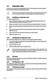
... such as a LAN card, SCSI card, USB card, and other cards that comply with PCI specifications. 1.8.4 PCI Express x1 slot This motherboard supports PCI Express x1 network cards, SCSI cards and other cards that comply with it by adjusting the software settings. 1. Replace the system cover...need IRQ assignments. Turn on the slot. 5. 1.8 Expansion slots In the future, you may cause you physical injury and damage to the motherboard components. 1.8.1 Installing an expansion card To install an expansion card: 1. Assign an IRQ to install expansion cards. Ensure that they support. ...
... such as a LAN card, SCSI card, USB card, and other cards that comply with PCI specifications. 1.8.4 PCI Express x1 slot This motherboard supports PCI Express x1 network cards, SCSI cards and other cards that comply with it by adjusting the software settings. 1. Replace the system cover...need IRQ assignments. Turn on the slot. 5. 1.8 Expansion slots In the future, you may cause you physical injury and damage to the motherboard components. 1.8.1 Installing an expansion card To install an expansion card: 1. Assign an IRQ to install expansion cards. Ensure that they support. ...
User Manual
Page 28
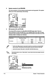
...motherboard's IDE connector, then select one of device(s) - Speaker connector (4- IDE connector (40-1 pin PRI_IDE) The onboard IDE connector is set as "Cable-Select", ensure that all other device jumpers have the same setting. If any device jumper is for Ultra DMA 133/100/66 signal cable. M3N78 SE PRI_IDE M3N78 SE... 2. pin SPEAKER) This 4-pin connector is removed to hear system beeps and warnings. +5V GND GND Speaker Out M3N78 SE SPEAKER PIN 1 M3N78 SE Speaker Out Connector 3. The speaker allows you connect the IDE cable. • Use the 80-conductor IDE cable for...
...motherboard's IDE connector, then select one of device(s) - Speaker connector (4- IDE connector (40-1 pin PRI_IDE) The onboard IDE connector is set as "Cable-Select", ensure that all other device jumpers have the same setting. If any device jumper is for Ultra DMA 133/100/66 signal cable. M3N78 SE PRI_IDE M3N78 SE... 2. pin SPEAKER) This 4-pin connector is removed to hear system beeps and warnings. +5V GND GND Speaker Out M3N78 SE SPEAKER PIN 1 M3N78 SE Speaker Out Connector 3. The speaker allows you connect the IDE cable. • Use the 80-conductor IDE cable for...
User Manual
Page 30
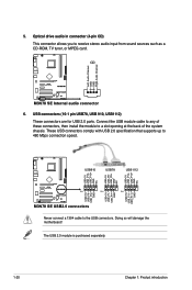
... 1 PIN 1 PIN 1 USB+5V USB_P9USB_P9+ GND USB+5V USB_P7USB_P7+ GND USB+5V USB_P11USB_P11+ GND M3N78 SE USB2.0 connectors Never connect a 1394 cable to 480 Mbps connection speed. Doing so will damage the motherboard! The USB 2.0 module is purchased separately. 1-20 Chapter 1: Product introduction USB connectors (10-1 pin USB78, USB 910, USB1112) These connectors... of these connectors, then install the module to receive stereo audio input from sound sources such as a CD-ROM, TV tuner, or MPEG card. CD M3N78 SE M3N78 SE Internal audio connector 6.
... 1 PIN 1 PIN 1 USB+5V USB_P9USB_P9+ GND USB+5V USB_P7USB_P7+ GND USB+5V USB_P11USB_P11+ GND M3N78 SE USB2.0 connectors Never connect a 1394 cable to 480 Mbps connection speed. Doing so will damage the motherboard! The USB 2.0 module is purchased separately. 1-20 Chapter 1: Product introduction USB connectors (10-1 pin USB78, USB 910, USB1112) These connectors... of these connectors, then install the module to receive stereo audio input from sound sources such as a CD-ROM, TV tuner, or MPEG card. CD M3N78 SE M3N78 SE Internal audio connector 6.


