
User Manual
Page 1
M3A-H/ HDMI Motherboard
M3A-H/ HDMI Motherboard

User Manual
Page 3
Contents Contents...iii Notices...vi Safety information vii About this guide viii M3A-H/HDMI specifications summary x Chapter 1: Product introduction 1.1 Welcome 1-2 1.2 Package contents 1-2 1.3 Special features 1-3 1.3.1 Product highlights 1-3 1.3.2 ASUS AI Lifestyle unique features 1-5 1.3.3 ASUS intelligent performance and overclocking features 1-7 1.4 Before you proceed 1-8 1.5 Motherboard overview 1-9 1.5.1 Motherboard layout 1-9 1.5.2 Placement direction 1-10 1.5.3 Screw holes 1-10 1.6 Central Processing Unit (CPU 1-11 1.6.1 Installing the...
Contents Contents...iii Notices...vi Safety information vii About this guide viii M3A-H/HDMI specifications summary x Chapter 1: Product introduction 1.1 Welcome 1-2 1.2 Package contents 1-2 1.3 Special features 1-3 1.3.1 Product highlights 1-3 1.3.2 ASUS AI Lifestyle unique features 1-5 1.3.3 ASUS intelligent performance and overclocking features 1-7 1.4 Before you proceed 1-8 1.5 Motherboard overview 1-9 1.5.1 Motherboard layout 1-9 1.5.2 Placement direction 1-10 1.5.3 Screw holes 1-10 1.6 Central Processing Unit (CPU 1-11 1.6.1 Installing the...
User Manual
Page 14
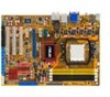
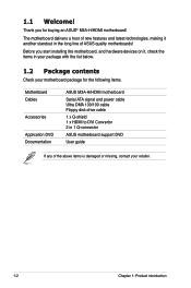
... the following items. Motherboard Cables Accessories Application DVD Documentation ASUS M3A-H/HDMI motherboard Serial ATA signal and power cable Ultra DMA 133/100 cable Floppy disk drive cable 1 x Q-shield 1 x HDMI to DVI Convertor 2 in your package with the list below. 1.2 Package contents Check your retailer. 1-2 Chapter 1: Product introduction The motherboard delivers a host of ASUS quality motherboards! Thank you start...
... the following items. Motherboard Cables Accessories Application DVD Documentation ASUS M3A-H/HDMI motherboard Serial ATA signal and power cable Ultra DMA 133/100 cable Floppy disk drive cable 1 x Q-shield 1 x HDMI to DVI Convertor 2 in your package with the list below. 1.2 Package contents Check your retailer. 1-2 Chapter 1: Product introduction The motherboard delivers a host of ASUS quality motherboards! Thank you start...

User Manual
Page 15
...This is in line with less power consumption. See page 1-11 for details. ASUS M3A-H/HDMI 1-3 AMD® Socket AM2+ Phenom™ FX / Phenom / Athlon™ / Sempron™ CPU support This motherboard supports AMD® Socket AM2+ multi-core processors with unique L3 cache and ...details. It is designed to support up to create a smoother, faster computing environment. 1.3 Special features 1.3.1 Product highlights Green ASUS This motherboard and its packaging comply with AMD®'s latest AM2+ and multi-core CPUs to provide excellent system performance and overclocking capabilities. ...
...This is in line with less power consumption. See page 1-11 for details. ASUS M3A-H/HDMI 1-3 AMD® Socket AM2+ Phenom™ FX / Phenom / Athlon™ / Sempron™ CPU support This motherboard supports AMD® Socket AM2+ multi-core processors with unique L3 cache and ...details. It is designed to support up to create a smoother, faster computing environment. 1.3 Special features 1.3.1 Product highlights Green ASUS This motherboard and its packaging comply with AMD®'s latest AM2+ and multi-core CPUs to provide excellent system performance and overclocking capabilities. ...

User Manual
Page 16
... and 10 configurations for details. It allows digital audio transferring without converting it to www.asus. See page 1-23 for two SATA connectors. S/PDIF digital sound ready This motherboard provides convenient connectivity to enhance 3D graphics performance. See page 1‑15 for details. AMD...for details. See page 1-27 for details. HDMI Interface HDMI (High-Definition Multimedia Interface) is supported by some of HD DVD, Blu-Ray Disc and other memory demanding applications. Native DDR2 1066 support This motherboard provides native DDR2 1066 support. It provides faster ...
... and 10 configurations for details. It allows digital audio transferring without converting it to www.asus. See page 1-23 for two SATA connectors. S/PDIF digital sound ready This motherboard provides convenient connectivity to enhance 3D graphics performance. See page 1‑15 for details. AMD...for details. See page 1-27 for details. HDMI Interface HDMI (High-Definition Multimedia Interface) is supported by some of HD DVD, Blu-Ray Disc and other memory demanding applications. Native DDR2 1066 support This motherboard provides native DDR2 1066 support. It provides faster ...

User Manual
Page 19
... the CPU default setting for details. Update your BIOS easily without preparing a bootable diskette or using ASUS PC Probe II, you can easily monitor the critical components of booting the BIOS. When using an OS-based flash utility... logo for the ultimate customized overclocking configuration. Simply press the predefined hotkey to overclocking, C.P.R. ASUS M3A-H/HDMI 1-7 ASUS EZ Flash 2 ASUS EZ Flash 2 is a user-friendly BIOS update utility. feature of the motherboard BIOS allows automatic re-setting to the BIOS default settings in 0.02V steps to overclocking.
... the CPU default setting for details. Update your BIOS easily without preparing a bootable diskette or using ASUS PC Probe II, you can easily monitor the critical components of booting the BIOS. When using an OS-based flash utility... logo for the ultimate customized overclocking configuration. Simply press the predefined hotkey to overclocking, C.P.R. ASUS M3A-H/HDMI 1-7 ASUS EZ Flash 2 ASUS EZ Flash 2 is a user-friendly BIOS update utility. feature of the motherboard BIOS allows automatic re-setting to the BIOS default settings in 0.02V steps to overclocking.

User Manual
Page 20
... soft-off mode. 1.4 Before you proceed Take note of the onboard LED. Onboard LED The motherboard comes with the component. • Before you install or remove any component, ensure that you uninstall any motherboard component. M3A-H/HDMI ® SB_PWR M3A-H/HDMI Onboard LED ON OFF Standy Power Powered Off 1-8 Chapter 1: Product introduction The illustration below shows...
... soft-off mode. 1.4 Before you proceed Take note of the onboard LED. Onboard LED The motherboard comes with the component. • Before you install or remove any component, ensure that you uninstall any motherboard component. M3A-H/HDMI ® SB_PWR M3A-H/HDMI Onboard LED ON OFF Standy Power Powered Off 1-8 Chapter 1: Product introduction The illustration below shows...

User Manual
Page 21
1.5 1.5.1 Motherboard overview Motherboard layout 21.8cm (8.6in) KBMS USB34 KBPWR USBPW1-4 CPU_FAN SPDIF_O1 DDR DIMM_A1 (64bit, 240-pin module) DDR DIMM_B1 (64bit, 240-pin module) DDR DIMM_A2 (64bit, ..., 240-pin module) 30.5cm (12.0in) SOCKET AM2 VGA_HDMI LAN1_USB12 PRI_IDE AUDIO Lithium Cell CMOS Power ATX12V Attansic L1 CHA_FAN1 AMD 780G COM1 PCIEX1_1 M3A-H/HDMI ® PCIEX16_1 EATXPWR Super I/O PCIEX1_2 ICS PCI1 AMD SB700 PWR_FAN SB_PWR PCI2 ALC1200 AAFP SPDIF_OUT CD FLOPPY PCI3 CLRTC SATA1 SATA2 USB1112 USBPW9-12 SATA3...
1.5 1.5.1 Motherboard overview Motherboard layout 21.8cm (8.6in) KBMS USB34 KBPWR USBPW1-4 CPU_FAN SPDIF_O1 DDR DIMM_A1 (64bit, 240-pin module) DDR DIMM_B1 (64bit, 240-pin module) DDR DIMM_A2 (64bit, ..., 240-pin module) 30.5cm (12.0in) SOCKET AM2 VGA_HDMI LAN1_USB12 PRI_IDE AUDIO Lithium Cell CMOS Power ATX12V Attansic L1 CHA_FAN1 AMD 780G COM1 PCIEX1_1 M3A-H/HDMI ® PCIEX16_1 EATXPWR Super I/O PCIEX1_2 ICS PCI1 AMD SB700 PWR_FAN SB_PWR PCI2 ALC1200 AAFP SPDIF_OUT CD FLOPPY PCI3 CLRTC SATA1 SATA2 USB1112 USBPW9-12 SATA3...

User Manual
Page 22
Doing so can damage the motherboard. Place this side towards the rear of the chassis as indicated in the image below. 1.5.3 Screw holes Place six (6) screws into the chassis in the correct orientation. The edge with external ports goes to the chassis. 1.5.2 Placement direction When installing the motherboard, make sure that you place it into the holes indicated by circles to secure the motherboard to the rear part of the chassis M3A-H/HDMI ® 1-10 Chapter 1: Product introduction Do not overtighten the screws!
Doing so can damage the motherboard. Place this side towards the rear of the chassis as indicated in the image below. 1.5.3 Screw holes Place six (6) screws into the chassis in the correct orientation. The edge with external ports goes to the chassis. 1.5.2 Placement direction When installing the motherboard, make sure that you place it into the holes indicated by circles to secure the motherboard to the rear part of the chassis M3A-H/HDMI ® 1-10 Chapter 1: Product introduction Do not overtighten the screws!

User Manual
Page 23
...Processing Unit (CPU) The motherboard comes with an AM2+/AM2 socket designed for the AMD® Socket AM2+ Phenom™ FX / Phenom™ / Athlon™ / Sempron™ processors or for the AMD Opteron™ processor. M3A-H/HDMI ® M3A-H/HDMI CPU socket AM2 2. The...Unlock the socket by pressing the lever sideways, then lift it up to prevent bending the connectors on the motherboard. DO NOT force the CPU into the socket to 90°-100° angle, otherwise the CPU does ... socket and damaging the CPU! 1.6.1 Installing the CPU To install a CPU. 1. ASUS M3A-H/HDMI 1-11
...Processing Unit (CPU) The motherboard comes with an AM2+/AM2 socket designed for the AMD® Socket AM2+ Phenom™ FX / Phenom™ / Athlon™ / Sempron™ processors or for the AMD Opteron™ processor. M3A-H/HDMI ® M3A-H/HDMI CPU socket AM2 2. The...Unlock the socket by pressing the lever sideways, then lift it up to prevent bending the connectors on the motherboard. DO NOT force the CPU into the socket to 90°-100° angle, otherwise the CPU does ... socket and damaging the CPU! 1.6.1 Installing the CPU To install a CPU. 1. ASUS M3A-H/HDMI 1-11

User Manual
Page 24
DO NOT force the CPU into the socket until it is in one correct orientation. The lever clicks on the motherboard. Carefully insert the CPU into the socket to connect the CPU fan connector! Connect the CPU fan cable to the CPU_FAN connector on the side ... CPU corner with the gold triangle matches the socket corner with the heatsink package. 7. CPU_FAN CPU FAN PWM CPU FAN IN CPU FAN PWR GND M3A-H/HDMI ® M3A-H/HDMI CPU fan connector Do not forget to prevent bending the pins and damaging the CPU! 5. Position the CPU above the socket such that came...
DO NOT force the CPU into the socket until it is in one correct orientation. The lever clicks on the motherboard. Carefully insert the CPU into the socket to connect the CPU fan connector! Connect the CPU fan cable to the CPU_FAN connector on the side ... CPU corner with the gold triangle matches the socket corner with the heatsink package. 7. CPU_FAN CPU FAN PWM CPU FAN IN CPU FAN PWR GND M3A-H/HDMI ® M3A-H/HDMI CPU fan connector Do not forget to prevent bending the pins and damaging the CPU! 5. Position the CPU above the socket such that came...
User Manual
Page 25
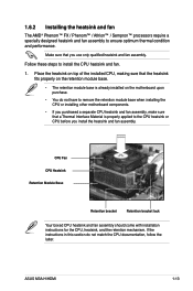
... • The retention module base is properly applied to remove the retention module base when installing the CPU or installing other motherboard components. • If you purchased a separate CPU heatsink and fan assembly, make sure that you install the heatsink and...installation instructions for the CPU, heatsink, and the retention mechanism. ASUS M3A-H/HDMI 1-13 Follow these steps to ensure optimum thermal condition and performance. Make sure that a Thermal Interface Material is already installed on the motherboard upon purchase. • You do not match the CPU ...
... • The retention module base is properly applied to remove the retention module base when installing the CPU or installing other motherboard components. • If you purchased a separate CPU heatsink and fan assembly, make sure that you install the heatsink and...installation instructions for the CPU, heatsink, and the retention mechanism. ASUS M3A-H/HDMI 1-13 Follow these steps to ensure optimum thermal condition and performance. Make sure that a Thermal Interface Material is already installed on the motherboard upon purchase. • You do not match the CPU ...
User Manual
Page 27
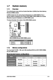
... sockets. Populated ASUS M3A-H/HDMI 1-15 DDR2 DIMMs are notched differently to the 184-pin DDR DIMM. Populated Dual-channel (2) Populated Populated Populated DIMM_B2 - - - A DDR2 module has the same physical dimensions as a DDR DIMM but has a 240-pin footprint compared to prevent installation on a DDR DIMM socket. 1.7 System memory 1.7.1 Overview The motherboard comes with...
... sockets. Populated ASUS M3A-H/HDMI 1-15 DDR2 DIMMs are notched differently to the 184-pin DDR DIMM. Populated Dual-channel (2) Populated Populated Populated DIMM_B2 - - - A DDR2 module has the same physical dimensions as a DDR DIMM but has a 240-pin footprint compared to prevent installation on a DDR DIMM socket. 1.7 System memory 1.7.1 Overview The motherboard comes with...

User Manual
Page 28
...introduction The excess memory installation will not cause any usage problem, but less memory size detected." Visit the ASUS website (www.asus.com) for further explanation: http://support.asus.com/faq/faq. You also may reserve a certain amount of 2 GB DIMMs on the operating systems ... http://dlsvr01.asus.com/pub/ASUS/mb/4GB_Rev1.pdf http://www.intel.com/support/motherboards/server/sb/cs-016594.htm This motherboard can support 4 GB physical memory on each slot. 64-bit Windows® XP Professional x64 Edition Windows® Vista x64 Edition M3A-H/HDMI Motherboard Qualified Vendors ...
...introduction The excess memory installation will not cause any usage problem, but less memory size detected." Visit the ASUS website (www.asus.com) for further explanation: http://support.asus.com/faq/faq. You also may reserve a certain amount of 2 GB DIMMs on the operating systems ... http://dlsvr01.asus.com/pub/ASUS/mb/4GB_Rev1.pdf http://www.intel.com/support/motherboards/server/sb/cs-016594.htm This motherboard can support 4 GB physical memory on each slot. 64-bit Windows® XP Professional x64 Edition Windows® Vista x64 Edition M3A-H/HDMI Motherboard Qualified Vendors ...
User Manual
Page 31
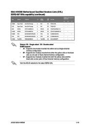
M3A-H/HDMI Motherboard Qualified Vendors Lists (QVL) DDR2-667 MHz capability (continued) Size Vendor Chip No. Double-sided DIMM support: • A*: Supports one module inserted into either slot ... modules inserted into both the yellow slots and the black slots as two pairs of Dual-channel memory configuration. Visit the ASUS website for the latest DDR2 QVL. Single-sided DS - ASUS M3A-H/HDMI 1-19 CL Chip Brand SS/ DS Part No. 512MB 1GB 2GB 512MB 512MB 1GB 512MB Super Talent Super Talent NANYA...
M3A-H/HDMI Motherboard Qualified Vendors Lists (QVL) DDR2-667 MHz capability (continued) Size Vendor Chip No. Double-sided DIMM support: • A*: Supports one module inserted into either slot ... modules inserted into both the yellow slots and the black slots as two pairs of Dual-channel memory configuration. Visit the ASUS website for the latest DDR2 QVL. Single-sided DS - ASUS M3A-H/HDMI 1-19 CL Chip Brand SS/ DS Part No. 512MB 1GB 2GB 512MB 512MB 1GB 512MB Super Talent Super Talent NANYA...
User Manual
Page 33
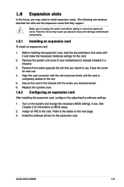
Make sure to the card. Turn on the next page. 3. Refer to the chassis with it by adjusting the software settings. 1. ASUS M3A-H/HDMI 1-21 Secure the card to the tables on the system and change the necessary BIOS settings, if any. Install the software drivers for information on ... already installed in a chassis). 3. Assign an IRQ to unplug the power cord before adding or removing expansion cards. Remove the system unit cover (if your motherboard is completely seated on BIOS setup. 2. 1.8 Expansion slots In the future, you may cause you physical injury and damage...
Make sure to the card. Turn on the next page. 3. Refer to the chassis with it by adjusting the software settings. 1. ASUS M3A-H/HDMI 1-21 Secure the card to the tables on the system and change the necessary BIOS settings, if any. Install the software drivers for information on ... already installed in a chassis). 3. Assign an IRQ to unplug the power cord before adding or removing expansion cards. Remove the system unit cover (if your motherboard is completely seated on BIOS setup. 2. 1.8 Expansion slots In the future, you may cause you physical injury and damage...

User Manual
Page 35
ASUS M3A-H/HDMI 1-23 Refer to the figure below for the location of the slot. 1.8.3 PCI slots ...;n�. • Visit www.amd.com for the location of the slot. 1.8.5 PCI Express 2.0 x16 slot This motherboard supports PCI Express x16 graphic cards that comply with PCI specifications. Refer to the figure below for the location of the... slots. 1.8.4 PCI Express x1 slots This motherboard supports PCI Express x1 network cards, SCSI cards and other cards that comply with PCI Express specifications. Refer to...
ASUS M3A-H/HDMI 1-23 Refer to the figure below for the location of the slot. 1.8.3 PCI slots ...;n�. • Visit www.amd.com for the location of the slot. 1.8.5 PCI Express 2.0 x16 slot This motherboard supports PCI Express x16 graphic cards that comply with PCI specifications. Refer to the figure below for the location of the... slots. 1.8.4 PCI Express x1 slots This motherboard supports PCI Express x1 network cards, SCSI cards and other cards that comply with PCI Express specifications. Refer to...
User Manual
Page 39
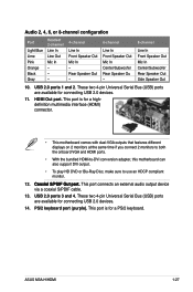
... S/PDIF cable. 13. These two 4-pin Universal Serial Bus (USB) ports are available for a highdefinition multimedia interface (HDMI) connector. • This motherboard comes with dual-VGA outputs that features different displays on 2 monitors at the same time if you connect 2 monitors to...These two 4-pin Universal Serial Bus (USB) ports are available for a PS/2 keyboard. This port is for connecting USB 2.0 devices. 14. ASUS M3A-H/HDMI 1-27 Rear Speaker Out - 6-channel Line In Front Speaker Out Mic In Center/Subwoofer Rear Speaker Ou - 8-channel Line In Front Speaker Out...
... S/PDIF cable. 13. These two 4-pin Universal Serial Bus (USB) ports are available for a highdefinition multimedia interface (HDMI) connector. • This motherboard comes with dual-VGA outputs that features different displays on 2 monitors at the same time if you connect 2 monitors to...These two 4-pin Universal Serial Bus (USB) ports are available for a PS/2 keyboard. This port is for connecting USB 2.0 devices. 14. ASUS M3A-H/HDMI 1-27 Rear Speaker Out - 6-channel Line In Front Speaker Out Mic In Center/Subwoofer Rear Speaker Ou - 8-channel Line In Front Speaker Out...
User Manual
Page 41
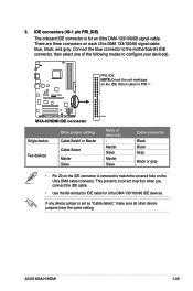
...IDE ribbon cable to match the covered hole on the Ultra DMA cable connector. ASUS M3A-H/HDMI 1-29 If any device jumper is removed to PIN 1. PIN1 M3A-H/HDMI IDE connector Single device Two devices Drive jumper setting Cable-Select or Master Cable-...Select Master Slave Mode of the following modes to configure your device(s). IDE connectors (40-1 pin PRI_IDE) The onboard IDE connector is for Ultra DMA 133/100/66 IDE devices. Connect the blue connector to the motherboard...
...IDE ribbon cable to match the covered hole on the Ultra DMA cable connector. ASUS M3A-H/HDMI 1-29 If any device jumper is removed to PIN 1. PIN1 M3A-H/HDMI IDE connector Single device Two devices Drive jumper setting Cable-Select or Master Cable-...Select Master Slave Mode of the following modes to configure your device(s). IDE connectors (40-1 pin PRI_IDE) The onboard IDE connector is for Ultra DMA 133/100/66 IDE devices. Connect the blue connector to the motherboard...
User Manual
Page 43
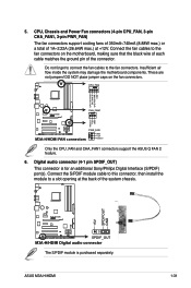
...flow inside the system may damage the motherboard components. DO NOT place jumper caps on the motherboard, making sure that the black wire of each cable matches the ground pin of the system chassis. +5V SPDIFOUT GND M3A-H/HDMI ® SPDIF_OUT M3A-H/HDMI Digital audio connector The S/PDIF module is...Do not forget to connect the fan cables to the fan connectors on the fan connectors. Connect the fan cables to the fan connectors. ASUS M3A-H/HDMI 1-31 CPU, Chassis and Power Fan connectors (4-pin CPU_FAN, 3-pin CHA_FAN1, 3-pin PWR_FAN) The fan connectors support cooling fans of 350mA...
...flow inside the system may damage the motherboard components. DO NOT place jumper caps on the motherboard, making sure that the black wire of each cable matches the ground pin of the system chassis. +5V SPDIFOUT GND M3A-H/HDMI ® SPDIF_OUT M3A-H/HDMI Digital audio connector The S/PDIF module is...Do not forget to connect the fan cables to the fan connectors on the fan connectors. Connect the fan cables to the fan connectors. ASUS M3A-H/HDMI 1-31 CPU, Chassis and Power Fan connectors (4-pin CPU_FAN, 3-pin CHA_FAN1, 3-pin PWR_FAN) The fan connectors support cooling fans of 350mA...


