User Manual
Page 9
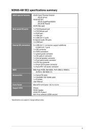
... Form Factor Support DVD ASUS Quiet Thermal Solution - ASUS CrashFree BIOS3 - M2N68-AM SE2 specifications summary ASUS special features Back panel ...I/O ports Internal I /O ports 1 x COM port 3 x USB 2.0/1.1 connectors support additional 6 USB 2.0/1.1 ports 1 x IDE connector 2 x SATA connectors 1 x system panel connector 1 x CD audio-in connector 1 x Internal speaker connector 1 x Front panel audio connector 1 x CPU fan connector 1 x 24-pin EATX power connector 1 x 4-pin ATX...
... Form Factor Support DVD ASUS Quiet Thermal Solution - ASUS CrashFree BIOS3 - M2N68-AM SE2 specifications summary ASUS special features Back panel ...I/O ports Internal I /O ports 1 x COM port 3 x USB 2.0/1.1 connectors support additional 6 USB 2.0/1.1 ports 1 x IDE connector 2 x SATA connectors 1 x system panel connector 1 x CD audio-in connector 1 x Internal speaker connector 1 x Front panel audio connector 1 x CPU fan connector 1 x 24-pin EATX power connector 1 x 4-pin ATX...
User Manual
Page 11
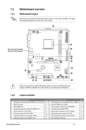
Place this side towards the rear of the chassis. ATX power connectors (24-pin EATXPWR, 4-pin ATX12V) 2. AM2 CPU Socket 3. Keyboard/mouse power (3-pin PS2_USBPW 1-4) 5. Doing so can damage the motherboard. 1.2.2 Layout contents Connectors/Jumpers/Slots/LED 1. Standby ...fan connector (4-pin CPU_FAN) 7. Clear RTC RAM (3-pin CLRTC) 11. System panel connector (10-1 pin F_PANEL) 14. PCIe x16/PCIe x1/PCI slots Page 1-12 1-7 1-13 1-1 1-14 1-11 1-14 1-7 ASUS M2N68-AM SE2 1-2 1.2 1.2.1 Motherboard overview Motherboard layout Ensure that you install the motherboard...
Place this side towards the rear of the chassis. ATX power connectors (24-pin EATXPWR, 4-pin ATX12V) 2. AM2 CPU Socket 3. Keyboard/mouse power (3-pin PS2_USBPW 1-4) 5. Doing so can damage the motherboard. 1.2.2 Layout contents Connectors/Jumpers/Slots/LED 1. Standby ...fan connector (4-pin CPU_FAN) 7. Clear RTC RAM (3-pin CLRTC) 11. System panel connector (10-1 pin F_PANEL) 14. PCIe x16/PCIe x1/PCI slots Page 1-12 1-7 1-13 1-1 1-14 1-11 1-14 1-7 ASUS M2N68-AM SE2 1-2 1.2 1.2.1 Motherboard overview Motherboard layout Ensure that you install the motherboard...
User Manual
Page 21
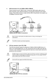
...fan supports the ASUS Q-Fan feature. Never connect a 1394 cable to the CPU fan connector. 4. USB connectors (10-1 pin USB56, USB78, USB910) These connectors are for USB 2.0 ports. DO NOT place a jumper cap on the motherboard, ensuring that supports up to a slot opening at the back of 1A~2.22A (26.64W max.) at +12V. ASUS M2N68-AM SE2... 1-12 These USB connectors comply with the USB 2.0 specification that the black wire of each cable matches the ground pin of the connector. Insufficient air flow inside the system may damage the motherboard components. The...
...fan supports the ASUS Q-Fan feature. Never connect a 1394 cable to the CPU fan connector. 4. USB connectors (10-1 pin USB56, USB78, USB910) These connectors are for USB 2.0 ports. DO NOT place a jumper cap on the motherboard, ensuring that supports up to a slot opening at the back of 1A~2.22A (26.64W max.) at +12V. ASUS M2N68-AM SE2... 1-12 These USB connectors comply with the USB 2.0 specification that the black wire of each cable matches the ground pin of the connector. Insufficient air flow inside the system may damage the motherboard components. The...


