
User Manual
Page 1
Motherboard
Motherboard

User Manual
Page 1
M2N68-AM SE Motherboard
M2N68-AM SE Motherboard
User Manual
Page 3
Contents Notices...v Safety information vi About this guide vi M2N68-AM SE specifications summary viii Chapter 1: Product introduction 1.1 Before you proceed 1-1 1.2 Motherboard overview 1-2 1.2.1 Motherboard layout 1-2 1.2.2 Layout contents 1-2 1.3 Central Processing Unit (CPU 1-3 1.4 System memory 1-3 1.4.1 Overview 1-3 1.4.2 Memory configurations 1-4 1.5 Expansion... connectors 1-10 1.8 Software support 1-15 1.8.1 Installing an operating system 1-15 1.8.2 Support DVD information 1-15 1.8.3 ASUS Express Gate 1-16 Chapter 2: BIOS information 2.1 Managing and updating your BIOS...
Contents Notices...v Safety information vi About this guide vi M2N68-AM SE specifications summary viii Chapter 1: Product introduction 1.1 Before you proceed 1-1 1.2 Motherboard overview 1-2 1.2.1 Motherboard layout 1-2 1.2.2 Layout contents 1-2 1.3 Central Processing Unit (CPU 1-3 1.4 System memory 1-3 1.4.1 Overview 1-3 1.4.2 Memory configurations 1-4 1.5 Expansion... connectors 1-10 1.8 Software support 1-15 1.8.1 Installing an operating system 1-15 1.8.2 Support DVD information 1-15 1.8.3 ASUS Express Gate 1-16 Chapter 2: BIOS information 2.1 Managing and updating your BIOS...

User Manual
Page 5
... crossed out wheeled bin indicates that the battery should not be placed in accordance with manufacturer's instructions, may cause undesired operation. DO NOT throw the motherboard in a residential installation. The use of shielded cables for compliance could void the user's authority to operate this equipment does cause harmful interference to assure...
... crossed out wheeled bin indicates that the battery should not be placed in accordance with manufacturer's instructions, may cause undesired operation. DO NOT throw the motherboard in a residential installation. The use of shielded cables for compliance could void the user's authority to operate this equipment does cause harmful interference to assure...
User Manual
Page 6
...this guide is organized This guide contains the following parts: • Chapter 1: Product introduction This chapter describes the features of the motherboard and the new technology it supports. • Chapter 2: BIOS information This chapter tells how to change system settings through the BIOS... menus. If possible, disconnect all cables are correctly connected and the power cables are connected. Operation safety • Before installing the motherboard and adding devices on a flat and stable surface. • If you encounter technical problems with the package. • Before using...
...this guide is organized This guide contains the following parts: • Chapter 1: Product introduction This chapter describes the features of the motherboard and the new technology it supports. • Chapter 2: BIOS information This chapter tells how to change system settings through the BIOS... menus. If possible, disconnect all cables are correctly connected and the power cables are connected. Operation safety • Before installing the motherboard and adding devices on a flat and stable surface. • If you encounter technical problems with the package. • Before using...
User Manual
Page 10
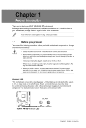
... following precautions before removing or plugging in the bag that came with a standby power LED that lights up to page ix for buying an ASUS® M2N68-AM SE motherboard! Chapter 1 Product introduction Thank you for the list of accessories. This is a reminder that you uninstall any of the onboard LED. The illustration below...
... following precautions before removing or plugging in the bag that came with a standby power LED that lights up to page ix for buying an ASUS® M2N68-AM SE motherboard! Chapter 1 Product introduction Thank you for the list of accessories. This is a reminder that you uninstall any of the onboard LED. The illustration below...
User Manual
Page 11
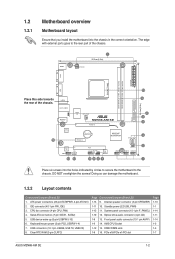
... the holes indicated by circles to secure the motherboard to the rear part of the chassis. 16 15 USB34 24.4cm(9.6in) LAN1_USB12 AUDIO RTL 8201CP USBPW1-4 Super I/O CPU_FAN M2N68-AM SE PCIEX16 Lithium Cell CMOS Power PCIEX1_1 NVIDIA® MCP68PVNT ...motherboard. 1.2.2 Layout contents Connectors/Jumpers/Slots/LED 1. Clear RTC RAM (3-pin CLRTC) Page Connectors/Jumpers/Slots/LED 1-13 9. Internal speaker connector (4-pin SPEAKER) 1-11 10. Front panel audio connector (10-1 pin AAFP) 1-9 14. PCIe x16/PCIe x1/PCI slot Page 1-13 1-1 1-14 1-11 1-14 1-3 1-3 1-7 ASUS M2N68-AM SE...
... the holes indicated by circles to secure the motherboard to the rear part of the chassis. 16 15 USB34 24.4cm(9.6in) LAN1_USB12 AUDIO RTL 8201CP USBPW1-4 Super I/O CPU_FAN M2N68-AM SE PCIEX16 Lithium Cell CMOS Power PCIEX1_1 NVIDIA® MCP68PVNT ...motherboard. 1.2.2 Layout contents Connectors/Jumpers/Slots/LED 1. Clear RTC RAM (3-pin CLRTC) Page Connectors/Jumpers/Slots/LED 1-13 9. Internal speaker connector (4-pin SPEAKER) 1-11 10. Front panel audio connector (10-1 pin AAFP) 1-9 14. PCIe x16/PCIe x1/PCI slot Page 1-13 1-1 1-14 1-11 1-14 1-3 1-3 1-7 ASUS M2N68-AM SE...

User Manual
Page 12
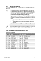
...-pin DDR DIMM. The figure illustrates the location of the DDR2 DIMM sockets: DIMM_A1 DIMM_B1 M2N68-AM SE M2N68-AM SE 240-pin DDR2 DIMM sockets Channel Channel A Channel B Sockets DIMM_A1 DIMM_B1 1-3 Chapter 1: Product introduction 1.3 Central Processing Unit (CPU) This motherboard comes with two Double Data Rate 2 (DDR2) Dual Inline Memory Modules (DIMM) sockets. Use...
...-pin DDR DIMM. The figure illustrates the location of the DDR2 DIMM sockets: DIMM_A1 DIMM_B1 M2N68-AM SE M2N68-AM SE 240-pin DDR2 DIMM sockets Channel Channel A Channel B Sockets DIMM_A1 DIMM_B1 1-3 Chapter 1: Product introduction 1.3 Central Processing Unit (CPU) This motherboard comes with two Double Data Rate 2 (DDR2) Dual Inline Memory Modules (DIMM) sockets. Use...
User Manual
Page 13
...8226; • • • • • • • • • • • • • • • • • • ASUS M2N68-AM SE 1-4 Install a maximum of 2GB DIMMs on each slot. You may install varying memory sizes in Channel A and Channel B. Any excess memory from the same vendor...DIMMs made up to install 4GB or more memory on Windows XP Professional x64 and Vista x64 editions. This motherboard supports up of the lower-sized channel for the dual-channel configuration. 1.4.2 Memory configurations You may install 256MB...
...8226; • • • • • • • • • • • • • • • • • • ASUS M2N68-AM SE 1-4 Install a maximum of 2GB DIMMs on each slot. You may install varying memory sizes in Channel A and Channel B. Any excess memory from the same vendor...DIMMs made up to install 4GB or more memory on Windows XP Professional x64 and Vista x64 editions. This motherboard supports up of the lower-sized channel for the dual-channel configuration. 1.4.2 Memory configurations You may install 256MB...
User Manual
Page 16
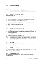
...future, you may cause you intend to install expansion cards. Remove the bracket opposite the slot that you physical injury and damage motherboard components. 1.5.1 Installing an expansion card To install an expansion card: 1. Before installing the expansion card, read the documentation that comply with... any. Align the card connector with the screw. 6. When using PCI cards on the slot. 5. Remove the chassis cover (if your motherboard is completely seated on shared slots, ensure that the drivers support "Share IRQ" or that they support. Secure the card to the card....
...future, you may cause you intend to install expansion cards. Remove the bracket opposite the slot that you physical injury and damage motherboard components. 1.5.1 Installing an expansion card To install an expansion card: 1. Before installing the expansion card, read the documentation that comply with... any. Align the card connector with the screw. 6. When using PCI cards on the slot. 5. Remove the chassis cover (if your motherboard is completely seated on shared slots, ensure that the drivers support "Share IRQ" or that they support. Secure the card to the card....
User Manual
Page 20
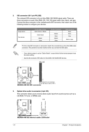
.... IDE connector (40-1 pin PRI_IDE) The onboard IDE connector is removed to configure your devices. Connect the blue connector to the motherboard's IDE connector, then select one of device(s) - Master Slave Master Slave Cable connector Black Black Gray Black or gray Pin 20 ...100 / 66 signal cable: blue, black, and gray. CD Right Audio Channel Left Audio Channel GND GND M2N68-AM SE M2N68-AM SE Internal audio connector 1-11 Chapter 1: Product introduction M2N68-AM SE IDE connector 3. There are three connectors on the IDE connector is for Ultra DMA 133/100/66 IDE devices...
.... IDE connector (40-1 pin PRI_IDE) The onboard IDE connector is removed to configure your devices. Connect the blue connector to the motherboard's IDE connector, then select one of device(s) - Master Slave Master Slave Cable connector Black Black Gray Black or gray Pin 20 ...100 / 66 signal cable: blue, black, and gray. CD Right Audio Channel Left Audio Channel GND GND M2N68-AM SE M2N68-AM SE Internal audio connector 1-11 Chapter 1: Product introduction M2N68-AM SE IDE connector 3. There are three connectors on the IDE connector is for Ultra DMA 133/100/66 IDE devices...

User Manual
Page 21
...for USB 2.0 ports. Doing so will damage the motherboard! Connect the CPU fan cable to the USB connectors. It is purchased separately. 5. M2N68-AM SE CPU_FAN CPU FAN PWM CPU FAN IN CPU FAN PWR GND M2N68-AM SE CPU fan connector ASUS M2N68-AM SE 1-12 USB+5V USB_P10USB_P10+ GND NC USB+5V ...USB_P8USB_P8+ GND NC USB+5V USB_P6USB_P6+ GND NC M2N68-AM SE USB56 PIN 1 USB78 PIN 1 USB910 PIN ...
...for USB 2.0 ports. Doing so will damage the motherboard! Connect the CPU fan cable to the USB connectors. It is purchased separately. 5. M2N68-AM SE CPU_FAN CPU FAN PWM CPU FAN IN CPU FAN PWR GND M2N68-AM SE CPU fan connector ASUS M2N68-AM SE 1-12 USB+5V USB_P10USB_P10+ GND NC USB+5V ...USB_P8USB_P8+ GND NC USB+5V USB_P6USB_P6+ GND NC M2N68-AM SE USB56 PIN 1 USB78 PIN 1 USB910 PIN ...

User Manual
Page 24
...DVD automatically displays the Drivers menu if the Autorun function is NOT enabled on your hardware. • Motherboard settings and hardware options vary. Visit the ASUS website at any time without notice. Always install the latest OS version and corresponding updates to maximize the ...features of the Support DVD are subject to change at www.asus.com for better compatibility and system stability. 1.8.2 Support DVD information The Support DVD that comes with the motherboard package contains drivers, software applications, and utilities that you install Windows®...
...DVD automatically displays the Drivers menu if the Autorun function is NOT enabled on your hardware. • Motherboard settings and hardware options vary. Visit the ASUS website at any time without notice. Always install the latest OS version and corresponding updates to maximize the ...features of the Support DVD are subject to change at www.asus.com for better compatibility and system stability. 1.8.2 Support DVD information The Support DVD that comes with the motherboard package contains drivers, software applications, and utilities that you install Windows®...
User Manual
Page 25
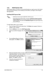
... you want to continue. 5. Select your computer. 2. Click Next to install Express Gate. See section 1.2.1 Motherboard layout for Express Gate appears. Select the target drive where you have multiple partitions installed on your computer: 1. ASUS M2N68-AM SE 1-16 Click Next to complete the installation. The Drivers menu appears if Autorun is enabled on...
... you want to continue. 5. Select your computer. 2. Click Next to install Express Gate. See section 1.2.1 Motherboard layout for Express Gate appears. Select the target drive where you have multiple partitions installed on your computer: 1. ASUS M2N68-AM SE 1-16 Click Next to complete the installation. The Drivers menu appears if Autorun is enabled on...
User Manual
Page 27
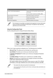
... static IP. Drag any RJ-45 port, and Express Gate automatically uses the available port. Enable all the network ports that you may differ from motherboards. • You can connect the LAN cable to open a particular configuration tool. TO Launch or switch between applications Bring a window to this application without delay... the LaunchBar located at the bottom of the window's four corners. Using the Configuration Panel Use the configuration panel to change the Express Gate settings. ASUS M2N68-AM SE 1-18
... static IP. Drag any RJ-45 port, and Express Gate automatically uses the available port. Enable all the network ports that you may differ from motherboards. • You can connect the LAN cable to open a particular configuration tool. TO Launch or switch between applications Bring a window to this application without delay... the LaunchBar located at the bottom of the window's four corners. Using the Configuration Panel Use the configuration panel to change the Express Gate settings. ASUS M2N68-AM SE 1-18

User Manual
Page 30
... DSL/ cable modem, enable all the LAN ports. Express Gate automatically uses the available port. • The number of the LAN ports vary with the motherboard. • If you use a network cable connected to configure the static IP settings manually. Network 3. If your computer does not automatically get network settings from...
... DSL/ cable modem, enable all the LAN ports. Express Gate automatically uses the available port. • The number of the LAN ports vary with the motherboard. • If you use a network cable connected to configure the static IP settings manually. Network 3. If your computer does not automatically get network settings from...
User Manual
Page 31
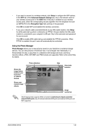
...your hard drive or external devices Shows usercreated image albums Photo slideshow Help View mode selection Image control bar ASUS Express Gate supports HDDs connected to the online Help for xDSL/cable dial-up and establish the PPPoE ...SATA ports and external SATA ports are supported. When PPPoE is enabled on your computer's LAN port. Refer to motherboard chipset-controlled onboard SATA ports only. Shows the image folders found on your DSL/cable modem, click Setup for...will automatically be unchecked. JPEG, GIF, BMP, and PNG formats are NOT supported. ASUS M2N68-AM SE 1-22
...your hard drive or external devices Shows usercreated image albums Photo slideshow Help View mode selection Image control bar ASUS Express Gate supports HDDs connected to the online Help for xDSL/cable dial-up and establish the PPPoE ...SATA ports and external SATA ports are supported. When PPPoE is enabled on your computer's LAN port. Refer to motherboard chipset-controlled onboard SATA ports only. Shows the image folders found on your DSL/cable modem, click Setup for...will automatically be unchecked. JPEG, GIF, BMP, and PNG formats are NOT supported. ASUS M2N68-AM SE 1-22

User Manual
Page 33
...Internet a. c. From the FTP site, select the BIOS version you update the BIOS using the ASUS Update utility. 2.1.1 ASUS Update utility The ASUS Update is a utility that comes with the motherboard package. The Drivers menu appears. 2. Always update the utility to get all Windows® ...Select then click Next. Copy the original motherboard BIOS using this utility. b. The ASUS Update utility is available in the Support DVD that allows you to manage, save, and update the motherboard BIOS in Windows® environment. • ASUS Update requires an Internet connection either of ...
...Internet a. c. From the FTP site, select the BIOS version you update the BIOS using the ASUS Update utility. 2.1.1 ASUS Update utility The ASUS Update is a utility that comes with the motherboard package. The Drivers menu appears. 2. Always update the utility to get all Windows® ...Select then click Next. Copy the original motherboard BIOS using this utility. b. The ASUS Update utility is available in the Support DVD that allows you to manage, save, and update the motherboard BIOS in Windows® environment. • ASUS Update requires an Internet connection either of ...
User Manual
Page 35
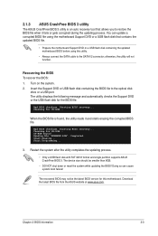
...restore the BIOS file when it and starts erasing the corrupted BIOS file. Doing so can update a corrupted BIOS file using this motherboard. You can cause system boot failure! otherwise, the utility will not function. Restart the system after the utility completes the updating process... updated motherboard BIOS before using the motherboard Support DVD or a USB flash disk that allows you to the SATA1/2 connector; Start Programming... 3. The device size should be the latest BIOS version for CD-ROM... Download the latest BIOS file from the ASUS website at www.asus.com...
...restore the BIOS file when it and starts erasing the corrupted BIOS file. Doing so can update a corrupted BIOS file using this motherboard. You can cause system boot failure! otherwise, the utility will not function. Restart the system after the utility completes the updating process... updated motherboard BIOS before using the motherboard Support DVD or a USB flash disk that allows you to the SATA1/2 connector; Start Programming... 3. The device size should be the latest BIOS version for CD-ROM... Download the latest BIOS file from the ASUS website at www.asus.com...

User Manual
Page 36
...the power button, reset button, or the ++ keys to force reset from the operating system. • The default BIOS settings for this motherboard. 2.3 Main menu When you enter the BIOS Setup program, the Main menu screen appears, giving you an overview of the following procedures: ...the system becomes unstable after POST, reboot the system by doing any BIOS settings, load the default settings to set the system date. 2-4 ASUS M2N68-AM SE See section 2.8 Exit menu. • The BIOS setup screens in this utility. Primary IDE Master Primary IDE Slave SATA1 SATA2 System Information ...
...the power button, reset button, or the ++ keys to force reset from the operating system. • The default BIOS settings for this motherboard. 2.3 Main menu When you enter the BIOS Setup program, the Main menu screen appears, giving you an overview of the following procedures: ...the system becomes unstable after POST, reboot the system by doing any BIOS settings, load the default settings to set the system date. 2-4 ASUS M2N68-AM SE See section 2.8 Exit menu. • The BIOS setup screens in this utility. Primary IDE Master Primary IDE Slave SATA1 SATA2 System Information ...


