
User Manual
Page 1
Motherboard
Motherboard
User Manual
Page 3
Contents Notices...v Safety information vi About this guide vi M2N68-AM PLUS specifications summary viii Chapter 1: Product introduction 1.1 Before you proceed 1-1 1.2 Motherboard overview 1-2 1.2.1 Motherboard layout 1-2 1.2.2 Layout contents 1-2 1.3 Central Processing Unit (CPU 1-3 1.4 System memory 1-3 1.4.1 Overview 1-3 1.4.2 Memory configurations 1-3... DVD information 1-15 Chapter 2: BIOS information 2.1 Managing and updating your BIOS 2-1 2.1.1 ASUS Update utility 2-1 2.1.2 ASUS EZ Flash 2 utility 2-2 2.1.3 ASUS CrashFree BIOS 3 utility 2-3 2.2 BIOS setup program 2-4 iii
Contents Notices...v Safety information vi About this guide vi M2N68-AM PLUS specifications summary viii Chapter 1: Product introduction 1.1 Before you proceed 1-1 1.2 Motherboard overview 1-2 1.2.1 Motherboard layout 1-2 1.2.2 Layout contents 1-2 1.3 Central Processing Unit (CPU 1-3 1.4 System memory 1-3 1.4.1 Overview 1-3 1.4.2 Memory configurations 1-3... DVD information 1-15 Chapter 2: BIOS information 2.1 Managing and updating your BIOS 2-1 2.1.1 ASUS Update utility 2-1 2.1.2 ASUS EZ Flash 2 utility 2-2 2.1.3 ASUS CrashFree BIOS 3 utility 2-3 2.2 BIOS setup program 2-4 iii
User Manual
Page 5
DO NOT throw the motherboard in municipal waste. Check local regulations for radio noise emissions from that to assure compliance with manufacturer's instructions, may cause undesired operation. Operation is required ...
DO NOT throw the motherboard in municipal waste. Check local regulations for radio noise emissions from that to assure compliance with manufacturer's instructions, may cause undesired operation. Operation is required ...
User Manual
Page 6
... service technician or your dealer immediately. • To avoid short circuits, keep paper clips, screws, and staples away from the motherboard, ensure that the power cables for the devices are unplugged before the signal cables are unplugged. • Seek professional assistance before you... need when installing and configuring the motherboard. If you encounter technical problems with the package. • Before using , contact your local power company. • If ...
... service technician or your dealer immediately. • To avoid short circuits, keep paper clips, screws, and staples away from the motherboard, ensure that the power cables for the devices are unplugged before the signal cables are unplugged. • Seek professional assistance before you... need when installing and configuring the motherboard. If you encounter technical problems with the package. • Before using , contact your local power company. • If ...
User Manual
Page 8
... 32-bit and 64-bit computing AMD Cool 'n' Quiet™ Technology * Refer to www.asus.com for AMD CPU support list GeForce 7025 / NVIDIA nForce 630a 2000 / 1600 MT/s Dual... Multistreaming Technologies. For effective use of memory, we recommend that you install 4GB or more memory installed on the motherboard. 1 x PCI Express™ x16 slot 1 x PCI Express™ x1 slot 2 x PCI slots 1...0, RAID 1, RAID 10, RAID 5 (only for the OS can be about 3GB or less. M2N68-AM PLUS specifications summary CPU Chipset System bus Memory Expansion slots Storage / RAID Audio USB LAN Back panel I /O ...
... 32-bit and 64-bit computing AMD Cool 'n' Quiet™ Technology * Refer to www.asus.com for AMD CPU support list GeForce 7025 / NVIDIA nForce 630a 2000 / 1600 MT/s Dual... Multistreaming Technologies. For effective use of memory, we recommend that you install 4GB or more memory installed on the motherboard. 1 x PCI Express™ x16 slot 1 x PCI Express™ x1 slot 2 x PCI slots 1...0, RAID 1, RAID 10, RAID 5 (only for the OS can be about 3GB or less. M2N68-AM PLUS specifications summary CPU Chipset System bus Memory Expansion slots Storage / RAID Audio USB LAN Back panel I /O ...
User Manual
Page 10
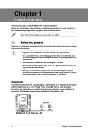
... the power supply. The illustration below shows the location of the onboard LED. 1-1 Chapter 1: Product introduction Refer to page ix for buying an ASUS® M2N68-AM PLUS motherboard! If any motherboard component. Before you must shut down the system and unplug the power cable before handling components to avoid damaging them due to static...
... the power supply. The illustration below shows the location of the onboard LED. 1-1 Chapter 1: Product introduction Refer to page ix for buying an ASUS® M2N68-AM PLUS motherboard! If any motherboard component. Before you must shut down the system and unplug the power cable before handling components to avoid damaging them due to static...
User Manual
Page 11
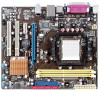
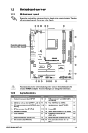
...(4-pin CPU_FAN) 1-11 12. 1.2 1.2.1 Motherboard overview Motherboard layout Ensure that you install the motherboard into the holes indicated by circles to secure the motherboard to the rear part of the chassis. Doing so can damage the motherboard. 1.2.2 Layout contents Connectors/Jumpers/Slots Page ...chassis in the correct orientation. Front panel audio connector (10-1 pin AAFP) Page 1-11 1-7 1-12 1-1 1-13 1-14 1-10 1-13 ASUS M2N68-AM PLUS 1-2 Onboard LED 5. DDR2 DIMM slots 1-3 14. Keyboard/mouse power (3-pin KBPWR) 1-8 9. System panel connector (10-1 pin PANEL) ...
...(4-pin CPU_FAN) 1-11 12. 1.2 1.2.1 Motherboard overview Motherboard layout Ensure that you install the motherboard into the holes indicated by circles to secure the motherboard to the rear part of the chassis. Doing so can damage the motherboard. 1.2.2 Layout contents Connectors/Jumpers/Slots Page ...chassis in the correct orientation. Front panel audio connector (10-1 pin AAFP) Page 1-11 1-7 1-12 1-1 1-13 1-14 1-10 1-13 ASUS M2N68-AM PLUS 1-2 Onboard LED 5. DDR2 DIMM slots 1-3 14. Keyboard/mouse power (3-pin KBPWR) 1-8 9. System panel connector (10-1 pin PANEL) ...
User Manual
Page 12
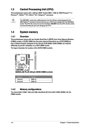
..., 1GB, and 2GB unbuffered ECC/non-ECC DDR2 DIMMs into the socket to prevent bending the pins and damaging the CPU! 1.4 System memory 1.4.1 Overview This motherboard comes with a 940-pin AMD® Socket AM2+ / AM2 for AMD Phenom™ II / Phenom™ / Athlon™ FX / Athlon™ 64 ...for the AM2/AM2+ socket. Ensure that you use a CPU that is designed for the AMD Opteron™ processor. 1.3 Central Processing Unit (CPU) This motherboard comes with two Double Data Rate 2 (DDR2) Dual Inline Memory Modules (DIMM) sockets. DO NOT force the CPU into the DIMM sockets. 1-3 Chapter ...
..., 1GB, and 2GB unbuffered ECC/non-ECC DDR2 DIMMs into the socket to prevent bending the pins and damaging the CPU! 1.4 System memory 1.4.1 Overview This motherboard comes with a 940-pin AMD® Socket AM2+ / AM2 for AMD Phenom™ II / Phenom™ / Athlon™ FX / Athlon™ 64 ...for the AM2/AM2+ socket. Ensure that you use a CPU that is designed for the AMD Opteron™ processor. 1.3 Central Processing Unit (CPU) This motherboard comes with two Double Data Rate 2 (DDR2) Dual Inline Memory Modules (DIMM) sockets. DO NOT force the CPU into the DIMM sockets. 1-3 Chapter ...
User Manual
Page 13
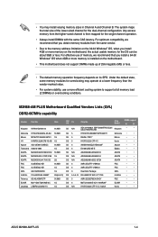
... less. Under the default state, some memory modules for overclocking may install varying memory sizes in Channel A and Channel B. Size SS/ DS CL Chip No. M2N68-AM PLUS Motherboard Qualified Vendors Lists (QVL) DDR2-667MHz capability Vendor Part No. • You may operate at a lower frequency than the vendor-marked value. • For... 5 A3R12E3GEF633ACAOY PSC • • ELIXIR M2Y1G64TU8HA2B-3C 1G DS 5 M2TU51280AE-3C717095R28F ELIXIR • • Leadmax LRMP512U64A8-Y5 1G DS N/A HY5PS12821CFP-Y5 C 702AA Hynix • • ASUS M2N68-AM PLUS 1-4
... less. Under the default state, some memory modules for overclocking may install varying memory sizes in Channel A and Channel B. Size SS/ DS CL Chip No. M2N68-AM PLUS Motherboard Qualified Vendors Lists (QVL) DDR2-667MHz capability Vendor Part No. • You may operate at a lower frequency than the vendor-marked value. • For... 5 A3R12E3GEF633ACAOY PSC • • ELIXIR M2Y1G64TU8HA2B-3C 1G DS 5 M2TU51280AE-3C717095R28F ELIXIR • • Leadmax LRMP512U64A8-Y5 1G DS N/A HY5PS12821CFP-Y5 C 702AA Hynix • • ASUS M2N68-AM PLUS 1-4
User Manual
Page 15
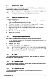
... card. Assign an IRQ to unplug the power cord before adding or removing expansion cards. ASUS M2N68-AM PLUS 1-6 Ensure to the card. 3. Remove the chassis cover (if your motherboard is completely seated on shared slots, ensure that the drivers support "Share IRQ" or that...is already installed in a chassis). 3. The following sub-sections describe the slots and the expansion cards that you physical injury and damage motherboard components. 1.5.1 Installing an expansion card To install an expansion card: 1. Align the card connector with the screw. 6. Secure the card...
... card. Assign an IRQ to unplug the power cord before adding or removing expansion cards. ASUS M2N68-AM PLUS 1-6 Ensure to the card. 3. Remove the chassis cover (if your motherboard is completely seated on shared slots, ensure that the drivers support "Share IRQ" or that...is already installed in a chassis). 3. The following sub-sections describe the slots and the expansion cards that you physical injury and damage motherboard components. 1.5.1 Installing an expansion card To install an expansion card: 1. Align the card connector with the screw. 6. Secure the card...
User Manual
Page 19
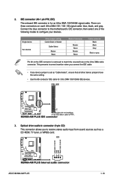
Connect the blue connector to the motherboard's IDE connector, then select one of device(s) - Single device Two devices Drive jumper setting Cable-Select or Master Cable-Select Master Slave Mode of the ... Master Slave Cable connector Black Black Gray Black or gray Pin 20 on the IDE connector is for Ultra DMA 133/100/66 IDE devices. 3. ASUS M2N68-AM PLUS 1-10 2. IDE connector (40-1 pin PRI_IDE) The onboard IDE connector is removed to configure your devices.
Connect the blue connector to the motherboard's IDE connector, then select one of device(s) - Single device Two devices Drive jumper setting Cable-Select or Master Cable-Select Master Slave Mode of the ... Master Slave Cable connector Black Black Gray Black or gray Pin 20 on the IDE connector is for Ultra DMA 133/100/66 IDE devices. 3. ASUS M2N68-AM PLUS 1-10 2. IDE connector (40-1 pin PRI_IDE) The onboard IDE connector is removed to configure your devices.
User Manual
Page 20
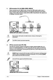
... the CPU fan connector on the CPU fan connector. Insufficient air flow inside the system may damage the motherboard components. These USB connectors comply with the USB 2.0 specification that the black wire of each cable matches ... (26.64W max.) at the back of the system chassis. DO NOT place a jumper cap on the motherboard, ensuring that supports up to a slot opening at +12V. Connect the USB module cable to any of ...cable to the CPU fan connector. Only the CPU fan supports the ASUS Q-Fan feature. 1-11 Chapter 1: Product introduction Doing so will damage the motherboard! 4.
... the CPU fan connector on the CPU fan connector. Insufficient air flow inside the system may damage the motherboard components. These USB connectors comply with the USB 2.0 specification that the black wire of each cable matches ... (26.64W max.) at the back of the system chassis. DO NOT place a jumper cap on the motherboard, ensuring that supports up to a slot opening at +12V. Connect the USB module cable to any of ...cable to the CPU fan connector. Only the CPU fan supports the ASUS Q-Fan feature. 1-11 Chapter 1: Product introduction Doing so will damage the motherboard! 4.
User Manual
Page 24
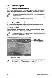
...change at any time without notice. The contents of the Support DVD are subject to get all motherboard features. 1.8 Software support 1.8.1 Installing an operating system This motherboard supports Windows® XP/Vista Operating Systems (OS). Double-click ASSETUP.EXE to maximize the features...DVD Place the Support DVD into the optical drive. Visit the ASUS website at www.asus.com for better compatibility and system stability. 1.8.2 Support DVD information The Support DVD that comes with the motherboard package contains drivers, software applications, and utilities that you install ...
...change at any time without notice. The contents of the Support DVD are subject to get all motherboard features. 1.8 Software support 1.8.1 Installing an operating system This motherboard supports Windows® XP/Vista Operating Systems (OS). Double-click ASSETUP.EXE to maximize the features...DVD Place the Support DVD into the optical drive. Visit the ASUS website at www.asus.com for better compatibility and system stability. 1.8.2 Support DVD information The Support DVD that comes with the motherboard package contains drivers, software applications, and utilities that you install ...
User Manual
Page 25
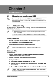
... all Windows® applications before you update the BIOS using the ASUS Update utility.. 2.1.1 ASUS Update utility The ASUS Update is a utility that comes with the motherboard package. Follow the onscreen instructions to launch the ASUS Update utility. 2. Select Update BIOS from the Internet a. c....drive. From the Windows® desktop, Click Start > Programs > ASUS > ASUS Update > ASUS Update to complete the installation. Chapter 2 BIOS information 2.1 Managing and updating your BIOS Save a copy of the original motherboard BIOS file to a bootable USB flash disk in case you need ...
... all Windows® applications before you update the BIOS using the ASUS Update utility.. 2.1.1 ASUS Update utility The ASUS Update is a utility that comes with the motherboard package. Follow the onscreen instructions to launch the ASUS Update utility. 2. Select Update BIOS from the Internet a. c....drive. From the Windows® desktop, Click Start > Programs > ASUS > ASUS Update > ASUS Update to complete the installation. Chapter 2 BIOS information 2.1 Managing and updating your BIOS Save a copy of the original motherboard BIOS file to a bootable USB flash disk in case you need ...
User Manual
Page 27
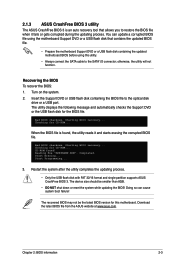
...corrupted during the updating process. otherwise, the utility will not function. Start Erasing... Doing so can update a corrupted BIOS file using the motherboard Support DVD or a USB flash disk that allows you to the optical disk drive or a USB port. Starting BIOS recovery... Download ...the latest BIOS file from the ASUS website at www.asus.com. 2.1.3 ASUS CrashFree BIOS 3 utility The ASUS CrashFree BIOS 3 is found ! Insert the Support DVD or USB flash disk containing the BIOS file to ...
...corrupted during the updating process. otherwise, the utility will not function. Start Erasing... Doing so can update a corrupted BIOS file using the motherboard Support DVD or a USB flash disk that allows you to the optical disk drive or a USB port. Starting BIOS recovery... Download ...the latest BIOS file from the ASUS website at www.asus.com. 2.1.3 ASUS CrashFree BIOS 3 utility The ASUS CrashFree BIOS 3 is found ! Insert the Support DVD or USB flash disk containing the BIOS file to ...
User Manual
Page 28
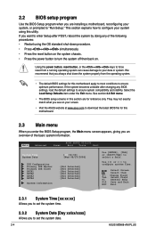
... 2.8 Exit menu. • The BIOS setup screens in this section are installing a motherboard, reconfiguring your screen. • Visit the ASUS website at www.asus.com to ensure optimum performance. Main Advanced Power BIOS SETUP UTILITY Boot Tools Exit System Time...latest BIOS file for reference only. 2.2 BIOS setup program Use the BIOS Setup program when you are for this motherboard. 2.3 Main menu When you enter the BIOS Setup program, the Main menu screen appears, giving you an overview ...a running operating system can cause damage to set the system date. 2-4 ASUS M2N68-AM PLUS
... 2.8 Exit menu. • The BIOS setup screens in this section are installing a motherboard, reconfiguring your screen. • Visit the ASUS website at www.asus.com to ensure optimum performance. Main Advanced Power BIOS SETUP UTILITY Boot Tools Exit System Time...latest BIOS file for reference only. 2.2 BIOS setup program Use the BIOS Setup program when you are for this motherboard. 2.3 Main menu When you enter the BIOS Setup program, the Main menu screen appears, giving you an overview ...a running operating system can cause damage to set the system date. 2-4 ASUS M2N68-AM PLUS
User Manual
Page 36
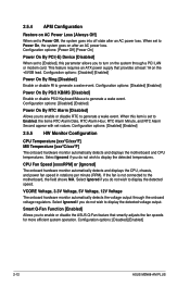
...to [Enabled], this item is not connected to the motherboard, the field shows N/A. Configuration options: [Disabled] [Enabled] Power On By Ring [Disabled] Enable or disable RI to enable or disable the ASUS Q-Fan feature that provides at least 1A on after an... options: [Disabled] [Enabled] 2-12 ASUS M2N68-AM PLUS Configuration options: [Disabled] [Enabled] 2.5.5 HW Monitor Configuration CPU Temperature [xxxºC/xxxºF] MB Temperature [xxxºC/xxxºF] The onboard hardware monitor automatically detects and displays the motherboard and CPU temperatures. CPU Fan Speed [...
...to [Enabled], this item is not connected to the motherboard, the field shows N/A. Configuration options: [Disabled] [Enabled] Power On By Ring [Disabled] Enable or disable RI to enable or disable the ASUS Q-Fan feature that provides at least 1A on after an... options: [Disabled] [Enabled] 2-12 ASUS M2N68-AM PLUS Configuration options: [Disabled] [Enabled] 2.5.5 HW Monitor Configuration CPU Temperature [xxxºC/xxxºF] MB Temperature [xxxºC/xxxºF] The onboard hardware monitor automatically detects and displays the motherboard and CPU temperatures. CPU Fan Speed [...


