User Manual
Page 12
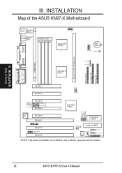
...Lithium Cell Battery Test Parallel Port COM 2 DIMM Socket Intel 440FX PCIset CPU_FAN PWR_FAN Pentium II CPU Cartridge Slot Floppy Drives Secondary IDE Primary IDE Game/Midi Port Mic Line In Line Out PCI Slot 1 PCI Slot 2 FS0 FS1 BUS FREQ 3D Sound Panasonic CD In PCI Slot 3 Sony... Slot 1 Flash ROM for ATX Power Supply 01234 CPU Voltage ID Intel 440FX PCIset BF0 BF1 BF2 BF3 BUS FREQ. III. INSTALLATION (Map of the ASUS KN97-X Motherboard COM 1 Top: Mouse PS/2 Bottom: Keyboard Top: USB 1 USB Bottom: USB 2 Board Power Input for BIOS R ISA Slot 2 Creative® Modem Connector...
...Lithium Cell Battery Test Parallel Port COM 2 DIMM Socket Intel 440FX PCIset CPU_FAN PWR_FAN Pentium II CPU Cartridge Slot Floppy Drives Secondary IDE Primary IDE Game/Midi Port Mic Line In Line Out PCI Slot 1 PCI Slot 2 FS0 FS1 BUS FREQ 3D Sound Panasonic CD In PCI Slot 3 Sony... Slot 1 Flash ROM for ATX Power Supply 01234 CPU Voltage ID Intel 440FX PCIset BF0 BF1 BF2 BF3 BUS FREQ. III. INSTALLATION (Map of the ASUS KN97-X Motherboard COM 1 Top: Mouse PS/2 Bottom: Keyboard Top: USB 1 USB Bottom: USB 2 Board Power Input for BIOS R ISA Slot 2 Creative® Modem Connector...

User Manual
Page 13
ASUS KN97-X User's Manual 13 III. INSTALLATION (Map of these two slots must not use this address or else conflicts will occur. *PCI NOTE: PCI slots 4&5 share ... (CPU) Cartridge Support p. 24 16-bit ISA Bus Expansion Slots* p. 24 32-bit PCI Bus Expansion Slots* Connectors 1) PS2KEYBOARD 2) PS2MOUSE 3) PRINTER 4) COM1, COM2 5) AUDIO (optional) 6) GAME (optional) 7) USB 8) FLOPPY 9) FANPWR1, 2, 3 10) CHASSIS 11) IDE1, IDE2 12) IDELED 13) PWR LED (PANEL) 14) SMI (PANEL) 15) PWR SW (CON1) 16) RESET (PANEL...
ASUS KN97-X User's Manual 13 III. INSTALLATION (Map of these two slots must not use this address or else conflicts will occur. *PCI NOTE: PCI slots 4&5 share ... (CPU) Cartridge Support p. 24 16-bit ISA Bus Expansion Slots* p. 24 32-bit PCI Bus Expansion Slots* Connectors 1) PS2KEYBOARD 2) PS2MOUSE 3) PRINTER 4) COM1, COM2 5) AUDIO (optional) 6) GAME (optional) 7) USB 8) FLOPPY 9) FANPWR1, 2, 3 10) CHASSIS 11) IDE1, IDE2 12) IDELED 13) PWR LED (PANEL) 14) SMI (PANEL) 15) PWR SW (CON1) 16) RESET (PANEL...
User Manual
Page 30
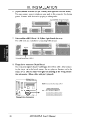
... inserting in the wrong orientation when using ribbon cables with optional onboard Audio) You may connect game joysticks or game pads to Pin 1 Floppy Drive Connector Pin 1 30 ASUS KN97-X User's Manual Joystick/Midi (15-pin Female) 7. INSTALLATION (Connectors) III. Floppy Drive ...Connector NOTE: Connect the Red stripe to this connector for playing games. INSTALLATION 6. Universal Serial BUS Ports 1 & 2 (Two 4-pin ...
... inserting in the wrong orientation when using ribbon cables with optional onboard Audio) You may connect game joysticks or game pads to Pin 1 Floppy Drive Connector Pin 1 30 ASUS KN97-X User's Manual Joystick/Midi (15-pin Female) 7. INSTALLATION (Connectors) III. Floppy Drive ...Connector NOTE: Connect the Red stripe to this connector for playing games. INSTALLATION 6. Universal Serial BUS Ports 1 & 2 (Two 4-pin ...