User Manual
Page 12
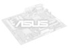
... Fan Volume Control Infrared Connect Hardware Monitor IDE LED Panel NOTE: The items in Outline are available only with the optional onboard Audio. 12 ASUS KN97-X User's Manual INSTALLATION Map of Board) III. CR2032 3 Volt Lithium Cell Battery Test Parallel Port COM 2 DIMM Socket Intel 440FX PCIset ...CPU_FAN PWR_FAN Pentium II CPU Cartridge Slot Floppy Drives Secondary IDE Primary IDE Game/Midi Port Mic Line In Line Out PCI Slot 1 PCI Slot 2 FS0 FS1 BUS FREQ 3D Sound Panasonic CD In PCI Slot 3...
... Fan Volume Control Infrared Connect Hardware Monitor IDE LED Panel NOTE: The items in Outline are available only with the optional onboard Audio. 12 ASUS KN97-X User's Manual INSTALLATION Map of Board) III. CR2032 3 Volt Lithium Cell Battery Test Parallel Port COM 2 DIMM Socket Intel 440FX PCIset ...CPU_FAN PWR_FAN Pentium II CPU Cartridge Slot Floppy Drives Secondary IDE Primary IDE Game/Midi Port Mic Line In Line Out PCI Slot 1 PCI Slot 2 FS0 FS1 BUS FREQ 3D Sound Panasonic CD In PCI Slot 3...

User Manual
Page 13
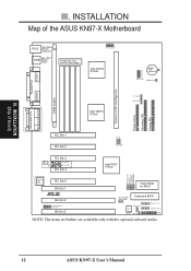
... (CPU) Cartridge Support p. 24 16-bit ISA Bus Expansion Slots* p. 24 32-bit PCI Bus Expansion Slots* Connectors 1) PS2KEYBOARD 2) PS2MOUSE 3) PRINTER 4) COM1, COM2 5) AUDIO (optional) 6) GAME (optional) 7) USB 8) FLOPPY 9) FANPWR1, 2, 3 10) CHASSIS 11) IDE1, IDE2 12) IDELED 13) PWR LED (PANEL) 14) SMI (PANEL) 15) PWR SW (CON1) 16) RESET (PANEL... use an INT#. III. INSTALLATION (Map of these two slots must be able to share an INT# or make sure that one of Board) III. ASUS KN97-X User's Manual 13
... (CPU) Cartridge Support p. 24 16-bit ISA Bus Expansion Slots* p. 24 32-bit PCI Bus Expansion Slots* Connectors 1) PS2KEYBOARD 2) PS2MOUSE 3) PRINTER 4) COM1, COM2 5) AUDIO (optional) 6) GAME (optional) 7) USB 8) FLOPPY 9) FANPWR1, 2, 3 10) CHASSIS 11) IDE1, IDE2 12) IDELED 13) PWR LED (PANEL) 14) SMI (PANEL) 15) PWR SW (CON1) 16) RESET (PANEL... use an INT#. III. INSTALLATION (Map of these two slots must be able to share an INT# or make sure that one of Board) III. ASUS KN97-X User's Manual 13
User Manual
Page 30
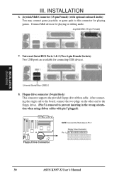
...Pin 5 is removed to Pin 1 Floppy Drive Connector Pin 1 30 ASUS KN97-X User's Manual INSTALLATION (Connectors) III. Universal Serial BUS Ports 1 & 2 (Two 4-pin Female Sockets) Two USB ports are available for playing games. Floppy Drive Connector NOTE: Connect the Red stripe to prevent inserting ...in the wrong orientation when using ribbon cables with optional onboard Audio) You may connect game joysticks or game pads to this connector for connecting USB devices. Connect Midi devices for playing or editing audio. USB 1 Univeral Serial Bus ...
...Pin 5 is removed to Pin 1 Floppy Drive Connector Pin 1 30 ASUS KN97-X User's Manual INSTALLATION (Connectors) III. Universal Serial BUS Ports 1 & 2 (Two 4-pin Female Sockets) Two USB ports are available for playing games. Floppy Drive Connector NOTE: Connect the Red stripe to prevent inserting ...in the wrong orientation when using ribbon cables with optional onboard Audio) You may connect game joysticks or game pads to this connector for connecting USB devices. Connect Midi devices for playing or editing audio. USB 1 Univeral Serial Bus ...