
K7M User Manual
Page 1
R K7M Slot A Motherboard USER'S MANUAL
R K7M Slot A Motherboard USER'S MANUAL

K7M User Manual
Page 4
... Expansion Cards 31 3.7.3 Assigning DMA Channels for Slot A Processors 29 3.7. FEATURES 8 2.1 The ASUS K7M Motherboard 8 2.1.1 Specifications 8 2.1.1.1 Optional Components 9 2.1.2 Performance 10 2.1.3 Intelligence (only with optional hardware monitor) ........ 11 2.2 Motherboard Parts 12 3. HARDWARE SETUP 14 3.1 Motherboard Layout 14 3.2 Layout Contents 15 3.3 Hardware Setup Procedure 17 3.4 Motherboard Settings 17 3.5 System Memory (DIMM 22 3.5.1 General DIMM Notes 22 3.5.2 DIMM Memory...
... Expansion Cards 31 3.7.3 Assigning DMA Channels for Slot A Processors 29 3.7. FEATURES 8 2.1 The ASUS K7M Motherboard 8 2.1.1 Specifications 8 2.1.1.1 Optional Components 9 2.1.2 Performance 10 2.1.3 Intelligence (only with optional hardware monitor) ........ 11 2.2 Motherboard Parts 12 3. HARDWARE SETUP 14 3.1 Motherboard Layout 14 3.2 Layout Contents 15 3.3 Hardware Setup Procedure 17 3.4 Motherboard Settings 17 3.5 System Memory (DIMM 22 3.5.1 General DIMM Notes 22 3.5.2 DIMM Memory...
K7M User Manual
Page 7
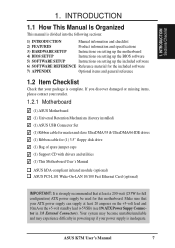
...missing items, please contact your retailer. 1.2.1 Motherboard (1) ASUS Motherboard (1) Universal Retention Mechanism (factory installed) (1) ASUS USB Connector Set (1) Ribbon cable for master and slave UltraDMA/33 & UltraDMA/66 IDE drives (1) Ribbon cable for this motherboard. ASUS K7M User's Manual 7 INTRODUCTION Sections/Checklist 1. ...3) HARDWARE SETUP Instructions on setting up the motherboard 4) BIOS SETUP Instructions on setting up the BIOS software 5) SOFTWARE SETUP Instructions on the +5-volt standby lead (+5VSB) (see 19) ATX Power Suppy Connector in powering up the included...
...missing items, please contact your retailer. 1.2.1 Motherboard (1) ASUS Motherboard (1) Universal Retention Mechanism (factory installed) (1) ASUS USB Connector Set (1) Ribbon cable for master and slave UltraDMA/33 & UltraDMA/66 IDE drives (1) Ribbon cable for this motherboard. ASUS K7M User's Manual 7 INTRODUCTION Sections/Checklist 1. ...3) HARDWARE SETUP Instructions on setting up the motherboard 4) BIOS SETUP Instructions on setting up the BIOS software 5) SOFTWARE SETUP Instructions on the +5-volt standby lead (+5VSB) (see 19) ATX Power Suppy Connector in powering up the included...
K7M User Manual
Page 8
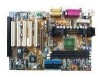
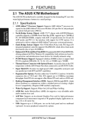
... ports and one parallel port with support for more peripheral connectivity options. 8 ASUS K7M User's Manual FEATURES 2.1 The ASUS K7M Motherboard The ASUS K7M motherboard is optimized to deliver enhanced AMD Athlon™ processor system performance. • South Bridge System Chipset: VIA VT82C686A PCIset with the ASUS Smart Fan when connected to 4 USB ports, two on the back panel...
... ports and one parallel port with support for more peripheral connectivity options. 8 ASUS K7M User's Manual FEATURES 2.1 The ASUS K7M Motherboard The ASUS K7M motherboard is optimized to deliver enhanced AMD Athlon™ processor system performance. • South Bridge System Chipset: VIA VT82C686A PCIset with the ASUS Smart Fan when connected to 4 USB ports, two on the back panel...

K7M User Manual
Page 9
..., and Tape Backup drives. • Smart BIOS: 2Mb firmware gives a new easy-to meet PC 99 compliancy, major connectors in this motherboard are color-coded. 2.1.1.1 Optional Components The following onboard components are supported midboard. Provides CPU/SDRAM frequency adjustments, and HD/SCSI/ZIP/CD/Floppy...IDE devices, such as CPU and system voltages, temperatures, and fan status through the onboard hardware ASIC and the bundled ASUS PC Probe. • Additional USB Ports: For more control and protection over the motherboard. FEATURES Specifications 2. ASUS K7M User's Manual 9
..., and Tape Backup drives. • Smart BIOS: 2Mb firmware gives a new easy-to meet PC 99 compliancy, major connectors in this motherboard are color-coded. 2.1.1.1 Optional Components The following onboard components are supported midboard. Provides CPU/SDRAM frequency adjustments, and HD/SCSI/ZIP/CD/Floppy...IDE devices, such as CPU and system voltages, temperatures, and fan status through the onboard hardware ASIC and the bundled ASUS PC Probe. • Additional USB Ports: For more control and protection over the motherboard. FEATURES Specifications 2. ASUS K7M User's Manual 9
K7M User Manual
Page 10
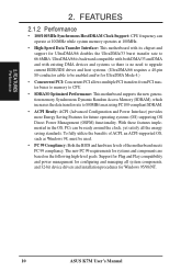
...8226; Concurrent PCI: Concurrent PCI allows multiple PCI transfers from PCI master buses to memory to CPU. • SDRAM Optimized Performance: This motherboard supports the new generation memory, Synchronous Dynamic Random Access Memory (SDRAM), which increases the data transfer rate to 66.6MB/s. With these features... SDRAM. • ACPI Ready: ACPI (Advanced Configuration and Power Interface) provides more Energy Saving Features for Windows 95/98/NT. 10 ASUS K7M User's Manual To fully utilize the benefits of ACPI, an ACPI-supported OS, such as Windows 98, must be ready around the clock...
...8226; Concurrent PCI: Concurrent PCI allows multiple PCI transfers from PCI master buses to memory to CPU. • SDRAM Optimized Performance: This motherboard supports the new generation memory, Synchronous Dynamic Random Access Memory (SDRAM), which increases the data transfer rate to 66.6MB/s. With these features... SDRAM. • ACPI Ready: ACPI (Advanced Configuration and Power Interface) provides more Energy Saving Features for Windows 95/98/NT. 10 ASUS K7M User's Manual To fully utilize the benefits of ACPI, an ACPI-supported OS, such as Windows 98, must be ready around the clock...
K7M User Manual
Page 11
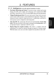
FEATURES Intelligence ASUS K7M User's Manual 11 All the fans are monitored to ensure stable current to implement...system voltage levels are set for future processors, so monitoring is an important feature to critical motherboard components. This function reduces both energy consumption and system noise, and is necessary to be monitored for RPM ...and failure. With this motherboard to ensure proper system configuration and management. • Auto Fan Off: The system fans will power off...
FEATURES Intelligence ASUS K7M User's Manual 11 All the fans are monitored to ensure stable current to implement...system voltage levels are set for future processors, so monitoring is an important feature to critical motherboard components. This function reduces both energy consumption and system noise, and is necessary to be monitored for RPM ...and failure. With this motherboard to ensure proper system configuration and management. • Auto Fan Off: The system fans will power off...
K7M User Manual
Page 12
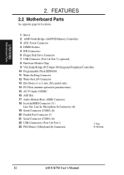
FEATURES Motherboard Parts 2. FEATURES 2.2 Motherboard Parts See opposite page for locations. 1 Slot A 2 AMD North Bridge (AGP/PCI/Memory Controller) 3 ATX Power Connector 4 DIMM Sockets 5 IDE Connectors 6 Floppy Disk Drive Connector 7 USB Connector (Port 2 & Port 3) (optional) 8 Hardware Monitor Chip 9 VIA South Bridge (PCI Super I/O Integrated Peripheral... 19 Serial Connector (COM2) (B) 20 Parallel Port Connector (T) 21 Serial Connector (COM1) (B) 22 USB Connnectors (Port 0 & Port 1) 23 PS/2 Mouse (T)/Keyboard (B) Connectors T: Top B: Bottom 12 ASUS K7M User's Manual 2.
FEATURES Motherboard Parts 2. FEATURES 2.2 Motherboard Parts See opposite page for locations. 1 Slot A 2 AMD North Bridge (AGP/PCI/Memory Controller) 3 ATX Power Connector 4 DIMM Sockets 5 IDE Connectors 6 Floppy Disk Drive Connector 7 USB Connector (Port 2 & Port 3) (optional) 8 Hardware Monitor Chip 9 VIA South Bridge (PCI Super I/O Integrated Peripheral... 19 Serial Connector (COM2) (B) 20 Parallel Port Connector (T) 21 Serial Connector (COM1) (B) 22 USB Connnectors (Port 0 & Port 1) 23 PS/2 Mouse (T)/Keyboard (B) Connectors T: Top B: Bottom 12 ASUS K7M User's Manual 2.
K7M User Manual
Page 13
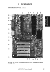
Models without ISA will have 5 PCI slots. ASUS K7M User's Manual 13 FEATURES 2.2 Motherboard Parts...continued 1 23 4 5 6 23 22 21 20 19 18 17 16 15 14 13 12 11 10 9 8 7 ISA model. ISA slots are optional at the time of purchase. FEATURES Motherboard Parts 2. 2.
Models without ISA will have 5 PCI slots. ASUS K7M User's Manual 13 FEATURES 2.2 Motherboard Parts...continued 1 23 4 5 6 23 22 21 20 19 18 17 16 15 14 13 12 11 10 9 8 7 ISA model. ISA slots are optional at the time of purchase. FEATURES Motherboard Parts 2. 2.
K7M User Manual
Page 14
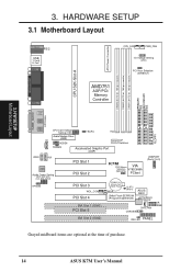
HARDWARE SETUP 3.1 Motherboard Layout PARALLEL PORT ATX Power Connector DIMM3 (64/72 bit, ...Graphic Port (AGP) VIDEO AUX Audio Codec Audio Codec Setting (SPK, AUD_EN1, AUD_EN2, ADN#) HPHONE PCI Slot 1 PCI Slot 2 K7M PS/2 Mouse VIA Selection VT82C686A (MSDATA) PCIset USBPORT (Ports 2 & 3) PCI Slot 3 WOL_CON PCI Slot 4 ISA Slot 1 (...) 2Mbit Flash EEPROM (Programmable BIOS) ASUS ASIC Hardware Monitor CHA_FAN CHASSIS IR SMB ISA Slot 2 (ISA2) IDE LED PANEL Grayed midboard items are optional at the time of purchase. 14 ASUS K7M User's Manual H/W SETUP Motherboard Layout 3. 3.
HARDWARE SETUP 3.1 Motherboard Layout PARALLEL PORT ATX Power Connector DIMM3 (64/72 bit, ...Graphic Port (AGP) VIDEO AUX Audio Codec Audio Codec Setting (SPK, AUD_EN1, AUD_EN2, ADN#) HPHONE PCI Slot 1 PCI Slot 2 K7M PS/2 Mouse VIA Selection VT82C686A (MSDATA) PCIset USBPORT (Ports 2 & 3) PCI Slot 3 WOL_CON PCI Slot 4 ISA Slot 1 (...) 2Mbit Flash EEPROM (Programmable BIOS) ASUS ASIC Hardware Monitor CHA_FAN CHASSIS IR SMB ISA Slot 2 (ISA2) IDE LED PANEL Grayed midboard items are optional at the time of purchase. 14 ASUS K7M User's Manual H/W SETUP Motherboard Layout 3. 3.
K7M User Manual
Page 15
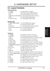
H/W SETUP Layout Contents 3. HARDWARE SETUP 3.2 Layout Contents Motherboard Settings 1) 3VSBSLT p.18 Vaux Setting (+3V/+3VSB) 2) MSDATA p.18 PS/2 Mouse Setting (IRQ12/MSDATA) 3) VIO p.19 I/O Voltage Setting (3.31V/3.4V/3.56V) 4) SPK/AUD_EN1/_EN2/ADN# p....) 16) IR p.41 Serial Infrared Module Connector (5 pins) 17) SMB p.41 SMBus Connector (5-1 pins) 18) CHASSIS p.42 Chassis Intrusion Alarm Lead (4-1 pins) 19) ATXPWR p.42 ATX Power Supply Connector (20 pins) 20) USBPORT p.43 USB Connector Set (10-1 pins) ASUS K7M User's Manual 15 3.
H/W SETUP Layout Contents 3. HARDWARE SETUP 3.2 Layout Contents Motherboard Settings 1) 3VSBSLT p.18 Vaux Setting (+3V/+3VSB) 2) MSDATA p.18 PS/2 Mouse Setting (IRQ12/MSDATA) 3) VIO p.19 I/O Voltage Setting (3.31V/3.4V/3.56V) 4) SPK/AUD_EN1/_EN2/ADN# p....) 16) IR p.41 Serial Infrared Module Connector (5 pins) 17) SMB p.41 SMBus Connector (5-1 pins) 18) CHASSIS p.42 Chassis Intrusion Alarm Lead (4-1 pins) 19) ATXPWR p.42 ATX Power Supply Connector (20 pins) 20) USBPORT p.43 USB Connector Set (10-1 pins) ASUS K7M User's Manual 15 3.
K7M User Manual
Page 17
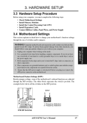
... block represents the switch's position. Frequency Selection 2. Frequency Selection ASUS K7M User's Manual 17 Ensure that came with the component whenever the components are adjusted through the use of your computer. 1. Computer motherboards and expansion cards contain very delicate Integrated Circuit (IC) chips....object, such as the power supply case. 3. DSW1 01 01 01 ON 12 K7M K7M DIP Switches 1. Place components on a grounded antistatic pad or on the bag that the ATX power supply is switched off before handling computer components. OFF ON 3. HARDWARE SETUP 3.3...
... block represents the switch's position. Frequency Selection 2. Frequency Selection ASUS K7M User's Manual 17 Ensure that came with the component whenever the components are adjusted through the use of your computer. 1. Computer motherboards and expansion cards contain very delicate Integrated Circuit (IC) chips....object, such as the power supply case. 3. DSW1 01 01 01 ON 12 K7M K7M DIP Switches 1. Place components on a grounded antistatic pad or on the bag that the ATX power supply is switched off before handling computer components. OFF ON 3. HARDWARE SETUP 3.3...
K7M User Manual
Page 18
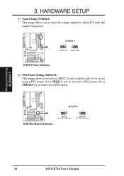
... if you want to use a PS/2 mouse. Set to IRQ12 if you do not have a PS/2 mouse. H/W SETUP Motherboard Settings 18 ASUS K7M User's Manual MSDATA K7M 123 123 IRQ12 (w/o PS/2 Mouse) MSDATA (w/ PS/2 Mouse) K7M PS/2 Mouse Selection 3. 01 01 01 01 01 01 3. Set to MSDATA if you are not using a PS/2 mouse...
... if you want to use a PS/2 mouse. Set to IRQ12 if you do not have a PS/2 mouse. H/W SETUP Motherboard Settings 18 ASUS K7M User's Manual MSDATA K7M 123 123 IRQ12 (w/o PS/2 Mouse) MSDATA (w/ PS/2 Mouse) K7M PS/2 Mouse Selection 3. 01 01 01 01 01 01 3. Set to MSDATA if you are not using a PS/2 mouse...

K7M User Manual
Page 19
A higher voltage is strongly recommended that you leave this section). H/W SETUP Motherboard Settings 01 01 01 01 01 01 K7M I /O Setting (VIO) This jumper allows you are using an ISA or PCI audio expansion... [3-4] 123 4 VIO 123 4 123 4 3.31 Volt 3.4 Volt 3.56 Volt K7M 3. Setting Enable AUDIO CODEC [1-2] [1-2] [1-2] [1-2] Disable [2-3] [2-3] [2-3] [2-3] Enable Onboard Audio Codec Disable Onboard Audio Codec SPK AUD_EN2 SPK AUD_EN2 3 3 K7M 2 2 1 1 AUD_EN1 ADN# AUD_EN1 ADN# K7M Audio Codec Setting ASUS K7M User's Manual 19 The default voltage is set at 3.4V.
A higher voltage is strongly recommended that you leave this section). H/W SETUP Motherboard Settings 01 01 01 01 01 01 K7M I /O Setting (VIO) This jumper allows you are using an ISA or PCI audio expansion... [3-4] 123 4 VIO 123 4 123 4 3.31 Volt 3.4 Volt 3.56 Volt K7M 3. Setting Enable AUDIO CODEC [1-2] [1-2] [1-2] [1-2] Disable [2-3] [2-3] [2-3] [2-3] Enable Onboard Audio Codec Disable Onboard Audio Codec SPK AUD_EN2 SPK AUD_EN2 3 3 K7M 2 2 1 1 AUD_EN1 ADN# AUD_EN1 ADN# K7M Audio Codec Setting ASUS K7M User's Manual 19 The default voltage is set at 3.4V.
K7M User Manual
Page 20
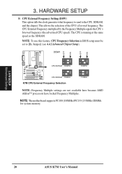
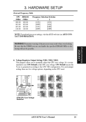
The CPU is running at the same speed as the SDRAM. NOTE: The motherboard supports PC100 (100MHz)/PC133 (133MHz) DIMMs for system memory. 3. 3. HARDWARE SETUP 5) CPU External Frequency Setting (DSW) This option tells the clock generator what ...ON 12 ON 12 ON CPU/SDRAM 100MHz K7M ® CPU/SDRAM 105MHz K7M CPU External Frequency Selection 12 ON 12 103MHz 110MHz NOTE: Frequency Multiple settings are not available here because AMD Athlon™ processors have locked Frequency Multiples. H/W SETUP Motherboard Settings 20 ASUS K7M User's Manual This allows the selection of ...
The CPU is running at the same speed as the SDRAM. NOTE: The motherboard supports PC100 (100MHz)/PC133 (133MHz) DIMMs for system memory. 3. 3. HARDWARE SETUP 5) CPU External Frequency Setting (DSW) This option tells the clock generator what ...ON 12 ON 12 ON CPU/SDRAM 100MHz K7M ® CPU/SDRAM 105MHz K7M CPU External Frequency Selection 12 ON 12 103MHz 110MHz NOTE: Frequency Multiple settings are not available here because AMD Athlon™ processors have locked Frequency Multiples. H/W SETUP Motherboard Settings 20 ASUS K7M User's Manual This allows the selection of ...
K7M User Manual
Page 21
... used. H/W SETUP Motherboard Settings 3. Premature wearing of the processor may result when overclocking. K7M K7M CPU Core Voltage Selection 01 01 01 1234 VID1 VID2 VID3 2/2.05Volts 1234 VID1 VID2 VID3 1.7/1.75Volts 1234 VID1 VID2 VID3 1.4/1.45Volts 1234 1.9/1.95Volts 1234 1.6/1.65Volts 1234 1.3/1.35olts 1234 1.8/1.85Volts 1234 1.5/1.55Volts 1234 CPU Default ASUS K7M User's Manual 21...
... used. H/W SETUP Motherboard Settings 3. Premature wearing of the processor may result when overclocking. K7M K7M CPU Core Voltage Selection 01 01 01 1234 VID1 VID2 VID3 2/2.05Volts 1234 VID1 VID2 VID3 1.7/1.75Volts 1234 VID1 VID2 VID3 1.4/1.45Volts 1234 1.9/1.95Volts 1234 1.6/1.65Volts 1234 1.3/1.35olts 1234 1.8/1.85Volts 1234 1.5/1.55Volts 1234 CPU Default ASUS K7M User's Manual 21...
K7M User Manual
Page 22
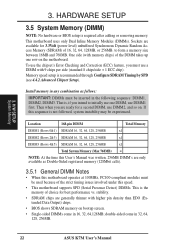
...(see 4.4.2 Advanced Chipset Setup). Install memory in any combination as Double-Sided registered memory (128Mbit cells). 3.5.1 General DIMM Notes • When this motherboard operates at 100MHz, PC100-compliant modules must use a DIMM with memory chips) of 16, 32, 64, 128MB, or 256MB. Location 168-pin ...use DIMM2, and so on. to initially use one row on bootup screen. • Single-sided DIMMs come in 32, 64, 128, 256MB. 22 ASUS K7M User's Manual One side (with 9 chips per side (standard 8 chips/side + 1 ECC chip). Memory speed setup is required after adding or removing ...
...(see 4.4.2 Advanced Chipset Setup). Install memory in any combination as Double-Sided registered memory (128Mbit cells). 3.5.1 General DIMM Notes • When this motherboard operates at 100MHz, PC100-compliant modules must use a DIMM with memory chips) of 16, 32, 64, 128MB, or 256MB. Location 168-pin ...use DIMM2, and so on. to initially use one row on bootup screen. • Single-sided DIMMs come in 32, 64, 128, 256MB. 22 ASUS K7M User's Manual One side (with 9 chips per side (standard 8 chips/side + 1 ECC chip). Memory speed setup is required after adding or removing ...
K7M User Manual
Page 23
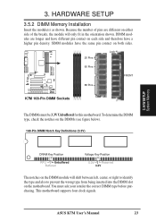
SIMM modules have the same pin contact on the DIMMs (see figure below). 168-Pin DIMM Notch Key Definitions (3.3V) 3. This motherboard supports four clock signals. ASUS K7M User's Manual 23 Because the number of the breaks, the module will shift between left, center, or right to identify the type and also... to prevent the wrong type from being inserted into the DIMM slot on the motherboard. To determine the DIMM type, check the ...
SIMM modules have the same pin contact on the DIMMs (see figure below). 168-Pin DIMM Notch Key Definitions (3.3V) 3. This motherboard supports four clock signals. ASUS K7M User's Manual 23 Because the number of the breaks, the module will shift between left, center, or right to identify the type and also... to prevent the wrong type from being inserted into the DIMM slot on the motherboard. To determine the DIMM type, check the ...
K7M User Manual
Page 25
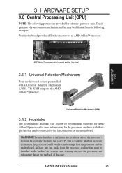
... the processor could overheat and damage both the processor and the motherboard. ASUS K7M User's Manual 25 H/W SETUP CPU AMD Athlon™ processor with heatsink and fan (top view) 3.6.1 Universal Retention Mechanism Your motherboard comes preinstalled with threepin fans that your retention mechanism and fan ...for AMD Athlon™ processors for more information) for the processors are provided for an AMD Athlon™ processor. 3. Your motherboard provides a Slot A connector for reference purposes only. The URM supports the AMD Athlon™ processor. Be sure that there ...
... the processor could overheat and damage both the processor and the motherboard. ASUS K7M User's Manual 25 H/W SETUP CPU AMD Athlon™ processor with heatsink and fan (top view) 3.6.1 Universal Retention Mechanism Your motherboard comes preinstalled with threepin fans that your retention mechanism and fan ...for AMD Athlon™ processors for more information) for the processors are provided for an AMD Athlon™ processor. 3. Your motherboard provides a Slot A connector for reference purposes only. The URM supports the AMD Athlon™ processor. Be sure that there ...
K7M User Manual
Page 27
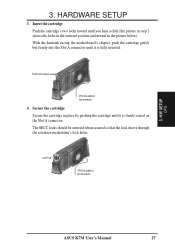
With the heatsink facing the motherboard's chipset, push the cartridge gently but firmly into the Slot A connector until it is firmly seated on the Slot A connector. Push lock inward CPU fan cable to fan connector 3. 3. Lock hole CPU fan cable to fan connector 4. H/W SETUP CPU ASUS K7M User's Manual 27 The SECC locks should...
With the heatsink facing the motherboard's chipset, push the cartridge gently but firmly into the Slot A connector until it is firmly seated on the Slot A connector. Push lock inward CPU fan cable to fan connector 3. 3. Lock hole CPU fan cable to fan connector 4. H/W SETUP CPU ASUS K7M User's Manual 27 The SECC locks should...


