User Manual
Page 3
... 886-2-894-3449 Email: info@asus.com.tw Technical Support: Fax: 886-2-895-9254 BBS: 886-2-896-4667 Email: tsd@asus.com.tw WWW: http://www.asus.com.tw/ Gopher: gopher.asus.com.tw FTP: ftp.asus.com.tw/pub/ASUS ASUS COMPUTER INTERNATIONAL Marketing Info: Address:...asus.com.tw Technical Support: BBS: 1-408-474-0555 Email: tsd-usa@asus.com.tw ASUS COMPUTER GmbH Marketing Info: Address: Harkort Str. 25, 40880 Ratingen, BRD, Germany Telephone: 49-2102-445011 Fax: 49-2102-442066 Email: info-ger@asus.com.tw Technical Support: BBS: 49-2102-448690 Email: tsd-ger@asus.com.tw ASUS HX97...
... 886-2-894-3449 Email: info@asus.com.tw Technical Support: Fax: 886-2-895-9254 BBS: 886-2-896-4667 Email: tsd@asus.com.tw WWW: http://www.asus.com.tw/ Gopher: gopher.asus.com.tw FTP: ftp.asus.com.tw/pub/ASUS ASUS COMPUTER INTERNATIONAL Marketing Info: Address:...asus.com.tw Technical Support: BBS: 1-408-474-0555 Email: tsd-usa@asus.com.tw ASUS COMPUTER GmbH Marketing Info: Address: Harkort Str. 25, 40880 Ratingen, BRD, Germany Telephone: 49-2102-445011 Fax: 49-2102-442066 Email: info-ger@asus.com.tw Technical Support: BBS: 49-2102-448690 Email: tsd-ger@asus.com.tw ASUS HX97...

User Manual
Page 4
...Features Setup 42 Power Management Setup 46 Details of Power Management Setup 46 PNP and PCI Setup 48 Details of the ASUS HX97 Motherboard 10 Installation Steps 12 1. System Memory (SIMM 17 SIMM Memory Installation 18 3. External Connectors 22 Power Connection ... of the ASUS HX97 Motherboard 8 Parts of the ASUS HX97 Motherboard 9 III. Central Processing Unit (CPU 19 4. CONTENTS I. INTRODUCTION 7 How this manual is organized 7 Item Checklist 7 II. Jumpers 12 Jumper Settings 13 Compatible Cyrix CPU Identification 15 2. BIOS SOFTWARE 32 Support Software 32 Flash...
...Features Setup 42 Power Management Setup 46 Details of Power Management Setup 46 PNP and PCI Setup 48 Details of the ASUS HX97 Motherboard 10 Installation Steps 12 1. System Memory (SIMM 17 SIMM Memory Installation 18 3. External Connectors 22 Power Connection ... of the ASUS HX97 Motherboard 8 Parts of the ASUS HX97 Motherboard 9 III. Central Processing Unit (CPU 19 4. CONTENTS I. INTRODUCTION 7 How this manual is organized 7 Item Checklist 7 II. Jumpers 12 Jumper Settings 13 Compatible Cyrix CPU Identification 15 2. BIOS SOFTWARE 32 Support Software 32 Flash...
User Manual
Page 5
... Windows 95 Software I DOS & Windows 3.x Software I ASUS HX97 User's Manual 5 ASUS PCI-SC200 SCSI Card 57 SCSI BIOS and Drivers 57 The ASUS PCI-SC200 SCSI Interface Card 58 Setting Up the ASUS PCI-SC200 58 Setting the INT Assignment 59 Terminator Settings 59 SCSI ID Numbers 60 VII. SUPPORT SOFTWARE 54 Desktop Management Interface (DMI...
... Windows 95 Software I DOS & Windows 3.x Software I ASUS HX97 User's Manual 5 ASUS PCI-SC200 SCSI Card 57 SCSI BIOS and Drivers 57 The ASUS PCI-SC200 SCSI Interface Card 58 Setting Up the ASUS PCI-SC200 58 Setting the INT Assignment 59 Terminator Settings 59 SCSI ID Numbers 60 VII. SUPPORT SOFTWARE 54 Desktop Management Interface (DMI...

User Manual
Page 7
...check that your retailer. √ The ASUS HX97 motherboard √ 2 serial port ribbon cables attached to a mounting bracket √ 1 parallel ribbon cable with mounting bracket √ 1 IDE ribbon cable √ 1 floppy ribbon cable √ ASUS HX97 Support Drivers: • Flash Memory Writer utility... to update the FLASH BIOS • Desktop Management Interface (DMI) utility • Audio drivers and utilities (included with ASUS I-A16C Audio bundle) • Readme files for ...
...check that your retailer. √ The ASUS HX97 motherboard √ 2 serial port ribbon cables attached to a mounting bracket √ 1 parallel ribbon cable with mounting bracket √ 1 IDE ribbon cable √ 1 floppy ribbon cable √ ASUS HX97 Support Drivers: • Flash Memory Writer utility... to update the FLASH BIOS • Desktop Management Interface (DMI) utility • Audio drivers and utilities (included with ASUS I-A16C Audio bundle) • Readme files for ...

User Manual
Page 8
.... • Level 2 Cache: 256 or 512KB Pipelined Burst SRAM onboard. • Optional PS/2 Mouse, USB, IrDA Connector: Supports an optional cable and bracket set to mount the connectors to support optional ASUS SCSI controller cards. 8 ASUS HX97 User's Manual This motherboard: • Intel Chipset: Features Intel's 430HX PCIset with I /O: Provides two high-speed UART compatible...
.... • Level 2 Cache: 256 or 512KB Pipelined Burst SRAM onboard. • Optional PS/2 Mouse, USB, IrDA Connector: Supports an optional cable and bracket set to mount the connectors to support optional ASUS SCSI controller cards. 8 ASUS HX97 User's Manual This motherboard: • Intel Chipset: Features Intel's 430HX PCIset with I /O: Provides two high-speed UART compatible...
User Manual
Page 15
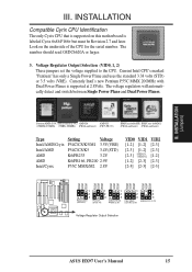
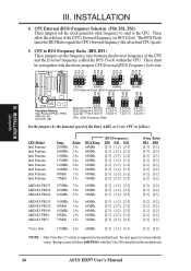
...P55C MMC/ AMDK6-233 (3.2V) PR200 (2.9V) Cyrix M2 (2.8V) Voltage Regulator Output Selection ASUS HX97 User's Manual 15 III. INSTALLATION Compatible Cyrix CPU Identification The only Cyrix CPU that is supported on the underside of the CPU for the serial number. Currently Intel's new Pentium P55C MMX... 200MHz with Dual Power Planes is labeled Cyrix 6x86 P166+ but must be Revision 2.7 and later. Look on this motherboard is supported at 2.8Volts. Current Intel CPU's marked "Pentium" has only a Single Power Plane and uses the standard 3.38 volts (STD) or 3.5 volts ...
...P55C MMC/ AMDK6-233 (3.2V) PR200 (2.9V) Cyrix M2 (2.8V) Voltage Regulator Output Selection ASUS HX97 User's Manual 15 III. INSTALLATION Compatible Cyrix CPU Identification The only Cyrix CPU that is supported on the underside of the CPU for the serial number. Currently Intel's new Pentium P55C MMX... 200MHz with Dual Power Planes is labeled Cyrix 6x86 P166+ but must be Revision 2.7 and later. Look on this motherboard is supported at 2.8Volts. Current Intel CPU's marked "Pentium" has only a Single Power Plane and uses the standard 3.38 volts (STD) or 3.5 volts ...
User Manual
Page 16
...[2-3] [2-3] [2-3] [2-3] [1-2] [2-3] [1-2] [2-3] [1-2] [1-2] [1-2] [1-2] [1-2] [1-2] [1-2] [1-2] [2-3] [1-2] [2-3] [2-3] [1-2] [1-2] [1-2] [1-2] [1-2] [1-2] [1-2] [1-2] [1-2] [1-2] *Cyrix 166+ 133MHz 2.0x 66MHz [2-3] [1-2] [2-3] [1-2] [2-3] *NOTE: Only Cyrix Rev 2.7 or later is supported on this motherboard. INSTALLATION (Jumpers) Complete Names: Intel Pentium P54C, P55C AMD K5, K6 Cyrix M1, M2 P54C/K5 1.5x(3/2) 2.0x(2/1) P55C/K6/M2 3.5X(7/2) 2....) These jumpers set together with the Cyrix 166+ installed on this motherboard. 16 ASUS HX97 User's Manual INSTALLATION 4. III.
...[2-3] [2-3] [2-3] [2-3] [1-2] [2-3] [1-2] [2-3] [1-2] [1-2] [1-2] [1-2] [1-2] [1-2] [1-2] [1-2] [2-3] [1-2] [2-3] [2-3] [1-2] [1-2] [1-2] [1-2] [1-2] [1-2] [1-2] [1-2] [1-2] [1-2] *Cyrix 166+ 133MHz 2.0x 66MHz [2-3] [1-2] [2-3] [1-2] [2-3] *NOTE: Only Cyrix Rev 2.7 or later is supported on this motherboard. INSTALLATION (Jumpers) Complete Names: Intel Pentium P54C, P55C AMD K5, K6 Cyrix M1, M2 P54C/K5 1.5x(3/2) 2.0x(2/1) P55C/K6/M2 3.5X(7/2) 2....) These jumpers set together with the Cyrix 166+ installed on this motherboard. 16 ASUS HX97 User's Manual INSTALLATION 4. III.
User Manual
Page 17
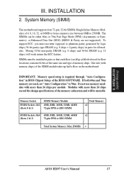
... 3&4 4MB, 8MB, 16MB, 32MB, 64MB (Rows 2 & 3) 72-pin FPM or EDO SIMM Total Memory x2 x2 Total System Memory (Max 256MB) = III. To support ECC, you must be installed in pairs so that each Row (see Map of Motherboard for all modules. If both 60ns and 70ns memory are...Fast Page Mode (FPM) (Asymmetric or Symmetric), or Enhanced Data Out (EDO) (BEDO & Parity are used, set "Auto Configuration" to 256MB. INSTALLATION (System Memory) ASUS HX97 User's Manual 17 The SIMMs can be unstable. SIMMs must use memory modules with memory chips) of 4, 8, 16, 32, or 64MB to form a memory size...
... 3&4 4MB, 8MB, 16MB, 32MB, 64MB (Rows 2 & 3) 72-pin FPM or EDO SIMM Total Memory x2 x2 Total System Memory (Max 256MB) = III. To support ECC, you must be installed in pairs so that each Row (see Map of Motherboard for all modules. If both 60ns and 70ns memory are...Fast Page Mode (FPM) (Asymmetric or Symmetric), or Enhanced Data Out (EDO) (BEDO & Parity are used, set "Auto Configuration" to 256MB. INSTALLATION (System Memory) ASUS HX97 User's Manual 17 The SIMMs can be unstable. SIMMs must use memory modules with memory chips) of 4, 8, 16, 32, or 64MB to form a memory size...
User Manual
Page 18
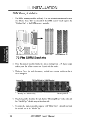
... socket. 3. The SIMM memory modules will only fit in SIMM Socket Safety Tab (This Side Only) Mounting Hole 4. Support Clip 72 Pin DRAM in one orientation as shown because of the "Metal Clips". 18 ASUS HX97 User's Manual INSTALLATION SIMM Memory Installation 1. With your finger tips, rock the memory module into place. III.
... socket. 3. The SIMM memory modules will only fit in SIMM Socket Safety Tab (This Side Only) Mounting Hole 4. Support Clip 72 Pin DRAM in one orientation as shown because of the "Metal Clips". 18 ASUS HX97 User's Manual INSTALLATION SIMM Memory Installation 1. With your finger tips, rock the memory module into place. III.
User Manual
Page 22
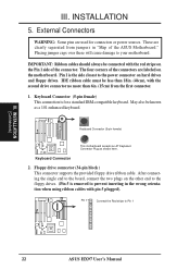
External Connectors WARNING: Some pins are clearly separated from the first connector. 1. Floppy drive connector (34-pin block ) This connector supports the provided floppy drive ribbon cable. The four corners of the connectors are labeled on the other end to the floppy drives. (Pin 5...and floppy drives. Pin 1 Connect the Red stripe to your motherboard. R R III. Placing jumper caps over these will cause damage to Pin 1 22 ASUS HX97 User's Manual Keyboard Connector (5-pin female) This connection is the side closest to the board, connect the two plugs on the motherboard.
External Connectors WARNING: Some pins are clearly separated from the first connector. 1. Floppy drive connector (34-pin block ) This connector supports the provided floppy drive ribbon cable. The four corners of the connectors are labeled on the other end to the floppy drives. (Pin 5...and floppy drives. Pin 1 Connect the Red stripe to your motherboard. R R III. Placing jumper caps over these will cause damage to Pin 1 22 ASUS HX97 User's Manual Keyboard Connector (5-pin female) This connection is the side closest to the board, connect the two plugs on the motherboard.

User Manual
Page 23
... connectors and mount them directly to the case to a free expansion slot opening . Serial Port COM1 and COM2 Connectors (Two 10-pin blocks) These connectors support the provided serial port ribbon cables with pin 26 plugged). Parallel Printer Connector (26 Pin Block) Connection for a parallel printer cable. The two serial ports... connectors to save expansion slot space. See "Onboard Serial Port" in Chipset Features Setup. (Pin 10 is removed to the serial port. Serial Port Connectors ASUS HX97 User's Manual 23
... connectors and mount them directly to the case to a free expansion slot opening . Serial Port COM1 and COM2 Connectors (Two 10-pin blocks) These connectors support the provided serial port ribbon cables with pin 26 plugged). Parallel Printer Connector (26 Pin Block) Connection for a parallel printer cable. The two serial ports... connectors to save expansion slot space. See "Onboard Serial Port" in Chipset Features Setup. (Pin 10 is removed to the serial port. Serial Port Connectors ASUS HX97 User's Manual 23

User Manual
Page 24
...III. Pin 1 Connect the Red stripe to the cabinet's IDE activity LED. Primary / Secondary IDE connectors (Two 40-pin Block) These connectors support the provided IDE hard disk ribbon cable. TIP: You may install one ribbon cable on the primary IDE connector and another on the secondary IDE...power to Pin 1 IDE (Hard Drive) Connectors Secondary IDE Connector Primary IDE Connector 6. IDE (Hard Drive) LED Hard Drive LED Lead 24 ASUS HX97 User's Manual If you install two hard disks, you must configure the second drive to be both Masters using ribbon cables with pin 20 plugged)....
...III. Pin 1 Connect the Red stripe to the cabinet's IDE activity LED. Primary / Secondary IDE connectors (Two 40-pin Block) These connectors support the provided IDE hard disk ribbon cable. TIP: You may install one ribbon cable on the primary IDE connector and another on the secondary IDE...power to Pin 1 IDE (Hard Drive) Connectors Secondary IDE Connector Primary IDE Connector 6. IDE (Hard Drive) LED Hard Drive LED Lead 24 ASUS HX97 User's Manual If you install two hard disks, you must configure the second drive to be both Masters using ribbon cables with pin 20 plugged)....

User Manual
Page 25
... an optional Infrared module to the motherboard. The external connector set . See "Second Infrared" connector for use IRQ12. Infrared Module Connector ASUS HX97 User's Manual 25 III. This module mounts to a small opening on the Back View and connect a ribbon cable from the module.... INSTALLATION 7. The system will direct IRQ12 to select whether UART2 is a second connector that support this feature. Use the five pins as shown on system cases that supports the optional wireless transmitting and receiving infrared module. See "PS/2 Mouse Control" in BIOS Features...
... an optional Infrared module to the motherboard. The external connector set . See "Second Infrared" connector for use IRQ12. Infrared Module Connector ASUS HX97 User's Manual 25 III. This module mounts to a small opening on the Back View and connect a ribbon cable from the module.... INSTALLATION 7. The system will direct IRQ12 to select whether UART2 is a second connector that support this feature. Use the five pins as shown on system cases that supports the optional wireless transmitting and receiving infrared module. See "PS/2 Mouse Control" in BIOS Features...
User Manual
Page 28
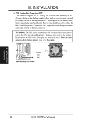
...on the fan manufacturer, the wiring and plug may occur to the motherboard and/or the CPU fan if these pins. INSTALLATION (Connectors) 28 ASUS HX97 User's Manual Orientate the fan so that the heat sink fins allow airflow to the board taking into consideration the polarity of the this connector.... used. Connect the fan's plug to go across the CPU and onboard heatsinks. Damage may be ground. CPU Cooling Fan Connector (FAN) This connector supports a CPU cooling fan of the expansion slots. III. FANPWR Air Flow GND +12V GND CPU Cooling Fan Power Air Flow R III. The red ...
...on the fan manufacturer, the wiring and plug may occur to the motherboard and/or the CPU fan if these pins. INSTALLATION (Connectors) 28 ASUS HX97 User's Manual Orientate the fan so that the heat sink fins allow airflow to the board taking into consideration the polarity of the this connector.... used. Connect the fan's plug to go across the CPU and onboard heatsinks. Damage may be ground. CPU Cooling Fan Connector (FAN) This connector supports a CPU cooling fan of the expansion slots. III. FANPWR Air Flow GND +12V GND CPU Cooling Fan Power Air Flow R III. The red ...
User Manual
Page 32
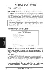
...as your screen during bootup. BIOS SOFTWARE Support Software FILELIST.TXT - Save the motherboard's BIOS file to the programmable flash ROM chip on the upper left-hand corner of the Flash memory chip onto a diskette. BIOS (Flash Memory Writer) 32 ASUS HX97 User's Manual This is shown after "Flash... the PFLASH.EXE and the BIOS to reinstall it. IV. Main Menu 1. NOTE: A binary BIOS file is not programmable or not supported with the support software. Update BIOS Main Block From File 3. PFLASH.EXE - To determine the BIOS version, check the last four numbers of the code...
...as your screen during bootup. BIOS SOFTWARE Support Software FILELIST.TXT - Save the motherboard's BIOS file to the programmable flash ROM chip on the upper left-hand corner of the Flash memory chip onto a diskette. BIOS (Flash Memory Writer) 32 ASUS HX97 User's Manual This is shown after "Flash... the PFLASH.EXE and the BIOS to reinstall it. IV. Main Menu 1. NOTE: A binary BIOS file is not programmable or not supported with the support software. Update BIOS Main Block From File 3. PFLASH.EXE - To determine the BIOS version, check the last four numbers of the code...
User Manual
Page 34
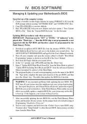
... second screen prompting you saved to File." IV. If "unknown" is displayed after "Flash type --," then this ROM chip is not programmable or not supported with the PnP BIOS and therefore cannot be "SST" or "INTEL." Boot from booting up . Enter the "Current BIOS Revision:" for details. 2. Just...to Enable "Boot Block Programming" jumper as shown in the complete file name and extension of the Main Menu. 6. BIOS (Flash Memory Writer) 34 ASUS HX97 User's Manual Enter 2 "Update BIOS Main Block From File" from the Main Menu or option 2 "Update BIOS Including Boot Block and ESCD" ...
... second screen prompting you saved to File." IV. If "unknown" is displayed after "Flash type --," then this ROM chip is not programmable or not supported with the PnP BIOS and therefore cannot be "SST" or "INTEL." Boot from booting up . Enter the "Current BIOS Revision:" for details. 2. Just...to Enable "Boot Block Programming" jumper as shown in the complete file name and extension of the Main Menu. 6. BIOS (Flash Memory Writer) 34 ASUS HX97 User's Manual Enter 2 "Update BIOS Main Block From File" from the Main Menu or option 2 "Update BIOS Including Boot Block and ESCD" ...
User Manual
Page 35
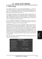
... message, you invoke Setup, the CMOS SETUP UTILITY main program screen will continue with the opportunity to call up Setup. BIOS (BIOS Setup) ASUS HX97 User's Manual 35 If your system using this utility. in this program. If you from calling up the Setup utility. If you are released... can also restart by pushing the Reset button on the system case. When you will need to run this section. BIOS Setup The motherboard supports two programmable Flash ROM chips: 5 Volt and 12 Volt. IV. If you still need to configure your motherboard came in a computer system...
... message, you invoke Setup, the CMOS SETUP UTILITY main program screen will continue with the opportunity to call up Setup. BIOS (BIOS Setup) ASUS HX97 User's Manual 35 If your system using this utility. in this program. If you from calling up the Setup utility. If you are released... can also restart by pushing the Reset button on the system case. When you will need to run this section. BIOS Setup The motherboard supports two programmable Flash ROM chips: 5 Volt and 12 Volt. IV. If you still need to configure your motherboard came in a computer system...

User Manual
Page 37
... up /page down or +/ - keys to the configuration you can bypass the date and time prompts by any the BIOS. Each channel can support up /page down or +/- For IDE hard disk drive setup, you specify. IV. The onboard PCI IDE connectors provide Primary and Secondary channels... supported by creating an AUTOEXEC.BAT file. the first of sectors) and MODE. The entries for hour, minute and second are : Month: (1 to 12), Day: (1 to 31), Year: (up to 2099) Time To set the current time. The documentation that comes with your system. BIOS (Standard CMOS) ASUS HX97 User...
... up /page down or +/ - keys to the configuration you can bypass the date and time prompts by any the BIOS. Each channel can support up /page down or +/- For IDE hard disk drive setup, you specify. IV. The onboard PCI IDE connectors provide Primary and Secondary channels... supported by creating an AUTOEXEC.BAT file. the first of sectors) and MODE. The entries for hour, minute and second are : Month: (1 to 12), Day: (1 to 31), Year: (up to 2099) Time To set the current time. The documentation that comes with your system. BIOS (Standard CMOS) ASUS HX97 User...

User Manual
Page 38
...25 in.; 720KB, 3.5 in.; 1.44MB, 3.5 in.; 2.88MB, 3.5 in parenthesis next to allow you are : EGA/VGA, Mono (for drives over 528MB that support Logical Block Addressing (LBA) to each field: Primary Master, Primary Slave, Secondary Master, and Secondary Slave, you must be partitioned (such as described above by...read from All Errors, No Errors, All, But Keyboard, All, But Diskette, and All, But Disk/Key. BIOS (Standard CMOS) 38 ASUS HX97 User's Manual Auto detection of drive can only be used with FDISK) and then formatted before data can be ignored for a particular drive, ...
...25 in.; 720KB, 3.5 in.; 1.44MB, 3.5 in.; 2.88MB, 3.5 in parenthesis next to allow you are : EGA/VGA, Mono (for drives over 528MB that support Logical Block Addressing (LBA) to each field: Primary Master, Primary Slave, Secondary Master, and Secondary Slave, you must be partitioned (such as described above by...read from All Errors, No Errors, All, But Keyboard, All, But Diskette, and All, But Disk/Key. BIOS (Standard CMOS) 38 ASUS HX97 User's Manual Auto detection of drive can only be used with FDISK) and then formatted before data can be ignored for a particular drive, ...

User Manual
Page 44
...or Disable both a master and a slave making four IDE devices possible. Onboard PCI IDE Enable (Both) You can support up to support the COM2 serial port connector. Because each port. Onboard Parallel Port (378H/IRQ7) This field sets the address of...three parallel ports as long as there are no conflict in a two-way mode. The PC can select to support the infrared module connector on the motherboard. IV. See section III of the baseboard manual for systems with a ...enabled, this field is no conflicts for these to ensure the optimal performance. 44 ASUS HX97 User's Manual
...or Disable both a master and a slave making four IDE devices possible. Onboard PCI IDE Enable (Both) You can support up to support the COM2 serial port connector. Because each port. Onboard Parallel Port (378H/IRQ7) This field sets the address of...three parallel ports as long as there are no conflict in a two-way mode. The PC can select to support the infrared module connector on the motherboard. IV. See section III of the baseboard manual for systems with a ...enabled, this field is no conflicts for these to ensure the optimal performance. 44 ASUS HX97 User's Manual


