
User Manual
Page 1
F1A75-M PRO Motherboard
F1A75-M PRO Motherboard

User Manual
Page 3
DIGI+ VRM 1-2 1.3.3 ASUS Digital Power Design 1-3 1.4 Before you proceed 1-6 1.5 Motherboard overview 1-7 1.5.1 Placement direction 1-7 1.5.2 Screw holes 1-7 1.5.3 Motherboard layout 1-8 1.5.4 Layout contents 1-8 1.6 Accelerated Processing Unit (APU 1-9 1.6.1 Installing the APU 1-9 1.6.2 Installing the ...Internal connectors 1-19 iii Contents Notices...vi Safety information vii About this guide viii F1A75-M PRO specifications summary ix Chapter 1: Product introduction 1.1 Welcome 1-1 1.2 Package contents 1-1 1.3 Special features 1-1 1.3.1 Product highlights 1-1 1.3.2 Dual Intelligent...
DIGI+ VRM 1-2 1.3.3 ASUS Digital Power Design 1-3 1.4 Before you proceed 1-6 1.5 Motherboard overview 1-7 1.5.1 Placement direction 1-7 1.5.2 Screw holes 1-7 1.5.3 Motherboard layout 1-8 1.5.4 Layout contents 1-8 1.6 Accelerated Processing Unit (APU 1-9 1.6.1 Installing the APU 1-9 1.6.2 Installing the ...Internal connectors 1-19 iii Contents Notices...vi Safety information vii About this guide viii F1A75-M PRO specifications summary ix Chapter 1: Product introduction 1.1 Welcome 1-1 1.2 Package contents 1-1 1.3 Special features 1-1 1.3.1 Product highlights 1-1 1.3.2 Dual Intelligent...

User Manual
Page 13
..., making it , check the items in your package with the list below. 1.2 Package contents Check your motherboard package for buying an ASUS® F1A75-M PRO motherboard! series accelerated processor with AMD® Radeon™ HD 6000 series graphics This motherboard supports AMD® A- & E2- This revolutionary APU (Accelerated Processing Unit) combines processing power and advanced DirectX...
..., making it , check the items in your package with the list below. 1.2 Package contents Check your motherboard package for buying an ASUS® F1A75-M PRO motherboard! series accelerated processor with AMD® Radeon™ HD 6000 series graphics This motherboard supports AMD® A- & E2- This revolutionary APU (Accelerated Processing Unit) combines processing power and advanced DirectX...

User Manual
Page 17
... contains the BIOS file. C.P.R. (CPU Parameter Recall) The BIOS C.P.R. ASUS F1A75-M PRO 1-5 ASUS Q-Shield ASUS Q-Shield's special design makes it convenient and easy to install on your motherboard against Electronic Magnetic Interference (EMI). With better electric conductivity, it against static electricity and shields it ideally protects your motherboard. feature automatically restores the CPU default settings when the...
... contains the BIOS file. C.P.R. (CPU Parameter Recall) The BIOS C.P.R. ASUS F1A75-M PRO 1-5 ASUS Q-Shield ASUS Q-Shield's special design makes it convenient and easy to install on your motherboard against Electronic Magnetic Interference (EMI). With better electric conductivity, it against static electricity and shields it ideally protects your motherboard. feature automatically restores the CPU default settings when the...

User Manual
Page 19
Doing so can damage the motherboard. Place this side towards the rear of the chassis as indicated in the correct orientation. F1A75-M PRO ASUS F1A75-M PRO 1-7 DO NOT overtighten the screws! 1.5 Motherboard overview 1.5.1 Placement direction When installing the motherboard, ensure that you place it into the chassis in the image below. 1.5.2 Screw holes Place eight screws into the holes indicated by circles to secure the motherboard to the rear part of the chassis. The edge with external ports goes to the chassis.
Doing so can damage the motherboard. Place this side towards the rear of the chassis as indicated in the correct orientation. F1A75-M PRO ASUS F1A75-M PRO 1-7 DO NOT overtighten the screws! 1.5 Motherboard overview 1.5.1 Placement direction When installing the motherboard, ensure that you place it into the chassis in the image below. 1.5.2 Screw holes Place eight screws into the holes indicated by circles to secure the motherboard to the rear part of the chassis. The edge with external ports goes to the chassis.

User Manual
Page 20
...(10-1 pin AAFP) 1-27 Page 1-27 1-21 1-22 1-16 1-24 1-24 1-21 1-23 1-23 1-8 Chapter 1: Product introduction 1.5.3 Motherboard layout 1 2 13 24.4cm(9.6in) KB_USB3_34 SPDIF_O2 _HDMI ASM 1042 EATX12V DIGI+VRM EPU CPU_FAN SOCKET FM1 DVI_VGA USB3_12 LAN1_USB12 DDR3 DIMM_A1 (64bit... 7 8 9 10 2 EATXPWR CHA_FAN2 24.4cm(9.6in) CHA_FAN1 ICS477D AUDIO RTL 8111E Super I/O PWR_FAN Lithium Cell CMOS Power PCIEX16_1 F1A75-M PRO PCIEX1_1 TPU PCI1 AMD® A75 1 SB_PWR 11 12 SATA6G_2 SATA6G_4 SATA6G_6 SATA6G_1 SATA6G_3 SATA6G_5 ALC 892 AAFP SPDIF_OUT PCIEX16_2 USB78 COM1 USB910...
...(10-1 pin AAFP) 1-27 Page 1-27 1-21 1-22 1-16 1-24 1-24 1-21 1-23 1-23 1-8 Chapter 1: Product introduction 1.5.3 Motherboard layout 1 2 13 24.4cm(9.6in) KB_USB3_34 SPDIF_O2 _HDMI ASM 1042 EATX12V DIGI+VRM EPU CPU_FAN SOCKET FM1 DVI_VGA USB3_12 LAN1_USB12 DDR3 DIMM_A1 (64bit... 7 8 9 10 2 EATXPWR CHA_FAN2 24.4cm(9.6in) CHA_FAN1 ICS477D AUDIO RTL 8111E Super I/O PWR_FAN Lithium Cell CMOS Power PCIEX16_1 F1A75-M PRO PCIEX1_1 TPU PCI1 AMD® A75 1 SB_PWR 11 12 SATA6G_2 SATA6G_4 SATA6G_6 SATA6G_1 SATA6G_3 SATA6G_5 ALC 892 AAFP SPDIF_OUT PCIEX16_2 USB78 COM1 USB910...

User Manual
Page 21
... gold triangle matches the socket corner with AMD® Radeon™ HD 6000 series graphics. Small triangle Gold triangle ASUS F1A75-M PRO 1-9 The APU fits in one correct orientation. F1A75-M PRO F1A75-M PRO processor socket FM1 2. Socket lever Ensure that you use a APU designed for AMD® A- & E2- The...176; angle; Carefully insert the APU into the socket to a 90°-100° angle. 1.6 Accelerated Processing Unit (APU) This motherboard comes with an FM1 socket designed for the FM1 socket. Press the lever sideways to unlock the socket, then lift it fits in completely....
... gold triangle matches the socket corner with AMD® Radeon™ HD 6000 series graphics. Small triangle Gold triangle ASUS F1A75-M PRO 1-9 The APU fits in one correct orientation. F1A75-M PRO F1A75-M PRO processor socket FM1 2. Socket lever Ensure that you use a APU designed for AMD® A- & E2- The...176; angle; Carefully insert the APU into the socket to a 90°-100° angle. 1.6 Accelerated Processing Unit (APU) This motherboard comes with an FM1 socket designed for the FM1 socket. Press the lever sideways to unlock the socket, then lift it fits in completely....

User Manual
Page 22
... plug this connector. CPU FAN PWM CPU FAN IN CPU FAN PWR GND 1-10 Chapter 1: Product introduction The lever clicks on the motherboard. 5. When the APU is locked. 6. CPU_FAN F1A75-M PRO F1A75-M PRO CPU fan connector DO NOT forget to secure the APU. Install a APU heatsink and fan following the instructions that it is in...
... plug this connector. CPU FAN PWM CPU FAN IN CPU FAN PWR GND 1-10 Chapter 1: Product introduction The lever clicks on the motherboard. 5. When the APU is locked. 6. CPU_FAN F1A75-M PRO F1A75-M PRO CPU fan connector DO NOT forget to secure the APU. Install a APU heatsink and fan following the instructions that it is in...

User Manual
Page 23
...instructions in this section do not have to remove the retention module base when installing the CPU or installing other motherboard components. • If you purchased a separate CPU heatsink and fan assembly, ensure that you install the ... fan assembly. 1.6.2 Installing the heatsink and fan Ensure that a Thermal Interface Material is already installed on the motherboard upon purchase. • You do not match the CPU documentation, follow the latter. 2. Place the heatsink ... module base is properly applied to the retention module base. 1 2 3 4 5 ASUS F1A75-M PRO 1-11
...instructions in this section do not have to remove the retention module base when installing the CPU or installing other motherboard components. • If you purchased a separate CPU heatsink and fan assembly, ensure that you install the ... fan assembly. 1.6.2 Installing the heatsink and fan Ensure that a Thermal Interface Material is already installed on the motherboard upon purchase. • You do not match the CPU documentation, follow the latter. 2. Place the heatsink ... module base is properly applied to the retention module base. 1 2 3 4 5 ASUS F1A75-M PRO 1-11

User Manual
Page 24
... has the same physical dimensions as a DDR2 DIMM but is notched differently to plug this connector. 1.7 System memory 1.7.1 Overview This motherboard comes with less power consumption. 3. The figure illustrates the location of the retention bracket to the connector on a DDR2 DIMM socket.... Align the other end of the DDR3 DIMM sockets: DIMM_A1 DIMM_A2 DIMM_B1 DIMM_B2 F1A75-M PRO Channel Channel A Channel B F1A75-M PRO 240-pin DDR3 DIMM sockets Sockets DIMM_A1 and DIMM_A2 DIMM_B1 and DIMM_B2 1-12 Chapter 1: Product introduction DDR3 modules...
... has the same physical dimensions as a DDR2 DIMM but is notched differently to plug this connector. 1.7 System memory 1.7.1 Overview This motherboard comes with less power consumption. 3. The figure illustrates the location of the retention bracket to the connector on a DDR2 DIMM socket.... Align the other end of the DDR3 DIMM sockets: DIMM_A1 DIMM_A2 DIMM_B1 DIMM_B2 F1A75-M PRO Channel Channel A Channel B F1A75-M PRO 240-pin DDR3 DIMM sockets Sockets DIMM_A1 and DIMM_A2 DIMM_B1 and DIMM_B2 1-12 Chapter 1: Product introduction DDR3 modules...

User Manual
Page 25
...CAS latency. Use a 64-bit Windows® OS if you want to install 4GB or more memory on the motherboard. • This motherboard does not support DIMMs made up of the following: - ASUS F1A75-M PRO 1-13 1.7.2 Memory configurations You may install 512MB, 1GB, 2GB, and 4GB unbuffered non-ECC DDR3 DIMMs into ...frequency DIMMs. • Due to the memory address limitation on 32-bit Windows® OS, when you install 4GB or more memory on the motherboard, the actual usable memory for the OS can be about 3GB or less. Any excess memory from a memory module. Under the default state, ...
...CAS latency. Use a 64-bit Windows® OS if you want to install 4GB or more memory on the motherboard. • This motherboard does not support DIMMs made up of the following: - ASUS F1A75-M PRO 1-13 1.7.2 Memory configurations You may install 512MB, 1GB, 2GB, and 4GB unbuffered non-ECC DDR3 DIMMs into ...frequency DIMMs. • Due to the memory address limitation on 32-bit Windows® OS, when you install 4GB or more memory on the motherboard, the actual usable memory for the OS can be about 3GB or less. Any excess memory from a memory module. Under the default state, ...

User Manual
Page 27
... Expansion slots In the future, you may cause you physical injury and damage motherboard components. 1.8.1 Installing an expansion card To install an expansion card: 1. Keep the screw for information on the slot. 5. ASUS F1A75-M PRO 1-15 Turn on shared slots, ensure that the drivers support "Share IRQ"...screw you intend to install expansion cards. Install the software drivers for the card. 2. Remove the system unit cover (if your motherboard is completely seated on BIOS setup. 2. Assign an IRQ to the chassis with it by adjusting the software settings. 1. When using...
... Expansion slots In the future, you may cause you physical injury and damage motherboard components. 1.8.1 Installing an expansion card To install an expansion card: 1. Keep the screw for information on the slot. 5. ASUS F1A75-M PRO 1-15 Turn on shared slots, ensure that the drivers support "Share IRQ"...screw you intend to install expansion cards. Install the software drivers for the card. 2. Remove the system unit cover (if your motherboard is completely seated on BIOS setup. 2. Assign an IRQ to the chassis with it by adjusting the software settings. 1. When using...

User Manual
Page 28
... 2.0 x16_1 slot (blue) for a PCI Express x16 graphics card to get better performance. • We recommend that you to the motherboard connector labeled CHA_FAN1/2 when using multiple graphics cards for better thermal environment. 1.9 Jumpers Clear RTC RAM (CLRTC) This jumper allows you provide... sufficient power when running CrossFireX™ mode. Keep the cap on CLRTC jumper default position. F1A75-M PRO CLRTC 12 23 Normal (Default) F1A75-M PRO Clear RTC RAM Clear RTC To erase the RTC RAM: 1. See page 1-20 for details. • Connect a chassis...
... 2.0 x16_1 slot (blue) for a PCI Express x16 graphics card to get better performance. • We recommend that you to the motherboard connector labeled CHA_FAN1/2 when using multiple graphics cards for better thermal environment. 1.9 Jumpers Clear RTC RAM (CLRTC) This jumper allows you provide... sufficient power when running CrossFireX™ mode. Keep the cap on CLRTC jumper default position. F1A75-M PRO CLRTC 12 23 Normal (Default) F1A75-M PRO Clear RTC RAM Clear RTC To erase the RTC RAM: 1. See page 1-20 for details. • Connect a chassis...

User Manual
Page 31
... Xpert feature. • If you plug the rear chassis fan cable to the fan connectors. ASUS F1A75-M PRO 1-19 Insufficient air flow inside the system may damage the motherboard components. CPU_FAN CPU FAN PWM CPU FAN IN CPU FAN PWR GND CHA_FAN2 CHA FAN PWM CHA_FAN1 CHA FAN IN CHA FAN PWR ...GND GND CHA FAN PWR CHA FAN IN CHA FAN PWM F1A75-M PRO PWR_FAN GND +12V Rotation F1A75-M PRO Fan connectors DO NOT forget to connect the fan cables to the motherboard connector labeled CHA_FAN1/2 for better thermal environment.
... Xpert feature. • If you plug the rear chassis fan cable to the fan connectors. ASUS F1A75-M PRO 1-19 Insufficient air flow inside the system may damage the motherboard components. CPU_FAN CPU FAN PWM CPU FAN IN CPU FAN PWR GND CHA_FAN2 CHA FAN PWM CHA_FAN1 CHA FAN IN CHA FAN PWR ...GND GND CHA FAN PWR CHA FAN IN CHA FAN PWM F1A75-M PRO PWR_FAN GND +12V Rotation F1A75-M PRO Fan connectors DO NOT forget to connect the fan cables to the motherboard connector labeled CHA_FAN1/2 for better thermal environment.

User Manual
Page 35
... (4-1 pin SPDIF_OUT) This connector is for an additional Sony/Philips Digital Interface (S/PDIF) port. +5V SPDIFOUT GND F1A75-M PRO SPDIF_OUT F1A75-M PRO Digital audio connector Ensure that supports either High Definition Audio or AC`97 audio standard. See section 2.5.5 Onboard Devices Configuration...I /O module that the audio device of the motherboard high-definition audio capability. • If you connect a high-definition front panel audio module to this connector to avail of Sound playback is purchased separately. 7. ASUS F1A75-M PRO 1-23 Go to Start > Control Panel > ...
... (4-1 pin SPDIF_OUT) This connector is for an additional Sony/Philips Digital Interface (S/PDIF) port. +5V SPDIFOUT GND F1A75-M PRO SPDIF_OUT F1A75-M PRO Digital audio connector Ensure that supports either High Definition Audio or AC`97 audio standard. See section 2.5.5 Onboard Devices Configuration...I /O module that the audio device of the motherboard high-definition audio capability. • If you connect a high-definition front panel audio module to this connector to avail of Sound playback is purchased separately. 7. ASUS F1A75-M PRO 1-23 Go to Start > Control Panel > ...

User Manual
Page 36
These USB connectors comply with ASUS USB 3.0 header, you can have a front panel USB 3.0 solution. Connect the USB 3.0 bracket cable to this connector, then install the USB 3.0 bracket to...your chassis support customized front panel installation, with USB 2.0 specification that supports up to the USB connectors. USB3_56 F1A75-M PRO F1A75-M PRO USB3.0 Front panel connector The USB 3.0 module is purchased separately. 9. Doing so will damage the motherboard! The USB 2.0 module is purchased separately. 1-24 Chapter 1: Product introduction USB 2.0 connectors (10-1 pin USB34...
These USB connectors comply with ASUS USB 3.0 header, you can have a front panel USB 3.0 solution. Connect the USB 3.0 bracket cable to this connector, then install the USB 3.0 bracket to...your chassis support customized front panel installation, with USB 2.0 specification that supports up to the USB connectors. USB3_56 F1A75-M PRO F1A75-M PRO USB3.0 Front panel connector The USB 3.0 module is purchased separately. 9. Doing so will damage the motherboard! The USB 2.0 module is purchased separately. 1-24 Chapter 1: Product introduction USB 2.0 connectors (10-1 pin USB34...

User Manual
Page 37
MemOK! F1A75-M PRO F1A75-M PRO MemOK! switch • Refer to section 1.12 Onboard LEDs for...ASUS F1A75-M PRO 1-25 switch lights continuously. switch until the DRAM_LED starts blinking to boot and load BIOS default settings. To stop memory tuning, turn off the system and reinstall the DIMM before using the MemOK! function. Replace the DIMMs with the motherboard...ones recommended in the Memory QVL (Qualified Vendors Lists) in this user manual or on the ASUS website at www.asus.com after the whole tuning process, the DRAM_LED lights continuously. function. • The MemOK! ...
MemOK! F1A75-M PRO F1A75-M PRO MemOK! switch • Refer to section 1.12 Onboard LEDs for...ASUS F1A75-M PRO 1-25 switch lights continuously. switch until the DRAM_LED starts blinking to boot and load BIOS default settings. To stop memory tuning, turn off the system and reinstall the DIMM before using the MemOK! function. Replace the DIMMs with the motherboard...ones recommended in the Memory QVL (Qualified Vendors Lists) in this user manual or on the ASUS website at www.asus.com after the whole tuning process, the DRAM_LED lights continuously. function. • The MemOK! ...
User Manual
Page 39
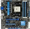
F1A75-M PRO DRAM LED F1A75-M PRO DRAM LED ASUS F1A75-M PRO 1-27 The illustration below shows the location of the onboard LED. This user-friendly design provides an intuitional way to indicate that you should shut down the system and unplug the power cable before removing or plugging in any motherboard component. SB_PWR F1A75-M PRO ON OFF Standby Power Powered Off...
F1A75-M PRO DRAM LED F1A75-M PRO DRAM LED ASUS F1A75-M PRO 1-27 The illustration below shows the location of the onboard LED. This user-friendly design provides an intuitional way to indicate that you should shut down the system and unplug the power cable before removing or plugging in any motherboard component. SB_PWR F1A75-M PRO ON OFF Standby Power Powered Off...

User Manual
Page 1
F1A75-M PRO Motherboard
F1A75-M PRO Motherboard

User Manual
Page 13
series accelerated processors with the list below. 1.2 Package contents Check your motherboard package for buying an ASUS® F1A75-M PRO motherboard! The motherboard delivers a host of ASUS quality motherboards! ASUS F1A75-M PRO 1-1 Before you for the following items. Motherboard Cables Accessories Application DVD Documentations ASUS F1A75-M PRO motherboard 2 x Serial ATA 6.0Gb/s cables 1 x Q-Shield ASUS motherboard Support DVD User Manual If any of the above items is damaged or missing...
series accelerated processors with the list below. 1.2 Package contents Check your motherboard package for buying an ASUS® F1A75-M PRO motherboard! The motherboard delivers a host of ASUS quality motherboards! ASUS F1A75-M PRO 1-1 Before you for the following items. Motherboard Cables Accessories Application DVD Documentations ASUS F1A75-M PRO motherboard 2 x Serial ATA 6.0Gb/s cables 1 x Q-Shield ASUS motherboard Support DVD User Manual If any of the above items is damaged or missing...


