User Manual
Page 10
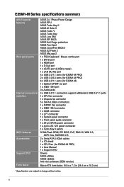
... ASUS EPU ASUS Turbo Key II ASUS AI Suite II ASUS Turbo V ASUS Turbo Key ASUS Low EMI ASUS EFI BIOS ASUS Anti-Surge protection ASUS Fan Xpert ASUS CrashFree BIOS 3 ASUS EZ Flash 2 ASUS MyLogo 2 1 x PS/2 Keyboard / Mouse combo port 1 x DVI-D port 1 x HDMI port 1 x D-Sub port 1 x eSATA port (6.0Gb/s ready) 1 x LAN (RJ-45) port 4 x USB 2.0/1.1 ports (for E35M1-M PRO) 2 x USB 3.0/2.0 ports (for E35M1-M PRO) 6 x USB 2.0/1.1 ports (for E35M1...
... ASUS EPU ASUS Turbo Key II ASUS AI Suite II ASUS Turbo V ASUS Turbo Key ASUS Low EMI ASUS EFI BIOS ASUS Anti-Surge protection ASUS Fan Xpert ASUS CrashFree BIOS 3 ASUS EZ Flash 2 ASUS MyLogo 2 1 x PS/2 Keyboard / Mouse combo port 1 x DVI-D port 1 x HDMI port 1 x D-Sub port 1 x eSATA port (6.0Gb/s ready) 1 x LAN (RJ-45) port 4 x USB 2.0/1.1 ports (for E35M1-M PRO) 2 x USB 3.0/2.0 ports (for E35M1-M PRO) 6 x USB 2.0/1.1 ports (for E35M1...

User Manual
Page 16
... SATA6G_5 RTL 8111E ALC 887 AAFP CLRTC PCIEX1_1 VIA VT6308P Asmedia ASM1083 Super I/O PCI1 E35M1-M PRO Lithium Cell CMOS Power SB_PWR PCI2 SPDIF_OUT IE1394_1 LPT USB1314 USB1112 USB910 USB78 32Mb BIOS COM1 PANEL 8 9 10 16 15 14 13 12 11 1.5.4 Layout contents Connectors.../s connectors (7-pin SATA6G_1~5) 8. Front panel audio connector (10-1 pin AAFP) 1-17 1-13 16. Digital audio connector (4-1 pin SPDIF_OUT) 1-18 1-6 ASUS E35M1-M Series Clear RTC RAM (3-pin CLRTC) Page Connectors/Jumpers/Slots/LED 1-16 9. System panel connector (20-8 pin PANEL) 1-19 1-8 12. Serial ...
... SATA6G_5 RTL 8111E ALC 887 AAFP CLRTC PCIEX1_1 VIA VT6308P Asmedia ASM1083 Super I/O PCI1 E35M1-M PRO Lithium Cell CMOS Power SB_PWR PCI2 SPDIF_OUT IE1394_1 LPT USB1314 USB1112 USB910 USB78 32Mb BIOS COM1 PANEL 8 9 10 16 15 14 13 12 11 1.5.4 Layout contents Connectors.../s connectors (7-pin SATA6G_1~5) 8. Front panel audio connector (10-1 pin AAFP) 1-17 1-13 16. Digital audio connector (4-1 pin SPDIF_OUT) 1-18 1-6 ASUS E35M1-M Series Clear RTC RAM (3-pin CLRTC) Page Connectors/Jumpers/Slots/LED 1-16 9. System panel connector (20-8 pin PANEL) 1-19 1-8 12. Serial ...

User Manual
Page 23
..., time, and system setup parameters by erasing the CMOS RTC RAM data. For system failure due to overclocking. CLRTC 12 23 E35M1-M PRO Normal (Default) Clear RTC E35M1-M PRO Clear RTC RAM To erase the RTC RAM: 1. The onboard button cell battery powers the RAM data in CMOS. After clearing ...onboard battery and move the cap back to re-enter data. Chapter 1: Product introduction 1-13 Shut down the key during the boot process and enter BIOS setup to pins 1-2. 3. Plug the power cord and turn ON the computer. 4. Removing the cap will cause system boot failure! • ...
..., time, and system setup parameters by erasing the CMOS RTC RAM data. For system failure due to overclocking. CLRTC 12 23 E35M1-M PRO Normal (Default) Clear RTC E35M1-M PRO Clear RTC RAM To erase the RTC RAM: 1. The onboard button cell battery powers the RAM data in CMOS. After clearing ...onboard battery and move the cap back to re-enter data. Chapter 1: Product introduction 1-13 Shut down the key during the boot process and enter BIOS setup to pins 1-2. 3. Plug the power cord and turn ON the computer. 4. Removing the cap will cause system boot failure! • ...

User Manual
Page 27
... you want to connect a high-definition front panel audio module to [HD]. CPU_FAN CPU FAN PWM CPU FAN IN CPU FAN PWR GND E35M1-M PRO CHA_FAN GND +12V Rotation E35M1-M PRO fan connectors • Do not forget to connect the fan cables to [HD]. By default, this connector, set to this connector is for... the system may damage the motherboard components. 2. Front panel audio connector (10-1 pin AAFP) This connector is set the Front Panel Type item in the BIOS setup to the fan connectors.
... you want to connect a high-definition front panel audio module to [HD]. CPU_FAN CPU FAN PWM CPU FAN IN CPU FAN PWR GND E35M1-M PRO CHA_FAN GND +12V Rotation E35M1-M PRO fan connectors • Do not forget to connect the fan cables to [HD]. By default, this connector, set to this connector is for... the system may damage the motherboard components. 2. Front panel audio connector (10-1 pin AAFP) This connector is set the Front Panel Type item in the BIOS setup to the fan connectors.

User Manual
Page 28
... chassis. +5V SPDIFOUT GND E35M1-M PRO SPDIF_OUT E35M1-M PRO Digital audio connector The S/PDIF module is for an additional Sony/Philips Digital Interface (S/PDIF) port. See section 2.5.2 SATA Configuration for details. 5. Digital audio connector (4-1 pin SPDIF_OUT) This connector is purchased separately. 1-18 ASUS E35M1-M Series Serial ATA 6.0Gb/s...SATA6G_1 SATA6G_2 GND RSATA_TXP1 RSATA_TXN1 GND RSATA_RXP1 RSATA_RXN1 GND GND RSATA_TXP2 RSATA_TXN2 GND RSATA_RXP2 RSATA_RXN2 GND E35M1-M PRO E35M1-M PRO SATA connectors • These connectors are set the OnChip SATA Type item in the...
... chassis. +5V SPDIFOUT GND E35M1-M PRO SPDIF_OUT E35M1-M PRO Digital audio connector The S/PDIF module is for an additional Sony/Philips Digital Interface (S/PDIF) port. See section 2.5.2 SATA Configuration for details. 5. Digital audio connector (4-1 pin SPDIF_OUT) This connector is purchased separately. 1-18 ASUS E35M1-M Series Serial ATA 6.0Gb/s...SATA6G_1 SATA6G_2 GND RSATA_TXP1 RSATA_TXN1 GND RSATA_RXP1 RSATA_RXN1 GND GND RSATA_TXP2 RSATA_TXN2 GND RSATA_RXP2 RSATA_RXN2 GND E35M1-M PRO E35M1-M PRO SATA connectors • These connectors are set the OnChip SATA Type item in the...
User Manual
Page 32
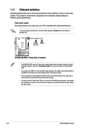
... use the last setting you have made. 1-22 ASUS E35M1-M Series This is ideal for the exact location of the O2LED2 LED. • If you clear the CMOS or load the BIOS setup defaults, the related overclocking items in the BIOS setup program, and enable the Turbo Key II function...the system performance. Refer to section 1.12 Onboard LEDs for overclockers and gamers who continually change the switch setting to enhance system performance. E35M1-M PRO E35M1-M PRO Turbo Key II switch • The O2LED2 LED near the Turbo Key II switch lights when the switch setting is powered off. 1.11...
... use the last setting you have made. 1-22 ASUS E35M1-M Series This is ideal for the exact location of the O2LED2 LED. • If you clear the CMOS or load the BIOS setup defaults, the related overclocking items in the BIOS setup program, and enable the Turbo Key II function...the system performance. Refer to section 1.12 Onboard LEDs for overclockers and gamers who continually change the switch setting to enhance system performance. E35M1-M PRO E35M1-M PRO Turbo Key II switch • The O2LED2 LED near the Turbo Key II switch lights when the switch setting is powered off. 1.11...
User Manual
Page 36
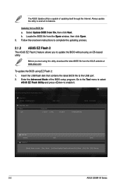
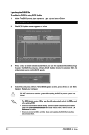
...to the USB port. 2. Updating from file, then click Next. To update the BIOS using an OS‑based utility. Before you to enable it. ASUSTek EZ Flash BIOS ROM Utility V00.75 Flash Info MODEL: E35M1-M PRO File Path: fs0:\ Drive fs0:\ VER: 0027 Folder Info 11/12/10 10:...] Select or Load [Tab] Switch [Up/Down/PageUp/PageDown/Home/End] Move [Esc] Exit [F2] Backup 2-2 ASUS E35M1-M Series Go to the Tool menu to select ASUS EZ Flash Utility and press to update the BIOS without using EZ Flash 2: 1. Enter the Advanced Mode of updating itself through the Internet. Locate the...
...to the USB port. 2. Updating from file, then click Next. To update the BIOS using an OS‑based utility. Before you to enable it. ASUSTek EZ Flash BIOS ROM Utility V00.75 Flash Info MODEL: E35M1-M PRO File Path: fs0:\ Drive fs0:\ VER: 0027 Folder Info 11/12/10 10:...] Select or Load [Tab] Switch [Up/Down/PageUp/PageDown/Home/End] Move [Esc] Exit [F2] Backup 2-2 ASUS E35M1-M Series Go to the Tool menu to select ASUS EZ Flash Utility and press to update the BIOS without using EZ Flash 2: 1. Enter the Advanced Mode of updating itself through the Internet. Locate the...
User Manual
Page 37
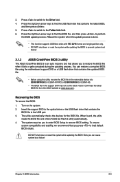
... that contains the latest BIOS, and then press . 5. Download the latest BIOS file from the ASUS website at www.asus.com. To ensure system compatibility and stability, we recommend that contains the updated BIOS file. • Before using this utility, rename the BIOS file in the removable device into E35M1MP.ROM (for E35M1-M PRO) or E35M1M.ROM (for...
... that contains the latest BIOS, and then press . 5. Download the latest BIOS file from the ASUS website at www.asus.com. To ensure system compatibility and stability, we recommend that contains the updated BIOS file. • Before using this utility, rename the BIOS file in the removable device into E35M1MP.ROM (for E35M1-M PRO) or E35M1M.ROM (for...
User Manual
Page 39
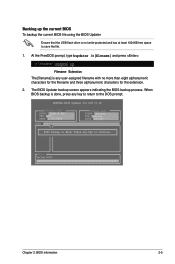
...filename] and press . D:\>bupdater /oOLDBIOS1.rom Filename Extension The [filename] is any key to return to the DOS prompt. When BIOS backup is done, press any user-assigned filename with no more than eight alphanumeric characters for the filename and three alphanumeric characters for ...BOARD: E35M1-M PRO VER: 0027 DATE: 11/12/2010 Update ROM BOARD: Unknown VER: Unknown DATE: Unknown PATH: A:\ BIOS backup is done! Press any key to save the file. 1. ASUSTek BIOS Updater for the extension. 2. Backing up the current BIOS To backup the current BIOS file using the BIOS Updater...
...filename] and press . D:\>bupdater /oOLDBIOS1.rom Filename Extension The [filename] is any key to return to the DOS prompt. When BIOS backup is done, press any user-assigned filename with no more than eight alphanumeric characters for the filename and three alphanumeric characters for ...BOARD: E35M1-M PRO VER: 0027 DATE: 11/12/2010 Update ROM BOARD: Unknown VER: Unknown DATE: Unknown PATH: A:\ BIOS backup is done! Press any key to save the file. 1. ASUSTek BIOS Updater for the extension. 2. Backing up the current BIOS To backup the current BIOS file using the BIOS Updater...
User Manual
Page 40
... • Ensure to connect all SATA hard disk drives after updating BIOS. • Ensure to load the BIOS default settings to the DOS prompt after updating the BIOS file if you have disconnected them. 2-6 ASUS E35M1-M Series Select the Load Optimized Defaults item under the Exit menu. DO...1.04 or later, the utility automatically exits to ensure system compatibility and stability. BIOS Updater checks the selected BIOS file and prompts you sure to section 2.9 Exit menu for DOS V1.18 Current ROM BOARD: E35M1-M PRO VER: 0027 DATE: 11/12/2010 Update ROM BOARD: Unknown VER: Unknown ...
... • Ensure to connect all SATA hard disk drives after updating BIOS. • Ensure to load the BIOS default settings to the DOS prompt after updating the BIOS file if you have disconnected them. 2-6 ASUS E35M1-M Series Select the Load Optimized Defaults item under the Exit menu. DO...1.04 or later, the utility automatically exits to ensure system compatibility and stability. BIOS Updater checks the selected BIOS file and prompts you sure to section 2.9 Exit menu for DOS V1.18 Current ROM BOARD: E35M1-M PRO VER: 0027 DATE: 11/12/2010 Update ROM BOARD: Unknown VER: Unknown ...
User Manual
Page 42
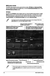
EZ Mode Friday [11/19/2010] E35M1-M PRO BIOS Version : 0027 CPU Type : AMD Engineering Sample Total Memory : 1008 MB (DDR3 1066MHz) Exit/Advanced Mode Build Date : 11/12/2010 Speed : 1000 MHz English ...) button is available only when the boot device is installed to the system. 2-8 ASUS E35M1-M Series Boot Menu(F8) Default(F5) Selects the boot device priority Power Saving mode Loads optimized default Displays the system properties of the BIOS setup program Clicks to decide the boot priority. You can change modes from the...
EZ Mode Friday [11/19/2010] E35M1-M PRO BIOS Version : 0027 CPU Type : AMD Engineering Sample Total Memory : 1008 MB (DDR3 1066MHz) Exit/Advanced Mode Build Date : 11/12/2010 Speed : 1000 MHz English ...) button is available only when the boot device is installed to the system. 2-8 ASUS E35M1-M Series Boot Menu(F8) Default(F5) Selects the boot device priority Power Saving mode Loads optimized default Displays the system properties of the BIOS setup program Clicks to decide the boot priority. You can change modes from the...

User Manual
Page 53
...Audio Device [Enabled] Enables or disables the Azalia High Definition Audio controller. Asmedia USB 3.0 Controller [Enabled] This item only appears on E35M1-M PRO. Configuration options: [Disabled] [Enabled] Realtek LAN Controller [Enabled] [Enabled] Enables the Realtek LAN controller. [Disabled] Disables the ...Allows you to [Enabled]. [Enabled] Enables the Asmedia USB 3.0 battery charging function. [Disabled] Disables this function Chapter 2: BIOS information 2-19 Configuration options: [Disabled] [Enabled] Front Panel Type [HD] Allows you to set the previous item to ...
...Audio Device [Enabled] Enables or disables the Azalia High Definition Audio controller. Asmedia USB 3.0 Controller [Enabled] This item only appears on E35M1-M PRO. Configuration options: [Disabled] [Enabled] Realtek LAN Controller [Enabled] [Enabled] Enables the Realtek LAN controller. [Disabled] Disables the ...Allows you to [Enabled]. [Enabled] Enables the Asmedia USB 3.0 battery charging function. [Disabled] Disables this function Chapter 2: BIOS information 2-19 Configuration options: [Disabled] [Enabled] Front Panel Type [HD] Allows you to set the previous item to ...


