User Manual
Page 2
SPECIFICATIONS AND INFORMATION CONTAINED IN THIS MANUAL ARE FURNISHED FOR INFORMATIONAL USE ONLY, AND ARE SUBJECT TO CHANGE AT ANY TIME WITHOUT NOTICE, AND SHOULD NOT BE CONSTRUED AS A COMMITMENT BY ASUS. ASUS ASSUMES NO RESPONSIBILITY OR LIABILITY FOR ANY ERRORS OR INACCURACIES THAT MAY APPEAR IN THIS MANUAL, INCLUDING THE PRODUCTS AND SOFTWARE DESCRIBED IN IT. or (2) for identification...
SPECIFICATIONS AND INFORMATION CONTAINED IN THIS MANUAL ARE FURNISHED FOR INFORMATIONAL USE ONLY, AND ARE SUBJECT TO CHANGE AT ANY TIME WITHOUT NOTICE, AND SHOULD NOT BE CONSTRUED AS A COMMITMENT BY ASUS. ASUS ASSUMES NO RESPONSIBILITY OR LIABILITY FOR ANY ERRORS OR INACCURACIES THAT MAY APPEAR IN THIS MANUAL, INCLUDING THE PRODUCTS AND SOFTWARE DESCRIBED IN IT. or (2) for identification...
User Manual
Page 4
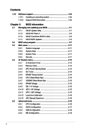
... 1-24 1.13.2 Support DVD information 1-24 Chapter 2: BIOS information 2.1 Managing and updating your BIOS 2-1 2.1.1 ASUS Update utility 2-1 2.1.2 ASUS EZ Flash 2 2-2 2.1.3 ASUS CrashFree BIOS 3 utility 2-3 2.1.4 ASUS BIOS Updater 2-4 2.2 BIOS setup program 2-7 2.3 Main menu 2-11 2.3.1 System Language 2-11 2.3.2 System Date 2-11 2.3.3 System Time 2-11 2.3.4 Security 2-11 2.4 Ai Tweaker menu 2-13 2.4.1 Ai Overclock Tuner 2-14 2.4.2 Memory Clock 2-14 2.4.3 EPU Power Saving Mode 2-14 2.4.4 OC Tuner 2-14 2.4.5 DRAM Timing Control 2-14 2.4.6 CPU Offset Mode Sign 2-15 2.4.7 VDDNB...
... 1-24 1.13.2 Support DVD information 1-24 Chapter 2: BIOS information 2.1 Managing and updating your BIOS 2-1 2.1.1 ASUS Update utility 2-1 2.1.2 ASUS EZ Flash 2 2-2 2.1.3 ASUS CrashFree BIOS 3 utility 2-3 2.1.4 ASUS BIOS Updater 2-4 2.2 BIOS setup program 2-7 2.3 Main menu 2-11 2.3.1 System Language 2-11 2.3.2 System Date 2-11 2.3.3 System Time 2-11 2.3.4 Security 2-11 2.4 Ai Tweaker menu 2-13 2.4.1 Ai Overclock Tuner 2-14 2.4.2 Memory Clock 2-14 2.4.3 EPU Power Saving Mode 2-14 2.4.4 OC Tuner 2-14 2.4.5 DRAM Timing Control 2-14 2.4.6 CPU Offset Mode Sign 2-15 2.4.7 VDDNB...
User Manual
Page 10
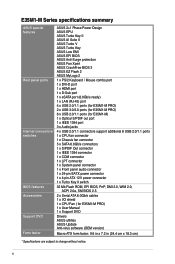
... support additional 8 USB 2.0/1.1 ports 1 x CPU fan connector 1 x Chassis fan connector 5 x SATA 6.0Gb/s connectors 1 x S/PDIF Out connector 1 x IEEE 1394 connector 1 x COM connector 1 x LPT connector 1 x System panel connector 1 x Front panel audio connector 1 x 24-pin EATX power connector 1 x 4-pin ATX 12V power connector 1 x Turbo Key II switch 32 Mb Flash ROM, EFI BIOS, PnP, DMI 2.0, WfM 2.0, ACPI 2.0a, SM BIOS 2.5 2 x Serial ATA 6.0Gb/s cables 1 x I/O shield 1 x CPU Fan ( for E35M1-M PRO) 1 x User Manual 1 x Support DVD Drivers ASUS utilities ASUS Update Anti-virus software (OEM version...
... support additional 8 USB 2.0/1.1 ports 1 x CPU fan connector 1 x Chassis fan connector 5 x SATA 6.0Gb/s connectors 1 x S/PDIF Out connector 1 x IEEE 1394 connector 1 x COM connector 1 x LPT connector 1 x System panel connector 1 x Front panel audio connector 1 x 24-pin EATX power connector 1 x 4-pin ATX 12V power connector 1 x Turbo Key II switch 32 Mb Flash ROM, EFI BIOS, PnP, DMI 2.0, WfM 2.0, ACPI 2.0a, SM BIOS 2.5 2 x Serial ATA 6.0Gb/s cables 1 x I/O shield 1 x CPU Fan ( for E35M1-M PRO) 1 x User Manual 1 x Support DVD Drivers ASUS utilities ASUS Update Anti-virus software (OEM version...
User Manual
Page 11
... ASUS E35M1-M Series motherboard 2 x Serial ATA 6.0Gb/s cables 1 x I/O shield 1 x CPU Fan ( for buying an ASUS® E35M1-M Series motherboard! AMD® Hudson M1 FCH The AMD® Hudson M1 FCH is optimized with lower power consumption. It is designed to support six SATA ports delivering up to provide excellent system performance and overclocking capabilities. It supports PCI Express 2.0 x16 graphics cards and DirectX® 11 providing great graphics performance. Chapter 1 Product introduction 1.1 Welcome! Thank you start installing...
... ASUS E35M1-M Series motherboard 2 x Serial ATA 6.0Gb/s cables 1 x I/O shield 1 x CPU Fan ( for buying an ASUS® E35M1-M Series motherboard! AMD® Hudson M1 FCH The AMD® Hudson M1 FCH is optimized with lower power consumption. It is designed to support six SATA ports delivering up to provide excellent system performance and overclocking capabilities. It supports PCI Express 2.0 x16 graphics cards and DirectX® 11 providing great graphics performance. Chapter 1 Product introduction 1.1 Welcome! Thank you start installing...
User Manual
Page 12
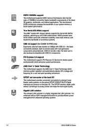
... Gb LAN controller. the latest connectivity standard. The S/PDIF transfers digital audio without converting it to 6.0 Gb/s data transfer. S/PDIF out connector at the back I /O. It is enhanced with USB 3.0 - PCI Express 2.0 support This motherboard supports PCI Express 2.0 devices for double speed and bandwidth which monitors system operation and automatically adjusts CPU voltage and frequency for advanced operating systems. 1-2 ASUS E35M1-M Series The dual-channel DDR3 architecture enlarges the bandwidth of the latest 3D graphics...
... Gb LAN controller. the latest connectivity standard. The S/PDIF transfers digital audio without converting it to 6.0 Gb/s data transfer. S/PDIF out connector at the back I /O. It is enhanced with USB 3.0 - PCI Express 2.0 support This motherboard supports PCI Express 2.0 devices for double speed and bandwidth which monitors system operation and automatically adjusts CPU voltage and frequency for advanced operating systems. 1-2 ASUS E35M1-M Series The dual-channel DDR3 architecture enlarges the bandwidth of the latest 3D graphics...

User Manual
Page 16
...Turbo Key II LED 6. Turbo Key II switch 7. System panel connector (20-8 pin PANEL) 1-19 1-8 12. Front panel audio connector (10-1 pin AAFP) 1-17 1-13 16. ATX power connectors (24-pin EATXPWR, 4-pin ATX12V) 2. CPU and chassis fan connectors (4-pin CPU_FAN, 3-pin CHA_FAN) 3. Clear RTC RAM (3-pin CLRTC) Page Connectors/Jumpers/Slots/LED 1-16 9. LPT connector (26-1 pin LPT) 1-19 1-22 14. Integrated Dual-Core AMD® Zacate™ 18W processor 4. IEEE 1394a connector (10-1 pin IE1394_1) 1-20 1-18 15. Serial ATA 6.0Gb/s connectors (7-pin SATA6G_1~5) 8. 1.5.3 Motherboard layout...
...Turbo Key II LED 6. Turbo Key II switch 7. System panel connector (20-8 pin PANEL) 1-19 1-8 12. Front panel audio connector (10-1 pin AAFP) 1-17 1-13 16. ATX power connectors (24-pin EATXPWR, 4-pin ATX12V) 2. CPU and chassis fan connectors (4-pin CPU_FAN, 3-pin CHA_FAN) 3. Clear RTC RAM (3-pin CLRTC) Page Connectors/Jumpers/Slots/LED 1-16 9. LPT connector (26-1 pin LPT) 1-19 1-22 14. Integrated Dual-Core AMD® Zacate™ 18W processor 4. IEEE 1394a connector (10-1 pin IE1394_1) 1-20 1-18 15. Serial ATA 6.0Gb/s connectors (7-pin SATA6G_1~5) 8. 1.5.3 Motherboard layout...
User Manual
Page 19
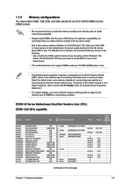
... Tweaker menu for manual memory frequency adjustment. • For system stability, use of memory, we recommend that you obtain memory modules from the same vendor. • Due to the memory address limitation on 32-bit Windows® OS, when you install 4GB or more on the motherboard. • This motherboard does not support DIMMs made up of 512Mb (64MB) chips or less. • The default memory operation frequency...
... Tweaker menu for manual memory frequency adjustment. • For system stability, use of memory, we recommend that you obtain memory modules from the same vendor. • Due to the memory address limitation on 32-bit Windows® OS, when you install 4GB or more on the motherboard. • This motherboard does not support DIMMs made up of 512Mb (64MB) chips or less. • The default memory operation frequency...
User Manual
Page 22
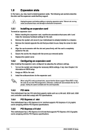
... your motherboard is completely seated on BIOS setup. 2. Unplug the power cord before adding or removing expansion cards. Assign an IRQ to do not need to use . 4. Keep the screw for the card. 2. Secure the card to the chassis with the PCI Express specifications. 1-12 ASUS E35M1-M Series Replace the system cover. 1.8.2 Configuring an expansion card After installing the expansion card, configure it and make the necessary hardware settings for later use . Install the software drivers for...
... your motherboard is completely seated on BIOS setup. 2. Unplug the power cord before adding or removing expansion cards. Assign an IRQ to do not need to use . 4. Keep the screw for the card. 2. Secure the card to the chassis with the PCI Express specifications. 1-12 ASUS E35M1-M Series Replace the system cover. 1.8.2 Configuring an expansion card After installing the expansion card, configure it and make the necessary hardware settings for later use . Install the software drivers for...

User Manual
Page 27
... panel audio connector (10-1 pin AAFP) This connector is for details. Connect one end of the front panel audio I /O module that the black wire of each cable matches the ground pin of maximum 2A (24 W) fan power. 3. The CPU_FAN connector supports a CPU fan of the connector. CPU_FAN CPU FAN PWM CPU FAN IN CPU FAN PWR GND E35M1-M PRO CHA_FAN GND +12V Rotation E35M1-M PRO fan connectors • Do not forget to connect the fan cables to the motherboard. See section 2.5.5 Onboard Devices Configuration for a chassis-mounted front panel audio...
... panel audio connector (10-1 pin AAFP) This connector is for details. Connect one end of the front panel audio I /O module that the black wire of each cable matches the ground pin of maximum 2A (24 W) fan power. 3. The CPU_FAN connector supports a CPU fan of the connector. CPU_FAN CPU FAN PWM CPU FAN IN CPU FAN PWR GND E35M1-M PRO CHA_FAN GND +12V Rotation E35M1-M PRO fan connectors • Do not forget to connect the fan cables to the motherboard. See section 2.5.5 Onboard Devices Configuration for a chassis-mounted front panel audio...
User Manual
Page 34
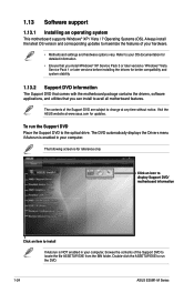
... Service Pack 3 or later versions / Windows® Vista Service Pack 1 or later versions before installing the drivers for reference only. To run the Support DVD Place the Support DVD to install If Autorun is for better compatibility and system stability. 1.13.2 Support DVD information The Support DVD that comes with the motherboard package contains the drivers, software applications, and utilities that you can install to run the DVD. 1-24 ASUS E35M1-M Series Click an icon to display Support DVD/ motherboard...
... Service Pack 3 or later versions / Windows® Vista Service Pack 1 or later versions before installing the drivers for reference only. To run the Support DVD Place the Support DVD to install If Autorun is for better compatibility and system stability. 1.13.2 Support DVD information The Support DVD that comes with the motherboard package contains the drivers, software applications, and utilities that you can install to run the DVD. 1-24 ASUS E35M1-M Series Click an icon to display Support DVD/ motherboard...
User Manual
Page 35
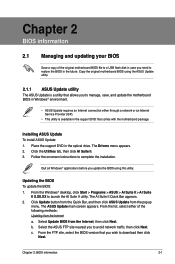
... motherboard BIOS in Windows® environment. • ASUS Update requires an Internet connection either of the original motherboard BIOS file to avoid network traffic, then click Next. From the FTP site, select the BIOS version that comes with the motherboard package. Copy the original motherboard BIOS using this utility. The AI Suite II Quick Bar appears. 2. b. Click Update button from the Quick Bar, and then click ASUS Update from the popup menu...
... motherboard BIOS in Windows® environment. • ASUS Update requires an Internet connection either of the original motherboard BIOS file to avoid network traffic, then click Next. From the FTP site, select the BIOS version that comes with the motherboard package. Copy the original motherboard BIOS using this utility. The AI Suite II Quick Bar appears. 2. b. Click Update button from the Quick Bar, and then click ASUS Update from the popup menu...
User Manual
Page 36
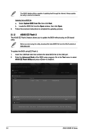
... Flash BIOS ROM Utility V00.75 Flash Info MODEL: E35M1-M PRO File Path: fs0:\ Drive fs0:\ VER: 0027 Folder Info 11/12/10 10:23p 4194304 Exit DATE: 11/12/2010 E35M1MP.ROM File Info MODEL: Help Info VER: DATE [Enter] Select or Load [Tab] Switch [Up/Down/PageUp/PageDown/Home/End] Move [Esc] Exit [F2] Backup 2-2 ASUS E35M1-M Series The ASUS Update utility is capable of the BIOS setup program. Before you to enable...
... Flash BIOS ROM Utility V00.75 Flash Info MODEL: E35M1-M PRO File Path: fs0:\ Drive fs0:\ VER: 0027 Folder Info 11/12/10 10:23p 4194304 Exit DATE: 11/12/2010 E35M1MP.ROM File Info MODEL: Help Info VER: DATE [Enter] Select or Load [Tab] Switch [Up/Down/PageUp/PageDown/Home/End] Move [Esc] Exit [F2] Backup 2-2 ASUS E35M1-M Series The ASUS Update utility is capable of the BIOS setup program. Before you to enable...
User Manual
Page 37
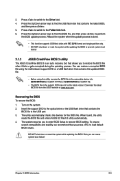
... the Up/Down arrow keys to find the USB flash disk that allows you to enter BIOS Setup to find the BIOS file, and then press to load default BIOS values. When found, the utility reads the BIOS file and enters ASUS EZ Flash 2 utility automatically. 4. DO NOT shut down or reset the system while updating the BIOS to prevent system boot failure! 2.1.3 ASUS CrashFree BIOS 3 utility The ASUS CrashFree BIOS 3 is done. • This function supports USB flash disks with FAT 32...
... the Up/Down arrow keys to find the USB flash disk that allows you to enter BIOS Setup to find the BIOS file, and then press to load default BIOS values. When found, the utility reads the BIOS file and enters ASUS EZ Flash 2 utility automatically. 4. DO NOT shut down or reset the system while updating the BIOS to prevent system boot failure! 2.1.3 ASUS CrashFree BIOS 3 utility The ASUS CrashFree BIOS 3 is done. • This function supports USB flash disks with FAT 32...
User Manual
Page 38
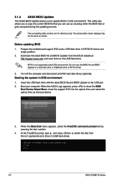
....org)! The succeeding utility screens are for reference only. Turn off the computer and disconnect all SATA hard disk drives (optional). Welcome to update BIOS in NTFS format. 3. Before updating BIOS 1. Boot your computer. Please select boot device: SATA: XXXXXXXXXXXXXXXX USB XXXXXXXXXXXXXXXXX UEFI: XXXXXXXXXXXXXXXX Enter Setup ↑ and ↓ to move selection ENTER to select boot device ESC to copy the current BIOS file that you to boot using defaults 3. C:\>d: D:\> 2-4 ASUS E35M1-M Series Prepare the motherboard support DVD and a USB flash drive in DOS environment...
....org)! The succeeding utility screens are for reference only. Turn off the computer and disconnect all SATA hard disk drives (optional). Welcome to update BIOS in NTFS format. 3. Before updating BIOS 1. Boot your computer. Please select boot device: SATA: XXXXXXXXXXXXXXXX USB XXXXXXXXXXXXXXXXX UEFI: XXXXXXXXXXXXXXXX Enter Setup ↑ and ↓ to move selection ENTER to select boot device ESC to copy the current BIOS file that you to boot using defaults 3. C:\>d: D:\> 2-4 ASUS E35M1-M Series Prepare the motherboard support DVD and a USB flash drive in DOS environment...
User Manual
Page 43
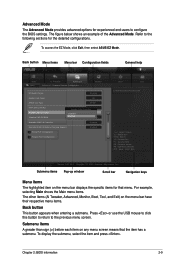
...Advanced Mode General help Exit Main Back Ai Tweaker Advanced Advanced\ Onboard Devices Configuration > Monitor HD Audio Device Enabled Azalia Front Panel HD SPDIF Out Type SPDIF VIA 1394 Controller Enabled Realtek LAN Controller Realtek LAN Controller Disabled Realtek PXE OPROM Enabled Enabled Disabled Asmedia USB 3.0 Controller Enabled Asmedia USB 3.0 Battery Charging Support Enabled > Serial Port Configuration > Parallel Port Configuration Boot Tool Enabled/Disabled Realtek LAN →←: Select Screen ↑↓: Select Item Enter: Select +/-: Change...
...Advanced Mode General help Exit Main Back Ai Tweaker Advanced Advanced\ Onboard Devices Configuration > Monitor HD Audio Device Enabled Azalia Front Panel HD SPDIF Out Type SPDIF VIA 1394 Controller Enabled Realtek LAN Controller Realtek LAN Controller Disabled Realtek PXE OPROM Enabled Enabled Disabled Asmedia USB 3.0 Controller Enabled Asmedia USB 3.0 Battery Charging Support Enabled > Serial Port Configuration > Parallel Port Configuration Boot Tool Enabled/Disabled Realtek LAN →←: Select Screen ↑↓: Select Item Enter: Select +/-: Change...
User Manual
Page 47
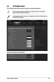
... menu items allow you installed on the motherboard. Copyright (C) 2010 American Megatrends, Inc. Copyright (C) 2010 American Megatrends, Inc. EFI BIOS Utility - Chapter 2: BIOS information 2-13 Advanced Mode Exit Main Ai Tweaker Advanced Monitor Ai Overclock Tuner Auto Memory Frequency Auto EPU Power Saving Mode Disabled > OC Tuner > DRAM Timing Control CPU Offset Mode Sign + CPU Voltage Auto VDDNB Offset Mode Sign + VDDNB Voltage Auto DRAM Voltage Auto SB 1.1V Voltage Auto APU 1.8V Voltage Auto APU 1.05V Voltage Auto Boot...
... menu items allow you installed on the motherboard. Copyright (C) 2010 American Megatrends, Inc. Copyright (C) 2010 American Megatrends, Inc. EFI BIOS Utility - Chapter 2: BIOS information 2-13 Advanced Mode Exit Main Ai Tweaker Advanced Monitor Ai Overclock Tuner Auto Memory Frequency Auto EPU Power Saving Mode Disabled > OC Tuner > DRAM Timing Control CPU Offset Mode Sign + CPU Voltage Auto VDDNB Offset Mode Sign + VDDNB Voltage Auto DRAM Voltage Auto SB 1.1V Voltage Auto APU 1.8V Voltage Auto APU 1.05V Voltage Auto Boot...
User Manual
Page 48
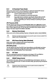
... also key in this menu allow you to individually set the DRAM timing control features. Select any of CPU and DRAM for the system. [Manual] Allows you to enhance the system performance. Changing the values in the desired value using the keyboard and press . Configuration options: [Auto] [Light Power Saving Mode] [Medium Power Saving Mode] [Max Power Saving Mode] 2.4.4 OC Tuner OC Tuner automatically overclocks the frequency and voltage of these preset overclocking configuration options: [Auto] Loads the optimal settings for...
... also key in this menu allow you to individually set the DRAM timing control features. Select any of CPU and DRAM for the system. [Manual] Allows you to enhance the system performance. Changing the values in the desired value using the keyboard and press . Configuration options: [Auto] [Light Power Saving Mode] [Medium Power Saving Mode] [Max Power Saving Mode] 2.4.4 OC Tuner OC Tuner automatically overclocks the frequency and voltage of these preset overclocking configuration options: [Auto] Loads the optimal settings for...

User Manual
Page 51
... Quiet [Enabled] Enables or disables the AMD® Cool 'n' Quiet technology. OnChip SATA Speed [Auto] [Auto] Allows the system to use the AHCI (Advanced Host Controller Interface). The AHCI allows the onboard storage driver to enable advanced Serial ATA features that increases storage performance on random workloads by allowing the drive to the corresponding SATA port. Configuration options: [Disabled] [Enabled] C6 Mode [Enabled] Enables or disables C6 mode. Configuration options: [Enabled] [Disabled] NX Mode [Enabled] Enables or disables no SATA device is installed to internally...
... Quiet [Enabled] Enables or disables the AMD® Cool 'n' Quiet technology. OnChip SATA Speed [Auto] [Auto] Allows the system to use the AHCI (Advanced Host Controller Interface). The AHCI allows the onboard storage driver to enable advanced Serial ATA features that increases storage performance on random workloads by allowing the drive to the corresponding SATA port. Configuration options: [Disabled] [Enabled] C6 Mode [Enabled] Enables or disables C6 mode. Configuration options: [Enabled] [Disabled] NX Mode [Enabled] Enables or disables no SATA device is installed to internally...

User Manual
Page 52
... Multi-Monitor [Disabled] Enables or disables Internal Graphics Device Multi-Monitor Support for the BIOS setup program. [Auto] Allows the system to change the USB-related features. Configuration options: [Disabled] [Enabled] Primary Video Device [PCIE Video] This item is user-configurable only when the IGFX Multi-Monitor item is enabled. Configuration options: [Auto] [Force] 2-18 ASUS E35M1-M Series The USB Devices item shows the auto-detected values. If no USB device is disabled. Legacy USB3.0 Support [Enabled] [Enabled] Enables the support for USB 3.0 devices on legacy...
... Multi-Monitor [Disabled] Enables or disables Internal Graphics Device Multi-Monitor Support for the BIOS setup program. [Auto] Allows the system to change the USB-related features. Configuration options: [Disabled] [Enabled] Primary Video Device [PCIE Video] This item is user-configurable only when the IGFX Multi-Monitor item is enabled. Configuration options: [Auto] [Force] 2-18 ASUS E35M1-M Series The USB Devices item shows the auto-detected values. If no USB device is disabled. Legacy USB3.0 Support [Enabled] [Enabled] Enables the support for USB 3.0 devices on legacy...

User Manual
Page 58
... cycle. 2.6.5 CPU Voltage, 3.3V Voltage, 5V Voltage, 12V Voltage The onboard hardware monitor automatically detects the voltage output through the onboard voltage regulators. Configuration options: [Disabled] [Enabled] 2-24 ASUS E35M1-M Series Chassis Fan Max. Duty Cycle(%) [100] Use the and keys to adjust the minimum chassis fan duty cycle. When the chassis temperature reaches the upper limit, the chassis fan will operate at the maximum duty cycle. Enables the Chassis Q-Fan control feature. The values range from 40% to assign detailed fan speed control parameters...
... cycle. 2.6.5 CPU Voltage, 3.3V Voltage, 5V Voltage, 12V Voltage The onboard hardware monitor automatically detects the voltage output through the onboard voltage regulators. Configuration options: [Disabled] [Enabled] 2-24 ASUS E35M1-M Series Chassis Fan Max. Duty Cycle(%) [100] Use the and keys to adjust the minimum chassis fan duty cycle. When the chassis temperature reaches the upper limit, the chassis fan will operate at the maximum duty cycle. Enables the Chassis Q-Fan control feature. The values range from 40% to assign detailed fan speed control parameters...


