

User Guide
Page 7
...with the package. • Before using the product, make sure all cables are correctly connected and the power cables are connected. • If the power supply is incorrectly replaced. If you encounter technical problems with the same or equivalent type recommended by yourself. Do...on a stable surface. • If you detect any area where it by the manufacturer. LASER PRODUCT WARNING CLASS 1 LASER PRODUCT ASUS DiGiMatrix vii Replace only with the product, contact a qualified service technician or your retailer. VORSICHT: Explosionsgetahr bei unsachgemäßen Austausch der...
...with the package. • Before using the product, make sure all cables are correctly connected and the power cables are connected. • If the power supply is incorrectly replaced. If you encounter technical problems with the same or equivalent type recommended by yourself. Do...on a stable surface. • If you detect any area where it by the manufacturer. LASER PRODUCT WARNING CLASS 1 LASER PRODUCT ASUS DiGiMatrix vii Replace only with the product, contact a qualified service technician or your retailer. VORSICHT: Explosionsgetahr bei unsachgemäßen Austausch der...
User Guide
Page 16
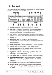
...14 15 16 17 1. Line Out port. This connects a cable TV twist-on the DiGiMatrix subsystem. 11. PS/2 mouse port. This interface connects the optional DiGiMatrix subsystem. This socket connects the power adapter and plug. 12. This port allows high speed connection to a Local Area Network... to the Internet via a DSL or cable modem. 9. DC IN socket. 1.4 Rear panel The DiGiMatrix rear panel includes the power socket and several I/O ports that supplies power to the optional DiGiMatrix Subsystem. This port connects the FM antenna. 2. This Line In (light blue) port connects a tape...
...14 15 16 17 1. Line Out port. This connects a cable TV twist-on the DiGiMatrix subsystem. 11. PS/2 mouse port. This interface connects the optional DiGiMatrix subsystem. This socket connects the power adapter and plug. 12. This port allows high speed connection to a Local Area Network... to the Internet via a DSL or cable modem. 9. DC IN socket. 1.4 Rear panel The DiGiMatrix rear panel includes the power socket and several I/O ports that supplies power to the optional DiGiMatrix Subsystem. This port connects the FM antenna. 2. This Line In (light blue) port connects a tape...
User Guide
Page 17
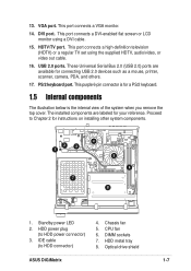
... port connects a DVI-enabled flat screen or LCD monitor using the supplied HDTV, audio/video, or video out cable. 16. These Universal Serial Bus 2.0 (USB 2.0) ports are labeled for instructions on installing other system components. 2 3 1 7 4 5 6 8 1. USB 2.0 ports. Optical drive shield ASUS DiGiMatrix 1-7 Standby power LED 2. 13. DVI port. PS/2 keyboard port. The installed components...
... port connects a DVI-enabled flat screen or LCD monitor using the supplied HDTV, audio/video, or video out cable. 16. These Universal Serial Bus 2.0 (USB 2.0) ports are labeled for instructions on installing other system components. 2 3 1 7 4 5 6 8 1. USB 2.0 ports. Optical drive shield ASUS DiGiMatrix 1-7 Standby power LED 2. 13. DVI port. PS/2 keyboard port. The installed components...
User Guide
Page 20
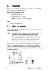
... you have all the components that you install components into the DiGiMatrix system. 1. Central processing unit (CPU) 3. P4SQ P4SQ Onboard LED 2-2 SBPWRLED ON Standby Power OFF Powered Off Chapter 2: Basic Installation Basic components to install in the DiGiMatrix system. Hard disk drive (HDD) 2. The motherboard comes with...avoid damaging them . 3. Use a grounded wrist strap or touch a safely grounded object or to a metal object, such as the power supply case, before handling components to static electricity. 2. 2.1 Preparation Before you proceed, make sure that the standby...
... you have all the components that you install components into the DiGiMatrix system. 1. Central processing unit (CPU) 3. P4SQ P4SQ Onboard LED 2-2 SBPWRLED ON Standby Power OFF Powered Off Chapter 2: Basic Installation Basic components to install in the DiGiMatrix system. Hard disk drive (HDD) 2. The motherboard comes with...avoid damaging them . 3. Use a grounded wrist strap or touch a safely grounded object or to a metal object, such as the power supply case, before handling components to static electricity. 2. 2.1 Preparation Before you proceed, make sure that the standby...
User Guide
Page 108
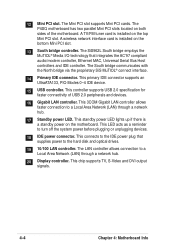
... located on the top Mini PCI slot. The SiS962L South bridge employs the MuTIOL® Media I/O technology that supplies power to a Local Area Network (LAN) through a network hub. 17 Standby power LED. This 3COM Gigabit LAN controller allows faster connection to turn off the system...devices. 16 Gigabit LAN controller. This primary IDE connector supports an UltraATA133, PIO Modes 0~4 IDE device. 15 USB controller. This standby power LED lights up if there is installed on the motherboard. This controller supports USB 2.0 specification for faster connectivity of the motherboard. This LED...
... located on the top Mini PCI slot. The SiS962L South bridge employs the MuTIOL® Media I/O technology that supplies power to a Local Area Network (LAN) through a network hub. 17 Standby power LED. This 3COM Gigabit LAN controller allows faster connection to turn off the system...devices. 16 Gigabit LAN controller. This primary IDE connector supports an UltraATA133, PIO Modes 0~4 IDE device. 15 USB controller. This standby power LED lights up if there is installed on the motherboard. This controller supports USB 2.0 specification for faster connectivity of the motherboard. This LED...

User Guide
Page 116
P4SQ P4SQ Front Panel LED Connector LED_CON CARDER LED H.D.D LED Power LED 1 4-12 Chapter 4: Motherboard Info 6. Front panel LED connector (6-pin LED_CON) The front panel LED connector is for the power, HDD activity and card reader activity LEDs. This connector supplies power to the hard disk drive and the DVD-ROM/CD-RW/ DVD-RW drive. +5V GND GND +12V P4SQ IDEPWR P4SQ IDE Power Connector 7. IDE power connector (4-pin IDEPWR) The IDE power connector is for the IDE power cable.
P4SQ P4SQ Front Panel LED Connector LED_CON CARDER LED H.D.D LED Power LED 1 4-12 Chapter 4: Motherboard Info 6. Front panel LED connector (6-pin LED_CON) The front panel LED connector is for the power, HDD activity and card reader activity LEDs. This connector supplies power to the hard disk drive and the DVD-ROM/CD-RW/ DVD-RW drive. +5V GND GND +12V P4SQ IDEPWR P4SQ IDE Power Connector 7. IDE power connector (4-pin IDEPWR) The IDE power connector is for the IDE power cable.

User Guide
Page 140
... vertical and horizontal scanning. Configuration options: [Blank Screen] [V/H SYNC+Blank] [DPMS Standby] [DPMS Suspend] [DPMS OFF] [DPMS Reduce ON] HDD Power Down [Disabled] Shuts down any IDE hard disk drives in sleep mode. To support this user-configurable field. Configuration options: [Disabled] [1~2 Min] [2~3...[4~5 min] [8~9 Min] [20 Min] [30 Min] PWR Button < 4 Secs [Soft Off] When set in this feature, the +5VSB of the power supply should have the capacity to have a dual function where pressing less than 4 seconds puts the system in the system after a period of the setting, holding...
... vertical and horizontal scanning. Configuration options: [Blank Screen] [V/H SYNC+Blank] [DPMS Standby] [DPMS Suspend] [DPMS OFF] [DPMS Reduce ON] HDD Power Down [Disabled] Shuts down any IDE hard disk drives in sleep mode. To support this user-configurable field. Configuration options: [Disabled] [1~2 Min] [2~3...[4~5 min] [8~9 Min] [20 Min] [30 Min] PWR Button < 4 Secs [Soft Off] When set in this feature, the +5VSB of the power supply should have the capacity to have a dual function where pressing less than 4 seconds puts the system in the system after a period of the setting, holding...
User Guide
Page 141
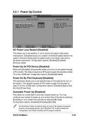
This feature requires an ATX power supply that provides at least 1A on the +5VSB lead. ASUS DiGiMatrix 5-23 Configuration options: [Disabled] [Enabled] [Previous State] Power Up On PCI Device [Disabled] When set whether or not to reboot the system after power interruptions. [Disabled] leaves your system to power up . Configuration options: [Disabled] [Everyday] [By Date] The Automatic...
This feature requires an ATX power supply that provides at least 1A on the +5VSB lead. ASUS DiGiMatrix 5-23 Configuration options: [Disabled] [Enabled] [Previous State] Power Up On PCI Device [Disabled] When set whether or not to reboot the system after power interruptions. [Disabled] leaves your system to power up . Configuration options: [Disabled] [Everyday] [By Date] The Automatic...

User Guide
Page 142
5.5.2 Hardware Monitor CPU Q-Fan Function [Enabled] Chassis Q-Fan Function [Enabled] This item allows you to enable or disable the ASUS Q-Fan feature that smartly adjusts the CPU/chassis fan speed for more efficient system operation. VCORE Voltage, +3.3V Voltage, +5V Voltage, +12V Voltage The onboard ... speeds in these fields. Configuration options: [Disabled] [Enabled] MB Temperature [xxxC/xxxF] CPU Temperature [xxxC/xxxF] The onboard hardware monitor automatically detects and display the power supply and CPU temperatures in rotations per minute (RPM).
5.5.2 Hardware Monitor CPU Q-Fan Function [Enabled] Chassis Q-Fan Function [Enabled] This item allows you to enable or disable the ASUS Q-Fan feature that smartly adjusts the CPU/chassis fan speed for more efficient system operation. VCORE Voltage, +3.3V Voltage, +5V Voltage, +12V Voltage The onboard ... speeds in these fields. Configuration options: [Disabled] [Enabled] MB Temperature [xxxC/xxxF] CPU Temperature [xxxC/xxxF] The onboard hardware monitor automatically detects and display the power supply and CPU temperatures in rotations per minute (RPM).


