CUV4X User Manual
Page 5
... SETUP 79 5.1 Operating Systems 79 5.1.1 Windows 98 First Time Installation 79 5.2 CUV4X Series Motherboard Support CD 80 5.3 Install ASUS PC Probe Vx.xx 81 5.4 Install PC-Cillin 98 Vx.xx 82 5.5 Install ADOBE AcroBat Reader Vx.xx 83 5.6 VIA... Fast Ethernet Card 97 7.2 Modem Riser 99 7.3 Glossary 101 ASUS CUV4X User's Manual 5 CONTENTS 4.4 Advanced Menu 56 4.4.1 Chip Configuration 60 4.4.2 I/O Device Configuration 63 4.4.3 PCI Configuration 66 4.4.4 Shadow Configuration 69 4.5 Power Menu 70 4.5.1 Power Up Control 72 4.5.2 Hardware Monitor 74 4.6 Boot Menu 75 ...
... SETUP 79 5.1 Operating Systems 79 5.1.1 Windows 98 First Time Installation 79 5.2 CUV4X Series Motherboard Support CD 80 5.3 Install ASUS PC Probe Vx.xx 81 5.4 Install PC-Cillin 98 Vx.xx 82 5.5 Install ADOBE AcroBat Reader Vx.xx 83 5.6 VIA... Fast Ethernet Card 97 7.2 Modem Riser 99 7.3 Glossary 101 ASUS CUV4X User's Manual 5 CONTENTS 4.4 Advanced Menu 56 4.4.1 Chip Configuration 60 4.4.2 I/O Device Configuration 63 4.4.3 PCI Configuration 66 4.4.4 Shadow Configuration 69 4.5 Power Menu 70 4.5.1 Power Up Control 72 4.5.2 Hardware Monitor 74 4.6 Boot Menu 75 ...
CUV4X User Manual
Page 9
Power supply is used .) • Super Multi-I/O: Provides two high-speed UART compatible serial ports and one parallel port with external peripherals, personal gadgets, or an optional remote controller. • Desktop Management Interface (DMI): Supports DMI through the onboard hardware ASUS ASIC and the bundled ASUS PC Probe. • SMBus: ...Flash EEPROM), offering enhanced ACPI for Windows 98 compatibility, built-in firmware-based virus protection, and autodetection of compatibility. (Requires DMI-enabled components.) ASUS CUV4X User's Manual 9 FEATURES Specifications 2.
Power supply is used .) • Super Multi-I/O: Provides two high-speed UART compatible serial ports and one parallel port with external peripherals, personal gadgets, or an optional remote controller. • Desktop Management Interface (DMI): Supports DMI through the onboard hardware ASUS ASIC and the bundled ASUS PC Probe. • SMBus: ...Flash EEPROM), offering enhanced ACPI for Windows 98 compatibility, built-in firmware-based virus protection, and autodetection of compatibility. (Requires DMI-enabled components.) ASUS CUV4X User's Manual 9 FEATURES Specifications 2.

CUV4X User Manual
Page 10
... burst transfer rate to 50% higher SDRAM speed at reduced power consumption of hard disk drives, PS/2 mouse, and Plug and Play devices to the memory and processor. • High-Speed Data Transfer Interface: IDE transfers using PC100-compliant SDRAMs). 10 ASUS CUV4X User's Manual The VCM's core design provides up to...
... burst transfer rate to 50% higher SDRAM speed at reduced power consumption of hard disk drives, PS/2 mouse, and Plug and Play devices to the memory and processor. • High-Speed Data Transfer Interface: IDE transfers using PC100-compliant SDRAMs). 10 ASUS CUV4X User's Manual The VCM's core design provides up to...
CUV4X User Manual
Page 11
... require much more protection. FEATURES 2.1.4 Intelligence • Auto Fan Off: The system fans will power off mode, depending on managing their computers from anywhere in sleep mode. ASUS CUV4X User's Manual 11 Suggestions will warn the user before the system resources are monitored to ensure... even in the world! • System Resources Alert: Today's operating systems such as information providers. When the power button is pressed for less than 4 seconds when the system is monitored by the ASUS ASIC through the CPU's internal thermal diode (on remotely through the...
... require much more protection. FEATURES 2.1.4 Intelligence • Auto Fan Off: The system fans will power off mode, depending on managing their computers from anywhere in sleep mode. ASUS CUV4X User's Manual 11 Suggestions will warn the user before the system resources are monitored to ensure... even in the world! • System Resources Alert: Today's operating systems such as information providers. When the power button is pressed for less than 4 seconds when the system is monitored by the ASUS ASIC through the CPU's internal thermal diode (on remotely through the...
CUV4X User Manual
Page 12
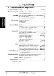
...) 21 Wake-On-LAN Connector 17 Wake-On-Ring Connector 13 Hardware Monitoring System Voltage Monitoring (integrated in ASUS ASIC) ....... 11 3 Fan Power and Speed Monitoring Connectors Power ATX Power Supply Connector 1 Special Feature Onboard LED 16 Form Factor ATX 12 ASUS CUV4X User's Manual FEATURES Motherboard Parts 2. Location Processor Support Socket 370 for locations. 2.
...) 21 Wake-On-LAN Connector 17 Wake-On-Ring Connector 13 Hardware Monitoring System Voltage Monitoring (integrated in ASUS ASIC) ....... 11 3 Fan Power and Speed Monitoring Connectors Power ATX Power Supply Connector 1 Special Feature Onboard LED 16 Form Factor ATX 12 ASUS CUV4X User's Manual FEATURES Motherboard Parts 2. Location Processor Support Socket 370 for locations. 2.

CUV4X User Manual
Page 14
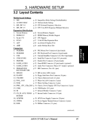
...(64/72-bit, 168-pin module) DIMM Socket 3 (64/72-bit, 168-pin module) PARALLEL PORT PWR_FAN Line Out Line In Mic In ATX Power Connector VIA VT82C694Z Chipset DIP Switches DIP_SW 0 1 2 3 4 5 Row GAME_AUDIO FLOPPY IDE Secondary Primary IDE Accelerated Graphics Port (AGP PRO) MIC2 PCI... Setting PCI 5 CHA_FAN SPDIFOUT Audio Modem Riser (AMR) WOR CUV4X ISA Slot VIA VT82C686A Chipset CR2032 3V Lithium Cell CMOS Power CLRTC JEN ASUS ASIC with Hardware Monitor JTPWR USBPORT SMB IDELED CHASSIS PANEL IR COM2 Flash EEPROM (Programable BIOS) Grayed components are optional at ...
...(64/72-bit, 168-pin module) DIMM Socket 3 (64/72-bit, 168-pin module) PARALLEL PORT PWR_FAN Line Out Line In Mic In ATX Power Connector VIA VT82C694Z Chipset DIP Switches DIP_SW 0 1 2 3 4 5 Row GAME_AUDIO FLOPPY IDE Secondary Primary IDE Accelerated Graphics Port (AGP PRO) MIC2 PCI... Setting PCI 5 CHA_FAN SPDIFOUT Audio Modem Riser (AMR) WOR CUV4X ISA Slot VIA VT82C686A Chipset CR2032 3V Lithium Cell CMOS Power CLRTC JEN ASUS ASIC with Hardware Monitor JTPWR USBPORT SMB IDELED CHASSIS PANEL IR COM2 Flash EEPROM (Programable BIOS) Grayed components are optional at ...
CUV4X User Manual
Page 15
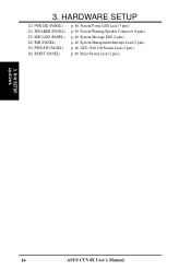
...12) WOL_CON p. 35 Wake-On-LAN Connector (3 pins) 13) WOR p. 35 Wake-On-Ring Connector (2 pins) 14) PWR_, CPU_,CHA_FAN p. 36 Chassis, Power Supply, CPU Fan Connectors (3 pins) 15) USB2 p. 36 USB Header (10-1 pins) 16) IR p. 37 Infrared Module Connector (5 pins) 17) CD_IN, AUX..., VIDEO p. 37 Internal Audio Connectors (4 4-pin) MODEM 18) ATXPWR p. 38 ATX Power Supply Connector (20 pins) 19) JTPWR p. 38 Power Supply Thermal Sensor Connector (2 pins) 20) SMB p. 39 SMBus Connector (5-1 pins) continued... H/W SETUP LayoutContents...
...12) WOL_CON p. 35 Wake-On-LAN Connector (3 pins) 13) WOR p. 35 Wake-On-Ring Connector (2 pins) 14) PWR_, CPU_,CHA_FAN p. 36 Chassis, Power Supply, CPU Fan Connectors (3 pins) 15) USB2 p. 36 USB Header (10-1 pins) 16) IR p. 37 Infrared Module Connector (5 pins) 17) CD_IN, AUX..., VIDEO p. 37 Internal Audio Connectors (4 4-pin) MODEM 18) ATXPWR p. 38 ATX Power Supply Connector (20 pins) 19) JTPWR p. 38 Power Supply Thermal Sensor Connector (2 pins) 20) SMB p. 39 SMBus Connector (5-1 pins) continued... H/W SETUP LayoutContents...
CUV4X User Manual
Page 16
3. HARDWARE SETUP 21) PWR.LED (PANEL) 22) SPEAKER (PANEL) 23) MSG.LED (PANEL) 24) SMI (PANEL) 25) PWR.SW (PANEL) 26) RESET (PANEL) p. 40 System Power LED Lead (3 pins) p. 40 System Warning Speaker Connector (4 pins) p. 40 System Message LED (2 pins) p. 40 System Management Interrupt Lead (2 pins) p. 40 ATX / Soft-Off Switch Lead (2 pins) p. 40 Reset Switch Lead (2 pins) 3. H/W SETUP LayoutContents 16 ASUS CUV4X User's Manual
3. HARDWARE SETUP 21) PWR.LED (PANEL) 22) SPEAKER (PANEL) 23) MSG.LED (PANEL) 24) SMI (PANEL) 25) PWR.SW (PANEL) 26) RESET (PANEL) p. 40 System Power LED Lead (3 pins) p. 40 System Warning Speaker Connector (4 pins) p. 40 System Message LED (2 pins) p. 40 System Management Interrupt Lead (2 pins) p. 40 ATX / Soft-Off Switch Lead (2 pins) p. 40 Reset Switch Lead (2 pins) 3. H/W SETUP LayoutContents 16 ASUS CUV4X User's Manual
CUV4X User Manual
Page 17
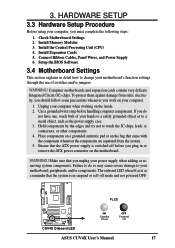
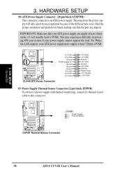
...do so may cause severe damage to touch the IC chips, leads or connectors, or other components. 4. WARNING! PLED CUV4X CUV4X Onboard LED ON Standby Power OFF Powered Off ASUS CUV4X User's Manual 17 To protect them against damage from the system. 5. Make sure that the ATX... power supply is in or remove the ATX power connector on your computer, you work on the motherboard. Failure to do not have one, touch both of switches and/or jumpers. Connect Ribbon ...
...do so may cause severe damage to touch the IC chips, leads or connectors, or other components. 4. WARNING! PLED CUV4X CUV4X Onboard LED ON Standby Power OFF Powered Off ASUS CUV4X User's Manual 17 To protect them against damage from the system. 5. Make sure that the ATX... power supply is in or remove the ATX power connector on your computer, you work on the motherboard. Failure to do not have one, touch both of switches and/or jumpers. Connect Ribbon ...

CUV4X User Manual
Page 22
... (Extended Data Output) chips. • BIOS shows SDRAM memory on the motherboard. Memory speed setup is the memory of choice for 3.3Volt (power level) unbuffered Synchronous Dynamic Random Access Memory (SDRAM) of the DIMM takes up one row on bootup screen. • Single-sided DIMMs come ...in 32, 64, 128, 256, 512MB. 22 ASUS CUV4X User's Manual This motherboard also supports NEC's Virtual Channel (VC) SDRAMs and Enhanced Memory System's High-speed DRAMs (HSDRAMs). stability. • SDRAM...
... (Extended Data Output) chips. • BIOS shows SDRAM memory on the motherboard. Memory speed setup is the memory of choice for 3.3Volt (power level) unbuffered Synchronous Dynamic Random Access Memory (SDRAM) of the DIMM takes up one row on bootup screen. • Single-sided DIMMs come ...in 32, 64, 128, 256, 512MB. 22 ASUS CUV4X User's Manual This motherboard also supports NEC's Virtual Channel (VC) SDRAMs and Enhanced Memory System's High-speed DRAMs (HSDRAMs). stability. • SDRAM...
CUV4X User Manual
Page 23
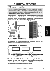
... notches on the DIMMs (see 3.3 Hardware Setup Procedure for more information). HARDWARE SETUP 3.5.2 Memory Installation WARNING! Insert the module(s) as shown. ASUS CUV4X User's Manual 23 3. Failure to do so may cause severe damage to prevent the wrong type from being inserted into the DIMM slot ...SIMM modules have a higher pin density. 88 Pins 60 Pins CUV4X 20 Pins CUV4X 168-Pin DIMM Sockets The DIMMs must tell your power supply when adding or removing memory modules or other system components. Make sure that you unplug your retailer the correct DIMM type before ...
... notches on the DIMMs (see 3.3 Hardware Setup Procedure for more information). HARDWARE SETUP 3.5.2 Memory Installation WARNING! Insert the module(s) as shown. ASUS CUV4X User's Manual 23 3. Failure to do so may cause severe damage to prevent the wrong type from being inserted into the DIMM slot ...SIMM modules have a higher pin density. 88 Pins 60 Pins CUV4X 20 Pins CUV4X 168-Pin DIMM Sockets The DIMMs must tell your power supply when adding or removing memory modules or other system components. Make sure that you unplug your retailer the correct DIMM type before ...

CUV4X User Manual
Page 26
... the necessary software drivers for possible future use . Secure the card on the slot you removed above. 5. H/W SETUP Expansion Cards 26 ASUS CUV4X User's Manual Unplug your motherboard and expansion cards. 3.7.1 Expansion Card Installation Procedure 1. Remove your computer system's cover and the bracket plate... on the slot with the screw you intend to both your power supply when adding or removing expansion cards or other system components. HARDWARE SETUP 3.7 Expansion Cards WARNING! Replace the computer system's cover. ...
... the necessary software drivers for possible future use . Secure the card on the slot you removed above. 5. H/W SETUP Expansion Cards 26 ASUS CUV4X User's Manual Unplug your motherboard and expansion cards. 3.7.1 Expansion Card Installation Procedure 1. Remove your computer system's cover and the bracket plate... on the slot with the screw you intend to both your power supply when adding or removing expansion cards or other system components. HARDWARE SETUP 3.7 Expansion Cards WARNING! Replace the computer system's cover. ...
CUV4X User Manual
Page 28
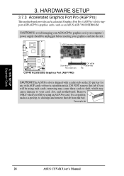
3. H/W SETUP Expansion Cards 28 ASUS CUV4X User's Manual To avoid damaging your AGP/AGP Pro graphics card, your computer's power supply should be using an AGP Pro card. removing may cause these cards to shift, which may cause damage to your graphics card into the ... unplugged before inserting your card, slot, and motherboard. Use a rigid tip, such as a pen tip, to support AGP/AGP Pro graphics cards, such as an ASUS AGP-V6800DDR/64M. The AGP Pro slot is shipped with a safety tab on the 20-pin bay for use with AGP cards without Retention Notch...
3. H/W SETUP Expansion Cards 28 ASUS CUV4X User's Manual To avoid damaging your AGP/AGP Pro graphics card, your computer's power supply should be using an AGP Pro card. removing may cause these cards to shift, which may cause damage to your graphics card into the ... unplugged before inserting your card, slot, and motherboard. Use a rigid tip, such as a pen tip, to support AGP/AGP Pro graphics cards, such as an ASUS AGP-V6800DDR/64M. The AGP Pro slot is shipped with a safety tab on the 20-pin bay for use with AGP cards without Retention Notch...

CUV4X User Manual
Page 30
... on standard AT keyboards. This connector will direct IRQ12 to the PS/2 mouse if one is for connectors or power sources. IDE ribbon cable must be exceptions. 3. PS/2 Keyboard (6-pin female) 30 ASUS CUV4X User's Manual Check the connectors before installation because there may be connected with the second drive connector no...
... on standard AT keyboards. This connector will direct IRQ12 to the PS/2 mouse if one is for connectors or power sources. IDE ribbon cable must be exceptions. 3. PS/2 Keyboard (6-pin female) 30 ASUS CUV4X User's Manual Check the connectors before installation because there may be connected with the second drive connector no...
CUV4X User Manual
Page 32
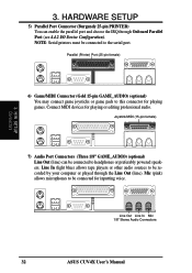
... game joysticks or game pads to the serial port. Mic (pink) allows microphones to headphones or preferably powered speakers. Parallel (Printer) Port (25-pin female) 3. Line Out Line In Mic 1/8" Stereo Audio Connectors 32 ASUS CUV4X User's Manual NOTE: Serial printers must be connected to be recorded by your computer or played...
... game joysticks or game pads to the serial port. Mic (pink) allows microphones to headphones or preferably powered speakers. Parallel (Printer) Port (25-pin female) 3. Line Out Line In Mic 1/8" Stereo Audio Connectors 32 ASUS CUV4X User's Manual NOTE: Serial printers must be connected to be recorded by your computer or played...
CUV4X User Manual
Page 33
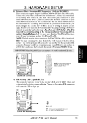
...and select the boot disk through 4.4.1 Advanced CMOS Setup. CUV4X PIN 1 CUV4X IDE Connectors 9) IDE Activity LED (2-pin IDELED) This connector supplies power to PIN 1. Connect the cable's blue connector to the motherboard's primary (recommended) or secondary IDE connector, and then connect the gray connector ... purchase another for the jumper settings. TIP: You may install one for the primary IDE connector and another UltraDMA/66 cable. ASUS CUV4X User's Manual 33 IMPORTANT: UltraDMA/66 IDE devices must configure the second drive to Slave mode by devices connected to the...
...and select the boot disk through 4.4.1 Advanced CMOS Setup. CUV4X PIN 1 CUV4X IDE Connectors 9) IDE Activity LED (2-pin IDELED) This connector supplies power to PIN 1. Connect the cable's blue connector to the motherboard's primary (recommended) or secondary IDE connector, and then connect the gray connector ... purchase another for the jumper settings. TIP: You may install one for the primary IDE connector and another UltraDMA/66 cable. ASUS CUV4X User's Manual 33 IMPORTANT: UltraDMA/66 IDE devices must configure the second drive to Slave mode by devices connected to the...
CUV4X User Manual
Page 35
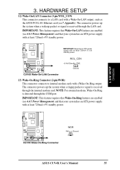
... enabled (see 7. H/W SETUP Connectors CUV4X CUV4X Wake-On-Ring Connector WOR RI# Ground 2 1 ASUS CUV4X User's Manual 35 IMPORTANT: Requires an ATX power supply with at least 720mA +5V standby power. 3. WOL_CON +5 Volt Standby PME CUV4X CUV4X Wake-On-LAN Connector Ground 13) Wake-On-Ring ...system has an ATX power supply with at least 720mA +5 volt standby power. HARDWARE SETUP 12) Wake-On-LAN Connector (3-pin WOL_CON) This connector connects to internal modem cards with a Wake-On-LAN output, such as the ASUS PCI-L101 Ethernet card (see 4.4.3 Power Management) and that ...
... enabled (see 7. H/W SETUP Connectors CUV4X CUV4X Wake-On-Ring Connector WOR RI# Ground 2 1 ASUS CUV4X User's Manual 35 IMPORTANT: Requires an ATX power supply with at least 720mA +5V standby power. 3. WOL_CON +5 Volt Standby PME CUV4X CUV4X Wake-On-LAN Connector Ground 13) Wake-On-Ring ...system has an ATX power supply with at least 720mA +5 volt standby power. HARDWARE SETUP 12) Wake-On-LAN Connector (3-pin WOL_CON) This connector connects to internal modem cards with a Wake-On-LAN output, such as the ASUS PCI-L101 Ethernet card (see 4.4.3 Power Management) and that ...
CUV4X User Manual
Page 36
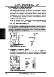
... 2-port USB connector set and mount the bracket to the board taking into consideration the polarity of the connector. HARDWARE SETUP 14) Power Supply, CPU, Chassis Fan Connectors (3-pin PWR_FAN, CPU_FAN1, CHA_FAN) These connectors support cooling fans of the expansion slots. NOTE: The... connectors on your chassis. USBP2+ GND NC 1 5 6 10 USB Power USBP3- SOFTWARE REFERENCE). 3. USBPORT Rotation +12V GND Rotation +12V GND USB Power USBP2- USBP3+ GND CUV4X CUV4X Front Panel USB Header 36 ASUS CUV4X User's Manual WARNING! Orientate the fans so that the heat sink ...
... 2-port USB connector set and mount the bracket to the board taking into consideration the polarity of the connector. HARDWARE SETUP 14) Power Supply, CPU, Chassis Fan Connectors (3-pin PWR_FAN, CPU_FAN1, CHA_FAN) These connectors support cooling fans of the expansion slots. NOTE: The... connectors on your chassis. USBP2+ GND NC 1 5 6 10 USB Power USBP3- SOFTWARE REFERENCE). 3. USBPORT Rotation +12V GND Rotation +12V GND USB Power USBP2- USBP3+ GND CUV4X CUV4X Front Panel USB Header 36 ASUS CUV4X User's Manual WARNING! Orientate the fans so that the heat sink ...

CUV4X User Manual
Page 37
... tuner, or MPEG card. The MODEM connector allows the onboard audio to the CIR and SIR connectors simultaneously for use Consumer Infrared (CIR) power up. Use the five pins as shown in order to the pin definitions. Front View Back View IR 1 CUV4X CUV4X Infrared Module Connector...as a speaker) between the onboard audio and a voice modem card. +5V (NC) IRRX GND IRTX 3. This module mounts to Modem) MODEM ASUS CUV4X User's Manual 37 HARDWARE SETUP 16) Standard and Consumer Infrared Module Connector (5-pin IR) This connector supports an optional wireless transmitting and receiving ...
... tuner, or MPEG card. The MODEM connector allows the onboard audio to the CIR and SIR connectors simultaneously for use Consumer Infrared (CIR) power up. Use the five pins as shown in order to the pin definitions. Front View Back View IR 1 CUV4X CUV4X Infrared Module Connector...as a speaker) between the onboard audio and a voice modem card. +5V (NC) IRRX GND IRTX 3. This module mounts to Modem) MODEM ASUS CUV4X User's Manual 37 HARDWARE SETUP 16) Standard and Consumer Infrared Module Connector (5-pin IR) This connector supports an optional wireless transmitting and receiving ...
CUV4X User Manual
Page 38
... Connector (20-pin block ATXPWR) This connector connects to this connector. You may experience difficulty in one orientation because of the different hole sizes. 3. JTPWR Power Supply Thermal Sensor CUV4X CUV4X Thermal Sensor Connector 38 ASUS CUV4X User's Manual Find the proper orientation and push down firmly making sure that your ATX...
... Connector (20-pin block ATXPWR) This connector connects to this connector. You may experience difficulty in one orientation because of the different hole sizes. 3. JTPWR Power Supply Thermal Sensor CUV4X CUV4X Thermal Sensor Connector 38 ASUS CUV4X User's Manual Find the proper orientation and push down firmly making sure that your ATX...


