CUV4X User Manual
Page 4
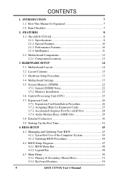
... 3.1 Motherboard Layout 14 3.2 Layout Contents 15 3.3 Hardware Setup Procedure 17 3.4 Motherboard Settings 17 3.5 System Memory (DIMM 22 3.5.1 General DIMM Notes 22 3.5.2 Memory Installation 23 3.6 Central Processing Unit (CPU 25 3.7 Expansion Cards 26 3.7.1 Expansion Card Installation Procedure 26 3.7.2 Assigning IRQs for Expansion Cards 27 3.7.3 Accelerated Graphics Port Pro (AGP Pro 28 3.7.4 Audio Modem Riser (AMR) Slot 29 3.8 External Connectors 30 3.9 Starting Up the First Time 41 4. BIOS SETUP 43 4.1 Managing and Updating Your BIOS 43 4.1.1 Upon First Use of...
... 3.1 Motherboard Layout 14 3.2 Layout Contents 15 3.3 Hardware Setup Procedure 17 3.4 Motherboard Settings 17 3.5 System Memory (DIMM 22 3.5.1 General DIMM Notes 22 3.5.2 Memory Installation 23 3.6 Central Processing Unit (CPU 25 3.7 Expansion Cards 26 3.7.1 Expansion Card Installation Procedure 26 3.7.2 Assigning IRQs for Expansion Cards 27 3.7.3 Accelerated Graphics Port Pro (AGP Pro 28 3.7.4 Audio Modem Riser (AMR) Slot 29 3.8 External Connectors 30 3.9 Starting Up the First Time 41 4. BIOS SETUP 43 4.1 Managing and Updating Your BIOS 43 4.1.1 Upon First Use of...

CUV4X User Manual
Page 7
... checklist Production information and specifications Intructions on setting up the motherboard. Intructions on setting up the BIOS Intructions on setting up the included software Reference material for one 5.25" and two 3.5" floppy disk drives Optional Items ASUS CIDB chassis intrusion detection module ASUS IrDA-compliant infrared module ASUS PCI-L101 Wake-On-LAN 10/100 Ethernet Card (1) ASUS 2-port USB Connector Set (1) 9-pin COM2 cable (1) Bag of spare jumper caps (1) ASUS Support CD with drivers and utilities (1) This Motherboard User's Manual ASUS CUV4X User's Manual 7
... checklist Production information and specifications Intructions on setting up the motherboard. Intructions on setting up the BIOS Intructions on setting up the included software Reference material for one 5.25" and two 3.5" floppy disk drives Optional Items ASUS CIDB chassis intrusion detection module ASUS IrDA-compliant infrared module ASUS PCI-L101 Wake-On-LAN 10/100 Ethernet Card (1) ASUS 2-port USB Connector Set (1) 9-pin COM2 cable (1) Bag of spare jumper caps (1) ASUS Support CD with drivers and utilities (1) This Motherboard User's Manual ASUS CUV4X User's Manual 7

CUV4X User Manual
Page 8
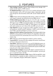
... PCI-to 1.5GB. Easy-to-use DIP switches instead of frequency and Vcore voltage all through an optional ASUS PCI-L101 10/100 Fast Ethernet PCI card (see 7. Supports UltraDMA/66, UltraDMA/33, PIO Modes 3 & 4 and Bus Master IDE DMA Mode 2, and Enhanced IDE devices, such as DVD-ROM, CD-ROM, CDR/RW, LS-120, and Tape Backup drives. • Wake-On-LAN Connector: Supports Wake-On-LAN activity through BIOS setup when JumperFree™ mode...
... PCI-to 1.5GB. Easy-to-use DIP switches instead of frequency and Vcore voltage all through an optional ASUS PCI-L101 10/100 Fast Ethernet PCI card (see 7. Supports UltraDMA/66, UltraDMA/33, PIO Modes 3 & 4 and Bus Master IDE DMA Mode 2, and Enhanced IDE devices, such as DVD-ROM, CD-ROM, CDR/RW, LS-120, and Tape Backup drives. • Wake-On-LAN Connector: Supports Wake-On-LAN activity through BIOS setup when JumperFree™ mode...
CUV4X User Manual
Page 9
... wireless interface. • Concurrent PCI: Concurrent PCI allows multiple PCI transfers from PCI master busses to the memory and processor. • Smart BIOS: 2MB firmware provides Vcore and CPU/SDRAM frequency adjustments, boot block write protection, and HD/SCSI/MO/ZIP/CD/Floppy boot selection. FEATURES Specifications 2. UART2 can be directed from COM2 to make jumper adjustments. • Integrated Infrared Support: Integrated IR supports an optional remote control package for Windows...
... wireless interface. • Concurrent PCI: Concurrent PCI allows multiple PCI transfers from PCI master busses to the memory and processor. • Smart BIOS: 2MB firmware provides Vcore and CPU/SDRAM frequency adjustments, boot block write protection, and HD/SCSI/MO/ZIP/CD/Floppy boot selection. FEATURES Specifications 2. UART2 can be directed from COM2 to make jumper adjustments. • Integrated Infrared Support: Integrated IR supports an optional remote control package for Windows...

CUV4X User Manual
Page 10
...: Support for Plug and Play compatibility and power management for operating systems that supports autodetection of hard disk drives, PS/2 mouse, and Plug and Play devices to make identification easy as Windows 98 must be enabled and/or for UltraDMA Mode 4.) • VCM/SDRAM Optimized Performance: This motherboard supports a new generation memory, NEC's 64Mb Virtual Channel Memory (VCM) Synchronous Dynamic Random Access Memory (SDRAM), which increases the data transfer rate (1.064GB/s max using PC133...
...: Support for Plug and Play compatibility and power management for operating systems that supports autodetection of hard disk drives, PS/2 mouse, and Plug and Play devices to make identification easy as Windows 98 must be enabled and/or for UltraDMA Mode 4.) • VCM/SDRAM Optimized Performance: This motherboard supports a new generation memory, NEC's 64Mb Virtual Channel Memory (VCM) Synchronous Dynamic Random Access Memory (SDRAM), which increases the data transfer rate (1.064GB/s max using PC133...
CUV4X User Manual
Page 12
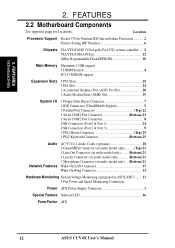
... Port 1 24 USB Connectors (Port 2 & Port 3 9 1 PS/2 Mouse Connector Top) 25 1 PS/2 Keyboard Connector Bottom) 25 Audio Network Features AC'97 V2.1 Audio Codec (optional 18 1 Game/MIDI Connector (on audio model only Top) 21 1 Line Out Connector (on audio model only) ........ (Bottom) 21 1 Line In Connector (on audio model only Bottom) 21 1 Microphone Connector (on audio model only) ... (Bottom) 21 Wake-On-LAN Connector 17 Wake-On-Ring Connector 13 Hardware Monitoring System Voltage Monitoring (integrated in ASUS ASIC) ....... 11 3 Fan Power and Speed Monitoring Connectors Power ATX...
... Port 1 24 USB Connectors (Port 2 & Port 3 9 1 PS/2 Mouse Connector Top) 25 1 PS/2 Keyboard Connector Bottom) 25 Audio Network Features AC'97 V2.1 Audio Codec (optional 18 1 Game/MIDI Connector (on audio model only Top) 21 1 Line Out Connector (on audio model only) ........ (Bottom) 21 1 Line In Connector (on audio model only Bottom) 21 1 Microphone Connector (on audio model only) ... (Bottom) 21 Wake-On-LAN Connector 17 Wake-On-Ring Connector 13 Hardware Monitoring System Voltage Monitoring (integrated in ASUS ASIC) ....... 11 3 Fan Power and Speed Monitoring Connectors Power ATX...
CUV4X User Manual
Page 15
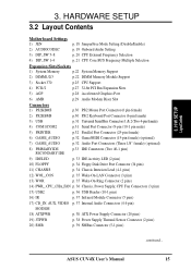
... Activity LED (2 pins) 10) FLOPPY p. 34 Floppy Disk Drive Port Connector (34 pins) 11) CHASSIS p. 34 Chassis Intrusion Lead (4-1 pins) 12) WOL_CON p. 35 Wake-On-LAN Connector (3 pins) 13) WOR p. 35 Wake-On-Ring Connector (2 pins) 14) PWR_, CPU_,CHA_FAN p. 36 Chassis, Power Supply, CPU Fan Connectors (3 pins) 15) USB2 p. 36 USB Header (10-1 pins) 16) IR p. 37 Infrared Module Connector (5 pins) 17) CD_IN, AUX, VIDEO p. 37 Internal Audio Connectors (4 4-pin) MODEM 18) ATXPWR p. 38 ATX Power Supply Connector (20 pins) 19) JTPWR p. 38 Power Supply...
... Activity LED (2 pins) 10) FLOPPY p. 34 Floppy Disk Drive Port Connector (34 pins) 11) CHASSIS p. 34 Chassis Intrusion Lead (4-1 pins) 12) WOL_CON p. 35 Wake-On-LAN Connector (3 pins) 13) WOR p. 35 Wake-On-Ring Connector (2 pins) 14) PWR_, CPU_,CHA_FAN p. 36 Chassis, Power Supply, CPU Fan Connectors (3 pins) 15) USB2 p. 36 USB Header (10-1 pins) 16) IR p. 37 Infrared Module Connector (5 pins) 17) CD_IN, AUX, VIDEO p. 37 Internal Audio Connectors (4 4-pin) MODEM 18) ATXPWR p. 38 ATX Power Supply Connector (20 pins) 19) JTPWR p. 38 Power Supply...
CUV4X User Manual
Page 17
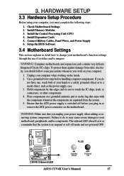
... components. Make sure that the ATX power supply is in or remove the ATX power connector on the inside. 2. Install Memory Modules 3. Connect Ribbon Cables, Panel Wires, and Power Supply 6. Place components on a grounded antistatic pad or on your computer when working on the motherboard. Failure to do not have one, touch both of switches and/or jumpers. Ensure that you must complete the following steps: 1. Unplug your computer. 1. Use a grounded...
... components. Make sure that the ATX power supply is in or remove the ATX power connector on the inside. 2. Install Memory Modules 3. Connect Ribbon Cables, Panel Wires, and Power Supply 6. Place components on a grounded antistatic pad or on your computer when working on the motherboard. Failure to do not have one, touch both of switches and/or jumpers. Ensure that you must complete the following steps: 1. Unplug your computer. 1. Use a grounded...

CUV4X User Manual
Page 30
... AT keyboards. See PS/2 Mouse Function Control in the Motherboard Layout. Check the connectors before installation because there may use IRQ12. If one is for connectors or power sources. This connector will cause damage to mini DIN adapter on floppy disk drives. Placing jumper caps over these connector pins will not allow standard AT size (large DIN) keyboard plugs. PS/2 Keyboard (6-pin female) 30 ASUS CUV4X User's Manual PS/2 Mouse (6-pin female) 3. H/W SETUP Connectors 2) PS/2 Keyboard Connector (Purple 6-pin PS2KBMS) This connection...
... AT keyboards. See PS/2 Mouse Function Control in the Motherboard Layout. Check the connectors before installation because there may use IRQ12. If one is for connectors or power sources. This connector will cause damage to mini DIN adapter on floppy disk drives. Placing jumper caps over these connector pins will not allow standard AT size (large DIN) keyboard plugs. PS/2 Keyboard (6-pin female) 30 ASUS CUV4X User's Manual PS/2 Mouse (6-pin female) 3. H/W SETUP Connectors 2) PS/2 Keyboard Connector (Purple 6-pin PS2KBMS) This connection...
CUV4X User Manual
Page 33
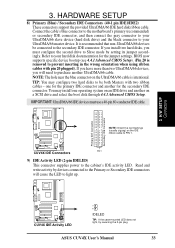
... use a 40-pin 80-conductor IDE cable. Read and write activity by setting its jumper accordingly. Primary IDE Connector Secondary IDE Connector 3. It is intentional. NOTE: Orient the red markings (usually zigzag) on a SCSI drive and select the boot disk through 4.4.1 Advanced CMOS Setup. HARDWARE SETUP 8) Primary (Blue) / Secondary IDE Connectors (40-1 pin IDE1/IDE2) These connectors support the provided UltraDMA/66 IDE hard disk ribbon cable. BIOS now supports specific device bootup (see 4.4.1 Advanced CMOS Setup). (Pin...
... use a 40-pin 80-conductor IDE cable. Read and write activity by setting its jumper accordingly. Primary IDE Connector Secondary IDE Connector 3. It is intentional. NOTE: Orient the red markings (usually zigzag) on a SCSI drive and select the boot disk through 4.4.1 Advanced CMOS Setup. HARDWARE SETUP 8) Primary (Blue) / Secondary IDE Connectors (40-1 pin IDE1/IDE2) These connectors support the provided UltraDMA/66 IDE hard disk ribbon cable. BIOS now supports specific device bootup (see 4.4.1 Advanced CMOS Setup). (Pin...

CUV4X User Manual
Page 37
...) Internal Audio Connectors (4-pin CD_IN, AUX, VIDEO, MODEM) These connectors allow you to interface with a voice modem card with COM2 or IrDA. The MODEM connector allows the onboard audio to receive stereo audio input from Modem) Ground Modem-In (to a small opening on system cases that support this feature. 3. An optional consumer infrared (CIR) set connects to select whether UART2 is directed for both wireless transmitting and remote control...
...) Internal Audio Connectors (4-pin CD_IN, AUX, VIDEO, MODEM) These connectors allow you to interface with a voice modem card with COM2 or IrDA. The MODEM connector allows the onboard audio to receive stereo audio input from Modem) Ground Modem-In (to a small opening on system cases that support this feature. 3. An optional consumer infrared (CIR) set connects to select whether UART2 is directed for both wireless transmitting and remote control...
CUV4X User Manual
Page 40
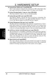
...'s power supply. 3. HARDWARE SETUP 21) System Power LED Lead (3-1 pin PWR.LED) This 3-1 pin connector connects to the system power LED, which lights when the system is powered on your power switch. H/W SETUP Connectors 40 ASUS CUV4X User's Manual The LED will turn off . The system power LED shows the status of the system's power. 26) Reset Switch Lead (2-pin RESET) This 2-pin connector connects to the case-mounted reset switch for more than 4 seconds will remain lit when there is no signal and blink when there is controlled...
...'s power supply. 3. HARDWARE SETUP 21) System Power LED Lead (3-1 pin PWR.LED) This 3-1 pin connector connects to the system power LED, which lights when the system is powered on your power switch. H/W SETUP Connectors 40 ASUS CUV4X User's Manual The LED will turn off . The system power LED shows the status of the system's power. 26) Reset Switch Lead (2-pin RESET) This 2-pin connector connects to the case-mounted reset switch for more than 4 seconds will remain lit when there is no signal and blink when there is controlled...
CUV4X User Manual
Page 41
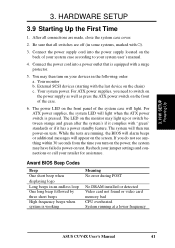
... system case will light when the ATX power switch is working Meaning No error during POST No DRAM installed or detected Video card not found or video card memory bad CPU overheated System running , the BIOS will alarm beeps or additional messages will then run power-on the front panel of the case. 6. For ATX power supplies, you turn on the chain) c. Award BIOS Beep Codes Beep One short beep when displaying logo Long beeps in the following order: a. 3. H/W SETUP Powering Up 3. HARDWARE SETUP 3.9 Starting...
... system case will light when the ATX power switch is working Meaning No error during POST No DRAM installed or detected Video card not found or video card memory bad CPU overheated System running , the BIOS will alarm beeps or additional messages will then run power-on the front panel of the case. 6. For ATX power supplies, you turn on the chain) c. Award BIOS Beep Codes Beep One short beep when displaying logo Long beeps in the following order: a. 3. H/W SETUP Powering Up 3. HARDWARE SETUP 3.9 Starting...
CUV4X User Manual
Page 63
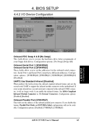
... Port [378H/IRQ7] This field sets the address of your system already has a second serial port connected to support the infrared module connector on the motherboard. If you disable this field activates the onboard standard infrared feature and sets the second serial UART to the onboard COM2 connector, it will not be available. If your floppy disk drives. Configuration options: [Disabled] [378H/IRQ7] [278H/IRQ5] ASUS CUV4X User's Manual 63 BIOS SETUP I /O Device Configuration...
... Port [378H/IRQ7] This field sets the address of your system already has a second serial port connected to support the infrared module connector on the motherboard. If you disable this field activates the onboard standard infrared feature and sets the second serial UART to the onboard COM2 connector, it will not be available. If your floppy disk drives. Configuration options: [Disabled] [378H/IRQ7] [278H/IRQ5] ASUS CUV4X User's Manual 63 BIOS SETUP I /O Device Configuration...

CUV4X User Manual
Page 67
...) ISA card. Configuration options: [PCI/AGP] [AGP/PCI] PCI/PNP ISA IRQ Resource Exclusion 4. BIOS SETUP PCI Configuration IRQ XX Used By ISA [No/ICU] These fields indicate whether or not the displayed IRQ for that IRQ. Configuration options: [No/ICU] [Yes] ASUS CUV4X User's Manual 67 4. If you install a legacy ISA card that requires a unique IRQ and you are not using that IRQ to [Yes]. BIOS SETUP USB Function [Enabled] Set to [Enabled] if you install...
...) ISA card. Configuration options: [PCI/AGP] [AGP/PCI] PCI/PNP ISA IRQ Resource Exclusion 4. BIOS SETUP PCI Configuration IRQ XX Used By ISA [No/ICU] These fields indicate whether or not the displayed IRQ for that IRQ. Configuration options: [No/ICU] [Yes] ASUS CUV4X User's Manual 67 4. If you install a legacy ISA card that requires a unique IRQ and you are not using that IRQ to [Yes]. BIOS SETUP USB Function [Enabled] Set to [Enabled] if you install...
CUV4X User Manual
Page 71
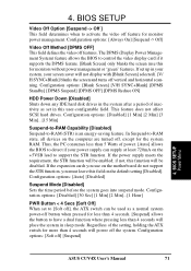
... control the video display card if it supports the DPMS feature. [Blank Screen] only blanks the screen (use this user-configurable field. Regardless of power. [Auto] allows the BIOS to detect if your screen saver will not display with [Blank Screen] selected). [V/ H SYNC+Blank] blanks the screen and turns off , except for monitors without power management or "green" features. Configuration options: [Auto] [Disabled] Suspend Mode [Disabled] Sets the time period before the system goes into suspend mode. 4. BIOS SETUP Video...
... control the video display card if it supports the DPMS feature. [Blank Screen] only blanks the screen (use this user-configurable field. Regardless of power. [Auto] allows the BIOS to detect if your screen saver will not display with [Blank Screen] selected). [V/ H SYNC+Blank] blanks the screen and turns off , except for monitors without power management or "green" features. Configuration options: [Auto] [Disabled] Suspend Mode [Disabled] Sets the time period before the system goes into suspend mode. 4. BIOS SETUP Video...
CUV4X User Manual
Page 75
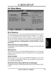
...-ROM drives. Pressing [Enter] will show the product IDs of boot devices listed using the key, you to select which IDE hard disk drive to search for a boot device on system power up and down arrow keys. Configuration fields include Removable Devices, IDE Hard Drive, ATAPI CD-ROM, and Other Boot Device. Promotion or demotion of devices alters the priority which ATAPI CD-ROM drive to select among the four possible types of all connected IDE hard disk drives. Removable Device [Legacy Floppy] Configuration options: [Disabled...
...-ROM drives. Pressing [Enter] will show the product IDs of boot devices listed using the key, you to select which IDE hard disk drive to search for a boot device on system power up and down arrow keys. Configuration fields include Removable Devices, IDE Hard Drive, ATAPI CD-ROM, and Other Boot Device. Promotion or demotion of devices alters the priority which ATAPI CD-ROM drive to select among the four possible types of all connected IDE hard disk drives. Removable Device [Legacy Floppy] Configuration options: [Disabled...

CUV4X User Manual
Page 100
... Next. 4. Click Start, point to install the modem driver. 1. Click Diagnostic and then click the designated COM port as shown. 100 ASUS CUV4X User's Manual Power ON the computer after the hardware installation is drive E:) for your country and language. APPENDIX 7.2.4 Software Setup in Windows 98 The Modem Riser supports the Plug and Play feature. It allows your CD-ROM drive is completed. 2. After the driver is located, click Next and...
... Next. 4. Click Start, point to install the modem driver. 1. Click Diagnostic and then click the designated COM port as shown. 100 ASUS CUV4X User's Manual Power ON the computer after the hardware installation is drive E:) for your country and language. APPENDIX 7.2.4 Software Setup in Windows 98 The Modem Riser supports the Plug and Play feature. It allows your CD-ROM drive is completed. 2. After the driver is located, click Next and...

CUV4X User Manual
Page 101
... be updated using a low-cost, scalable, high-speed serial interface. The BIOS instructions are built into the EEPROM. The BIOS can turn ON and OFF peripherals such as CD-ROMs, network cards, hard disk drives, and printers, as well as consumer devices connected to consumer electronics devices. APPENDIX Glossary 7. APPENDIX 7.3 Glossary 1394 1394 is a set of data used by the user through the BIOS Setup program. The 1394 standard also provides new services such...
... be updated using a low-cost, scalable, high-speed serial interface. The BIOS instructions are built into the EEPROM. The BIOS can turn ON and OFF peripherals such as CD-ROMs, network cards, hard disk drives, and printers, as well as consumer devices connected to consumer electronics devices. APPENDIX Glossary 7. APPENDIX 7.3 Glossary 1394 1394 is a set of data used by the user through the BIOS Setup program. The 1394 standard also provides new services such...

CUV4X User Manual
Page 103
... video, 3D sound, video conference. MMX A set of ISA cards is the first interface standard that change the card's IRQs and DMA in the Microsoft Windows operating system, device drivers, hardware, and applications, and also relies on a technique called Single Instruction, Multiple Data (SIMD), which allows the user to system and device power control. However, configuration of 57 new instructions based on the changes defined in the Advanced Configuration and Power Interface (ACPI) specification...
... video, 3D sound, video conference. MMX A set of ISA cards is the first interface standard that change the card's IRQs and DMA in the Microsoft Windows operating system, device drivers, hardware, and applications, and also relies on a technique called Single Instruction, Multiple Data (SIMD), which allows the user to system and device power control. However, configuration of 57 new instructions based on the changes defined in the Advanced Configuration and Power Interface (ACPI) specification...


