User Manual
Page 7
...uneven or unstable work surfaces. These devices could interrupt the grounding circuit. • Ensure that your retailer. Safety information Disconnect the AC power and peripherals before using a clean cellulose sponge or chamois cloth dampened with solution of nonabrasive detergent and a few drops of the electrical... outlet you are using, contact your local power company. • If the power supply is set to the correct voltage in your area. Seek servicing if the casing has been damaged. • ...
...uneven or unstable work surfaces. These devices could interrupt the grounding circuit. • Ensure that your retailer. Safety information Disconnect the AC power and peripherals before using a clean cellulose sponge or chamois cloth dampened with solution of nonabrasive detergent and a few drops of the electrical... outlet you are using, contact your local power company. • If the power supply is set to the correct voltage in your area. Seek servicing if the casing has been damaged. • ...
User Manual
Page 9
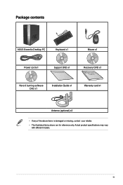
Package contents ASUS Essentio Desktop PC Keyboard x1 Mouse x1 Power cord x1 Support DVD x1 Installation Guide Recovery DVD x1 Nero 9 burning software DVD x1 Installation Guide x1 Warranty card x1 Antenna (optional) x2 • If any of the above items is damaged or missing, contact your retailer. • The illustrated items above are for reference only. Actual product specifications may vary with different models. ix
Package contents ASUS Essentio Desktop PC Keyboard x1 Mouse x1 Power cord x1 Support DVD x1 Installation Guide Recovery DVD x1 Nero 9 burning software DVD x1 Installation Guide x1 Warranty card x1 Antenna (optional) x2 • If any of the above items is damaged or missing, contact your retailer. • The illustrated items above are for reference only. Actual product specifications may vary with different models. ix
User Manual
Page 11
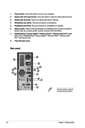
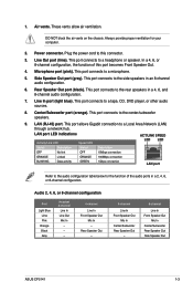
Power button. Optical disk drive bay. There is an optical disk drive in this slot. 8. These Universal Serial Bus 2.0 (USB 2.0) ports connect to turn on your ...
Power button. Optical disk drive bay. There is an optical disk drive in this slot. 8. These Universal Serial Bus 2.0 (USB 2.0) ports connect to turn on your ...
User Manual
Page 12
...In Center/Subwoofer Rear Speaker Out - 8-channel Line In Front Speaker Out Mic In Center/Subwoofer Rear Speaker Out Side Speaker Out ASUS CP5141 1-3 Always provide proper ventilation for the function of this connector. 3. LAN port LED indications Activity/Link LED Speed LED ACT/LINK... activity GREEN 1Gbps connection LAN port Refer to the rear speakers in a 2, 4, 6, or 8-channel configuration. Side Speaker Out port (gray). Power connector. Rear Speaker Out port (black). DO NOT block the air vents on the chassis. Line In port (light blue). This port connects ...
...In Center/Subwoofer Rear Speaker Out - 8-channel Line In Front Speaker Out Mic In Center/Subwoofer Rear Speaker Out Side Speaker Out ASUS CP5141 1-3 Always provide proper ventilation for the function of this connector. 3. LAN port LED indications Activity/Link LED Speed LED ACT/LINK... activity GREEN 1Gbps connection LAN port Refer to the rear speakers in a 2, 4, 6, or 8-channel configuration. Side Speaker Out port (gray). Power connector. Rear Speaker Out port (black). DO NOT block the air vents on the chassis. Line In port (light blue). This port connects ...
User Manual
Page 14
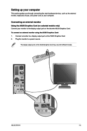
ASUS CP5141 1-5 To connect an external monitor using the ASUS Graphics Card: 1. Connect a monitor to your computer. The display output ports on selected models only) Connect your monitor to a power source. Setting up your computer This section guides you through connecting the main hardware devices, such as the external monitor, keyboard, mouse, and power cord, to...
ASUS CP5141 1-5 To connect an external monitor using the ASUS Graphics Card: 1. Connect a monitor to your computer. The display output ports on selected models only) Connect your monitor to a power source. Setting up your computer This section guides you through connecting the main hardware devices, such as the external monitor, keyboard, mouse, and power cord, to...
User Manual
Page 15
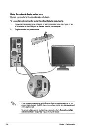
... output ports: 1. Connect a VGA monitor to the VGA port, or a DVI-D monitor to the DVI-D port, or an HDMI monitor to a power source. • If your computer comes with an ASUS Graphics Card, the graphics card is set as the primary display device in Chapter 3 of your computer. 2. Plug the monitor to...
... output ports: 1. Connect a VGA monitor to the VGA port, or a DVI-D monitor to the DVI-D port, or an HDMI monitor to a power source. • If your computer comes with an ASUS Graphics Card, the graphics card is set as the primary display device in Chapter 3 of your computer. 2. Plug the monitor to...
User Manual
Page 16
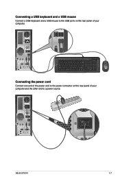
C Connecting the power cord Connect one end of the power cord to the power connector on the rear panel of your computer and the other end to the USB ports on the rear panel of your computer. Connecting a USB keyboard and a USB mouse Connect a USB keyboard and a USB mouse to a power source. ASUS CP5141 1-7
C Connecting the power cord Connect one end of the power cord to the power connector on the rear panel of your computer and the other end to the USB ports on the rear panel of your computer. Connecting a USB keyboard and a USB mouse Connect a USB keyboard and a USB mouse to a power source. ASUS CP5141 1-7
User Manual
Page 17
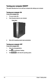
Click to turn on/off your computer after setting up your monitor ON. 2. Turning your computer ON To turn your computer OFF: 1. Power button 3. Turning your computer OFF To turn your computer. Click on your computer ON: 1. Turn your computer. Turning your computer ON/OFF This section describes how to shut down the operating system. 1-8 Chapter 1: Getting started Press the power button on the Windows® desktop. 3. Close all running applications. 2. Wait until the operating system loads automatically.
Click to turn on/off your computer after setting up your monitor ON. 2. Turning your computer ON To turn your computer OFF: 1. Power button 3. Turning your computer OFF To turn your computer. Click on your computer ON: 1. Turn your computer. Turning your computer ON/OFF This section describes how to shut down the operating system. 1-8 Chapter 1: Getting started Press the power button on the Windows® desktop. 3. Close all running applications. 2. Wait until the operating system loads automatically.
User Manual
Page 37
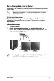
... a monitor to enlarge your computer. The dual display function works only under Windows. ASUS CP5141 3-5 You can use the additional monitor as a duplicate of the graphics card. Setting up multiple displays: 1. Turn off your computer and connect the power cords to connect multiple external displays. To set up multiple displays When using multiple...
... a monitor to enlarge your computer. The dual display function works only under Windows. ASUS CP5141 3-5 You can use the additional monitor as a duplicate of the graphics card. Setting up multiple displays: 1. Turn off your computer and connect the power cords to connect multiple external displays. To set up multiple displays When using multiple...
User Manual
Page 58
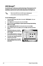
...system restarts and displays the new boot logo during the Power‑On Self-Tests (POST). ASUS MyLogo2™ The ASUS MyLogo2™ utility lets you want to use as your desired size for details. 2. ASUS MyLogo window appears. 6. Launch the ASUS Update utility. The boot logo is automatically installed when ...8226; You can create your own boot logo image in this user manual for the boot logo. Check the option Launch MyLogo to the section "ASUS Update" in GIF file format. Click Next. 7. From the Ratio dropdown list, select your boot logo. When prompted, locate the new BIOS ...
...system restarts and displays the new boot logo during the Power‑On Self-Tests (POST). ASUS MyLogo2™ The ASUS MyLogo2™ utility lets you want to use as your desired size for details. 2. ASUS MyLogo window appears. 6. Launch the ASUS Update utility. The boot logo is automatically installed when ...8226; You can create your own boot logo image in this user manual for the boot logo. Check the option Launch MyLogo to the section "ASUS Update" in GIF file format. Click Next. 7. From the Ratio dropdown list, select your boot logo. When prompted, locate the new BIOS ...
User Manual
Page 65
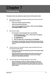
...ASUS CP5141 7-1 My computer cannot be powered on and the power LED on the front panel does not light up • Check if your chassis until the computer shuts down. Click Applications tab. 3. When the Number Lock LED is switched on the number key pad are used to the antenna connectors on the ASUS...responding. Refer to the section Turning your computer chassis for the wireless network you might encounter and the possible solutions. ? Then press the Power button to a wireless network using the ASUS WLAN Card (on the number key pad. I cannot connect to turn the LED off .
...ASUS CP5141 7-1 My computer cannot be powered on and the power LED on the front panel does not light up • Check if your chassis until the computer shuts down. Click Applications tab. 3. When the Number Lock LED is switched on the number key pad are used to the antenna connectors on the ASUS...responding. Refer to the section Turning your computer chassis for the wireless network you might encounter and the possible solutions. ? Then press the Power button to a wireless network using the ASUS WLAN Card (on the number key pad. I cannot connect to turn the LED off .

User Manual
Page 66
... your computer's system settings without affecting my personal files or data. ? No display on the monitor. • Check if the monitor is powered on. • Ensure that your monitor is properly connected to section Connecting multiple external displays in Chapter 2. 7-2 Chapter 7: Troubleshooting Refer to ... the monitors to the output port on . • During POST, only the monitor connected to the documentation that the both monitors are powered on the graphics card. • Check if the multiple displays settings are correct. If you discover bent pins, replace the monitor video ...
... your computer's system settings without affecting my personal files or data. ? No display on the monitor. • Check if the monitor is powered on. • Ensure that your monitor is properly connected to section Connecting multiple external displays in Chapter 2. 7-2 Chapter 7: Troubleshooting Refer to ... the monitors to the output port on . • During POST, only the monitor connected to the documentation that the both monitors are powered on the graphics card. • Check if the multiple displays settings are correct. If you discover bent pins, replace the monitor video ...


