
CUSI-FX User Manual
Page 2
...in the manual revision number. USER'S NOTICE No part of this manual may or may be reproduced, transmitted, transcribed, stored in a retrieval system, or translated into any language in any form or by any of the product is defaced or missing. The product name and revision number are...by the third digit in writing by the digit before and after the period of Adobe Systems Incorporated. For previous or updated manuals, BIOS, drivers, or product release information, contact ASUS at http://www.asus.com.tw or through any means, except documentation kept by the purchaser for each product...
...in the manual revision number. USER'S NOTICE No part of this manual may or may be reproduced, transmitted, transcribed, stored in a retrieval system, or translated into any language in any form or by any of the product is defaced or missing. The product name and revision number are...by the third digit in writing by the digit before and after the period of Adobe Systems Incorporated. For previous or updated manuals, BIOS, drivers, or product release information, contact ASUS at http://www.asus.com.tw or through any means, except documentation kept by the purchaser for each product...

CUSI-FX User Manual
Page 4
... 4.1 Managing and Updating Your BIOS 41 4.1.1 Upon First Use of the Computer System 41 4.1.2 Updating BIOS Procedures 42 4.2 BIOS Setup Program 45 4.2.1 BIOS Menu Bar 46 4.2.2 Legend Bar 46 4.3 Main Menu 48 4.3.1 Primary & Secondary Master/Slave 49 4.3.2 Keyboard Features 52 4 ASUS CUSI-FX User's Manual INTRODUCTION 7 1.1 How This Manual Is Organized 7 1.2 Item...
... 4.1 Managing and Updating Your BIOS 41 4.1.1 Upon First Use of the Computer System 41 4.1.2 Updating BIOS Procedures 42 4.2 BIOS Setup Program 45 4.2.1 BIOS Menu Bar 46 4.2.2 Legend Bar 46 4.3 Main Menu 48 4.3.1 Primary & Secondary Master/Slave 49 4.3.2 Keyboard Features 52 4 ASUS CUSI-FX User's Manual INTRODUCTION 7 1.1 How This Manual Is Organized 7 1.2 Item...

CUSI-FX User Manual
Page 5
SOFTWARE SETUP 75 5.1 Install Operating System 75 5.2 Start Windows 75 5.3 CUSI-FX Motherboard Support CD 75 6. SOFTWARE REFERENCE 77 6.1 Display Properties 77 6.2 ASUS PC Probe 81 6.3 ASUS Update 86 6.4 CyberLink PowerPlayer SE 87 6.5 CyberLink PowerDVD 89 6.6 CyberLink VideoLive Mail 89 7. CONTENTS 4.4 Advanced Menu 54 4.4.1 Chip Configuration 57 4.4.2 I/O Device Configuration 60 4.4.3... 64 4.5 Power Menu 65 4.5.1 Power Up Control 67 4.5.2 Hardware Monitor 69 4.6 Boot Menu 70 4.7 Exit Menu 72 5. APPENDIX 91 7.1 Glossary 91 INDEX 95 ASUS CUSI-FX User's Manual 5
SOFTWARE SETUP 75 5.1 Install Operating System 75 5.2 Start Windows 75 5.3 CUSI-FX Motherboard Support CD 75 6. SOFTWARE REFERENCE 77 6.1 Display Properties 77 6.2 ASUS PC Probe 81 6.3 ASUS Update 86 6.4 CyberLink PowerPlayer SE 87 6.5 CyberLink PowerDVD 89 6.6 CyberLink VideoLive Mail 89 7. CONTENTS 4.4 Advanced Menu 54 4.4.1 Chip Configuration 57 4.4.2 I/O Device Configuration 60 4.4.3... 64 4.5 Power Menu 65 4.5.1 Power Up Control 67 4.5.2 Hardware Monitor 69 4.6 Boot Menu 70 4.7 Exit Menu 72 5. APPENDIX 91 7.1 Glossary 91 INDEX 95 ASUS CUSI-FX User's Manual 5

CUSI-FX User Manual
Page 8
.... • PC Health Monitoring: Provides an easy way to examine and manage system status information, such as CPU and systerm voltages, temperatures, and fan status through the onboard hardware ITE 8705 and the bundled ASUS PC Probe. • AMR Slot: Audio Modem Riser slot supports a very... affordable audio and/or modem riser card. • Legacy Free: Provides two 32-bit PCI (Asynchronous PCI 2.2 compliant) with no ISA, eliminating bottlenecks and system memory management issues. Supports ...
.... • PC Health Monitoring: Provides an easy way to examine and manage system status information, such as CPU and systerm voltages, temperatures, and fan status through the onboard hardware ITE 8705 and the bundled ASUS PC Probe. • AMR Slot: Audio Modem Riser slot supports a very... affordable audio and/or modem riser card. • Legacy Free: Provides two 32-bit PCI (Asynchronous PCI 2.2 compliant) with no ISA, eliminating bottlenecks and system memory management issues. Supports ...

CUSI-FX User Manual
Page 10
...Windows 95/NT and later. FEATURES 2.1.3 Performance • UltraPerformance: Onboard IDE Bus Master controller with existing DMA devices and systems so there is also implemented on the following high-level goals: support for Plug and Play compatibility and power management for configuring... and managing all the energy saving standards. The new PC 99 requirements for systems and components are based on all ASUS smart series motherboards. Color-coded connectors and descriptive icons make identification easy as Windows 98/2000/Millenium, must...
...Windows 95/NT and later. FEATURES 2.1.3 Performance • UltraPerformance: Onboard IDE Bus Master controller with existing DMA devices and systems so there is also implemented on the following high-level goals: support for Plug and Play compatibility and power management for configuring... and managing all the energy saving standards. The new PC 99 requirements for systems and components are based on all ASUS smart series motherboards. Color-coded connectors and descriptive icons make identification easy as Windows 98/2000/Millenium, must...

CUSI-FX User Manual
Page 11
... modem. With this motherboard supports processor thermal sensing and auto-protection. • Voltage Monitoring and Alert: System voltage levels are more critical for more memory and hard drive space to critical motherboard components. The onboard hardware ASUS ASIC in the world. • Message LED (requires ACPI OS support): Message LEDs now act...
... modem. With this motherboard supports processor thermal sensing and auto-protection. • Voltage Monitoring and Alert: System voltage levels are more critical for more memory and hard drive space to critical motherboard components. The onboard hardware ASUS ASIC in the world. • Message LED (requires ACPI OS support): Message LEDs now act...

CUSI-FX User Manual
Page 12
... 12 Main Memory Maximum 1GB support 2 DIMM Sockets 4 PC100/133 SDRAM and VCM SDRAM support Expansion Slots 2 PCI Slots 14 1 PCI/AMR Share Slot 11 System I/O 2 IDE Connectors (UltraDMA/66 support 6 1 Floppy Disk Drive Connector 7 2 USB Headers (supports 3 USB ports 8 1 Serial COM2 Header 10 2 USB Port Connectors Bottom...RJ45) Connector (optional Top) 20 Wake-On-LAN Connector 9 Wake-On-Ring Connector 1 Power ATX Power Supply Connector 5 Form Factor FlexATX 12 ASUS CUSI-FX User's Manual Location Processor Support Socket 370 for locations. 2. FEATURES MB Components 2.
... 12 Main Memory Maximum 1GB support 2 DIMM Sockets 4 PC100/133 SDRAM and VCM SDRAM support Expansion Slots 2 PCI Slots 14 1 PCI/AMR Share Slot 11 System I/O 2 IDE Connectors (UltraDMA/66 support 6 1 Floppy Disk Drive Connector 7 2 USB Headers (supports 3 USB ports 8 1 Serial COM2 Header 10 2 USB Port Connectors Bottom...RJ45) Connector (optional Top) 20 Wake-On-LAN Connector 9 Wake-On-Ring Connector 1 Power ATX Power Supply Connector 5 Form Factor FlexATX 12 ASUS CUSI-FX User's Manual Location Processor Support Socket 370 for locations. 2. FEATURES MB Components 2.

CUSI-FX User Manual
Page 15
... (10-1 pins, 5-1 pins) 17) CD1, AUX, MODEM p.34 Internal Audio Connectors (Two 4 pins) (optional) 18) AFPANEL p.35 ASUS iPanel Connector (12-1 pins) 19) AAPANEL p.35 ASUS iPanel Audio Connector (12-1 pins) 20) SPEAKER (PANEL) p.37 System Warning Speaker Connector (4 pins) 21) KLOCK (PANEL) p.37 Keyboard Lock Switch Lead (2 pins) 22) PWRLED (PANEL) p.37...
... (10-1 pins, 5-1 pins) 17) CD1, AUX, MODEM p.34 Internal Audio Connectors (Two 4 pins) (optional) 18) AFPANEL p.35 ASUS iPanel Connector (12-1 pins) 19) AAPANEL p.35 ASUS iPanel Audio Connector (12-1 pins) 20) SPEAKER (PANEL) p.37 System Warning Speaker Connector (4 pins) 21) KLOCK (PANEL) p.37 Keyboard Lock Switch Lead (2 pins) 22) PWRLED (PANEL) p.37...

CUSI-FX User Manual
Page 16
To protect them against damage from the system. 5. Ensure that came with the component whenever the components are separated from static electricity, you should follow some precautions whenever you work on your computer ...! H/W SETUP Motherboard Settings 01 ® JP3 JP1 JP2 JP0 3 2 1 CUSI-FX CUSI-FX JumperFree™ Mode Setting JEN Jumperless Mode Jumper Mode 12 12 16 ASUS CUSI-FX User's Manual Unplug your computer. 1.
To protect them against damage from the system. 5. Ensure that came with the component whenever the components are separated from static electricity, you should follow some precautions whenever you work on your computer ...! H/W SETUP Motherboard Settings 01 ® JP3 JP1 JP2 JP0 3 2 1 CUSI-FX CUSI-FX JumperFree™ Mode Setting JEN Jumperless Mode Jumper Mode 12 12 16 ASUS CUSI-FX User's Manual Unplug your computer. 1.

CUSI-FX User Manual
Page 17
The default is set to your system.This feature requires an ATX power supply that is, either both must be set these to Enable. 2. NOTES: 1. Setting USBPWR0/USBPWR1 Enable [1-2] Disable [2-3] (default) 01 ... ATX power supply. These settings must be set in 4.5.1 Power Up Control. that can supply at least 2A on the +5VSB lead. H/W SETUP Motherboard Settings ASUS CUSI-FX User's Manual 17 3. HARDWARE SETUP 2) USB Device Wake Up (USBPWR0, USBPWR1) These jumpers allow you set to Disable or both to Enable and...
The default is set to your system.This feature requires an ATX power supply that is, either both must be set these to Enable. 2. NOTES: 1. Setting USBPWR0/USBPWR1 Enable [1-2] Disable [2-3] (default) 01 ... ATX power supply. These settings must be set in 4.5.1 Power Up Control. that can supply at least 2A on the +5VSB lead. H/W SETUP Motherboard Settings ASUS CUSI-FX User's Manual 17 3. HARDWARE SETUP 2) USB Device Wake Up (USBPWR0, USBPWR1) These jumpers allow you set to Disable or both to Enable and...

CUSI-FX User Manual
Page 20
...tended Data Output) chips. • BIOS shows SDRAM memory on the motherboard. double-sided come in 32, 64, 128, 256, 512MB. 20 ASUS CUSI-FX User's Manual Memory speed setup is required after adding or removing memory. This motherboard uses only Dual Inline Memory Modules (DIMMs). This motherboard...DIMM1 (Rows 0&1) DIMM2 (Rows 2&3) 168-pin DIMM SDRAM 16, 32, 64, 128, 256, 512MB SDRAM 16, 32, 64, 128, 256, 512MB Total System Memory (Max 1GB) Total Memory x1 x1 = 3.5.1 General DIMM Notes • This motherboard supports SPD (Serial Presence Detect) DIMMs. This is the memory of choice...
...tended Data Output) chips. • BIOS shows SDRAM memory on the motherboard. double-sided come in 32, 64, 128, 256, 512MB. 20 ASUS CUSI-FX User's Manual Memory speed setup is required after adding or removing memory. This motherboard uses only Dual Inline Memory Modules (DIMMs). This motherboard...DIMM1 (Rows 0&1) DIMM2 (Rows 2&3) 168-pin DIMM SDRAM 16, 32, 64, 128, 256, 512MB SDRAM 16, 32, 64, 128, 256, 512MB Total System Memory (Max 1GB) Total Memory x1 x1 = 3.5.1 General DIMM Notes • This motherboard supports SPD (Serial Presence Detect) DIMMs. This is the memory of choice...

CUSI-FX User Manual
Page 21
...3.5.2 DIMM Memory Installation Insert the module(s) as shown. You must be 3.3V Unbuffered for this motherboard. This motherboard supports four clock signals. ASUS CUSI-FX User's Manual 21 DIMM modules are different on both sides. To determine the DIMM type, check the notches on the DIMMs (see...CUSI-FX CUSI-FX 168-Pin DIMM Sockets 60 Pins 20 Pins The DIMMs must ask your retailer the correct DIMM type before purchasing. H/W SETUP System Memory 3. SIMM modules have the same pin contact on either side of pins are longer and have a higher pin density. ® 3. Because...
...3.5.2 DIMM Memory Installation Insert the module(s) as shown. You must be 3.3V Unbuffered for this motherboard. This motherboard supports four clock signals. ASUS CUSI-FX User's Manual 21 DIMM modules are different on both sides. To determine the DIMM type, check the notches on the DIMMs (see...CUSI-FX CUSI-FX 168-Pin DIMM Sockets 60 Pins 20 Pins The DIMMs must ask your retailer the correct DIMM type before purchasing. H/W SETUP System Memory 3. SIMM modules have the same pin contact on either side of pins are longer and have a higher pin density. ® 3. Because...

CUSI-FX User Manual
Page 22
... on unlocked processors) for reference only; H/W SETUP CPU ® Notch Celeron CUSI-FX CUSI-FX Socket 370 Pentium III Gold Arrow 22 ASUS CUSI-FX User's Manual You may occur to set the correct Bus Frequency and Multiple (frequency multiple setting is working. you turn off your...Socket 370 CPU (Top) Socket 370 CPU (Bottom) 01 3. Be sure that there is for your system and remove its cover. The notched corner should have a CPU fan that your system. The picture is sufficient air circulation across the processor's heatsink by first pulling the lever sideways away from...
... on unlocked processors) for reference only; H/W SETUP CPU ® Notch Celeron CUSI-FX CUSI-FX Socket 370 Pentium III Gold Arrow 22 ASUS CUSI-FX User's Manual You may occur to set the correct Bus Frequency and Multiple (frequency multiple setting is working. you turn off your...Socket 370 CPU (Top) Socket 370 CPU (Bottom) 01 3. Be sure that there is for your system and remove its cover. The notched corner should have a CPU fan that your system. The picture is sufficient air circulation across the processor's heatsink by first pulling the lever sideways away from...

CUSI-FX User Manual
Page 23
HARDWARE SETUP 3.7 Expansion Cards WARNING! Secure the card on the slot you removed above. 5. H/W SETUP Expansion Cards ASUS CUSI-FX User's Manual 23 Keep the bracket for Expansion Cards Some expansion cards need an IRQ to operate. In a standard design, there are 16 .... 6. Generally, an IRQ must be used . If your power supply when adding or removing expansion cards or other system components. Failure to do so may cause severe damage to both your computer system's cover and the bracket plate on the slot with the screw you intend to one use , leaving 6 IRQs free...
HARDWARE SETUP 3.7 Expansion Cards WARNING! Secure the card on the slot you removed above. 5. H/W SETUP Expansion Cards ASUS CUSI-FX User's Manual 23 Keep the bracket for Expansion Cards Some expansion cards need an IRQ to operate. In a standard design, there are 16 .... 6. Generally, an IRQ must be used . If your power supply when adding or removing expansion cards or other system components. Failure to do so may cause severe damage to both your computer system's cover and the bracket plate on the slot with the screw you intend to one use , leaving 6 IRQs free...

CUSI-FX User Manual
Page 24
... for standard PC devices. not shared - - shared - - - - shared - INT-D - - - - IMPORTANT: If using PCI cards on shared slots, make the system unstable or cards inoperable. 24 ASUS CUSI-FX User's Manual HARDWARE SETUP The following table: PCI slot 1 PCI slot 2 Onboard VGA Onboard LAN Onboard USB controller Onboard Audio AMR INT-A shared - ...
... for standard PC devices. not shared - - shared - - - - shared - INT-D - - - - IMPORTANT: If using PCI cards on shared slots, make the system unstable or cards inoperable. 24 ASUS CUSI-FX User's Manual HARDWARE SETUP The following table: PCI slot 1 PCI slot 2 Onboard VGA Onboard LAN Onboard USB controller Onboard Audio AMR INT-A shared - ...

CUSI-FX User Manual
Page 25
CUSI-FX CUSI-FX Audio Modem Riser (AMR) Connector 01 ® 3. HARDWARE SETUP 3.7.3 Audio Modem Riser (AMR) Slot This connector supports a specially designed audio and/or modem card called an AMR. Main processing is not included with this motherboard. This provides an upgradeable audio and/or modem solution at an incredibly low cost. H/W SETUP Expansion Cards ASUS CUSI-FX User's Manual 25 3. The motherboard's onboard CODEC (optional) must be disabled when using an AMR. NOTE: An AMR is done through software and controlled by the motherboard's system chipset.
CUSI-FX CUSI-FX Audio Modem Riser (AMR) Connector 01 ® 3. HARDWARE SETUP 3.7.3 Audio Modem Riser (AMR) Slot This connector supports a specially designed audio and/or modem card called an AMR. Main processing is not included with this motherboard. This provides an upgradeable audio and/or modem solution at an incredibly low cost. H/W SETUP Expansion Cards ASUS CUSI-FX User's Manual 25 3. The motherboard's onboard CODEC (optional) must be disabled when using an AMR. NOTE: An AMR is done through software and controlled by the motherboard's system chipset.
CUSI-FX User Manual
Page 26
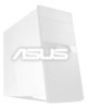
... pins are clearly distinguished from the first connector. 1) PS/2 Mouse Connector (Green 6-pin PS2KBMS) The system will direct IRQ12 to the PS/2 mouse if one is for connectors or power sources. PS/2 Keyboard (6-pin female) 26 ASUS CUSI-FX User's Manual Check the connectors before installation because there may use IRQ12. H/W SETUP...
... pins are clearly distinguished from the first connector. 1) PS/2 Mouse Connector (Green 6-pin PS2KBMS) The system will direct IRQ12 to the PS/2 mouse if one is for connectors or power sources. PS/2 Keyboard (6-pin female) 26 ASUS CUSI-FX User's Manual Check the connectors before installation because there may use IRQ12. H/W SETUP...
CUSI-FX User Manual
Page 30
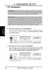
... hard disk ribbon cable. If you install two hard disks, you must use a 40-pin 80-conductor IDE cable for 66MBytes/s transfer rates. one operating system on an IDE drive and another for the jumper settings. You may configure two hard disks to your UltraDMA/66 master device. tion when using...
... hard disk ribbon cable. If you install two hard disks, you must use a 40-pin 80-conductor IDE cable for 66MBytes/s transfer rates. one operating system on an IDE drive and another for the jumper settings. You may configure two hard disks to your UltraDMA/66 master device. tion when using...

CUSI-FX User Manual
Page 32
... or signal is enabled (see 4.4.3 Power Management) and that your system has an ATX power supply with at least 720mA +5 volt standby power CUSI-FX WOL_CON +5 Volt Standby PME Ground CUSI-FX Wake-On-LAN Connector 32 ASUS CUSI-FX User's Manual IMPORTANT: This feature requires that Wake-On...-Lan features are enabled (see 4.5.1 Power Up Control) and that your system has an ATX power supply with at least 720mA +5V standby power. ...
... or signal is enabled (see 4.4.3 Power Management) and that your system has an ATX power supply with at least 720mA +5 volt standby power CUSI-FX WOL_CON +5 Volt Standby PME Ground CUSI-FX Wake-On-LAN Connector 32 ASUS CUSI-FX User's Manual IMPORTANT: This feature requires that Wake-On...-Lan features are enabled (see 4.5.1 Power Up Control) and that your system has an ATX power supply with at least 720mA +5V standby power. ...

CUSI-FX User Manual
Page 36
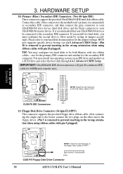
CUSI-FX System Panel Connectors 36 ASUS CUSI-FX User's Manual 3. HARDWARE SETUP The following is for items 20-26 01 Keyboard Lock Speaker Power LED Connector +5 V PLED Keylock Ground +5V Ground Ground Speaker ® +5 V MLED ExtSMI# Ground PWR Ground Reset Ground Reset SW CUSI-FX Message LED ATX Power SMI Lead Switch* * Requires an ATX power supply.
CUSI-FX System Panel Connectors 36 ASUS CUSI-FX User's Manual 3. HARDWARE SETUP The following is for items 20-26 01 Keyboard Lock Speaker Power LED Connector +5 V PLED Keylock Ground +5V Ground Ground Speaker ® +5 V MLED ExtSMI# Ground PWR Ground Reset Ground Reset SW CUSI-FX Message LED ATX Power SMI Lead Switch* * Requires an ATX power supply.

