
CUW-RM User Manual
Page 8
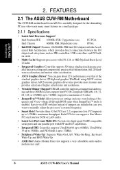
...33MB/s, and PIO Mode 4 up to 17MB/s. • Peripheral Wake-Up! Audio Modem Riser slot supports a very affordable audio and/or modem riser card. 8 ASUS CUW-RM User's Manual Supports Wake-On-LAN, Wake-On-Ring, Keyboard Wake-Up, and BIOS Wake-Up. • AMR Slot! Intel Pentium III E 100MHz... voltage all through BIOS setup when JumperFree™ mode is carefully designed for the demanding PC user who wants many smart features in case you want to 133MB/s maximum throughput. Allows processor settings and easy overclocking of 4 sides) • JumperFree™ Mode! FEATURES 2.1 The...
...33MB/s, and PIO Mode 4 up to 17MB/s. • Peripheral Wake-Up! Audio Modem Riser slot supports a very affordable audio and/or modem riser card. 8 ASUS CUW-RM User's Manual Supports Wake-On-LAN, Wake-On-Ring, Keyboard Wake-Up, and BIOS Wake-Up. • AMR Slot! Intel Pentium III E 100MHz... voltage all through BIOS setup when JumperFree™ mode is carefully designed for the demanding PC user who wants many smart features in case you want to 133MB/s maximum throughput. Allows processor settings and easy overclocking of 4 sides) • JumperFree™ Mode! FEATURES 2.1 The...
CUW-RM User Manual
Page 17
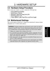
... Settings This section explains in detail how to touch the IC chips, leads or connectors, or other components. 4. H/W SETUP Motherboard Settings ASUS CUW-RM User's Manual 17 Use a grounded wrist strap before handling computer components. To protect them against damage from the system. 3. ... HARDWARE SETUP 3.3 Hardware Setup Procedure Before using your hands to a safely grounded object or to a metal object, such as the power supply case. 3. If you work on your computer when working on the inside. 2. 3. WARNING! Place components on a grounded antistatic pad or on ...
... Settings This section explains in detail how to touch the IC chips, leads or connectors, or other components. 4. H/W SETUP Motherboard Settings ASUS CUW-RM User's Manual 17 Use a grounded wrist strap before handling computer components. To protect them against damage from the system. 3. ... HARDWARE SETUP 3.3 Hardware Setup Procedure Before using your hands to a safely grounded object or to a metal object, such as the power supply case. 3. If you work on your computer when working on the inside. 2. 3. WARNING! Place components on a grounded antistatic pad or on ...
CUW-RM User Manual
Page 20
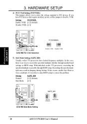
... 3 VSB Disable 3 VSB 5) Safe Mode Setting (SAFE_MD) Usually socket 370 processors have PCI devices that require auxiliary power, set this case, there is possible through motherboard settings or BIOS setup. Setting PCI3VSEL Enable 3VSB [1-2] (default) Disable 3VSB [2-3] 3. Setting Normal Safe Mode...SAFE_MD [1-2] (default) [2-3] CUW-RM ® CUW-RM Safe Mode Setting SAFE_MD 3 2 1 Normal (Default) 3 2 1 Safe Mode 20 ASUS CUW-RM User's Manual If you to select the voltage supplied to correct the problem. With unlocked socket 370 processors, exceeding the specified multiple is...
... 3 VSB Disable 3 VSB 5) Safe Mode Setting (SAFE_MD) Usually socket 370 processors have PCI devices that require auxiliary power, set this case, there is possible through motherboard settings or BIOS setup. Setting PCI3VSEL Enable 3VSB [1-2] (default) Disable 3VSB [2-3] 3. Setting Normal Safe Mode...SAFE_MD [1-2] (default) [2-3] CUW-RM ® CUW-RM Safe Mode Setting SAFE_MD 3 2 1 Normal (Default) 3 2 1 Safe Mode 20 ASUS CUW-RM User's Manual If you to select the voltage supplied to correct the problem. With unlocked socket 370 processors, exceeding the specified multiple is...
CUW-RM User Manual
Page 26
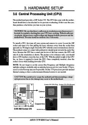
...to the motherboard. The notched corner (or corner with the motherboard should point towards the end of the CPU fan, no force is not the case, then purchase a fan before you should have a fan attached to it by regularly checking that covers the face of the four corners, the ... its cover. CAUTION! Socket 370 CPU (Top) Socket 370 CPU (Bottom) Celeron CUW-RM ® Notch Coppermine CUW-RM Socket 370 Gold Arrow 26 ASUS CUW-RM User's Manual HARDWARE SETUP 3.6 Central Processing Unit (CPU) The motherboard provides a ZIF Socket 370. WARNING! Locate the ZIF socket and open it...
...to the motherboard. The notched corner (or corner with the motherboard should point towards the end of the CPU fan, no force is not the case, then purchase a fan before you should have a fan attached to it by regularly checking that covers the face of the four corners, the ... its cover. CAUTION! Socket 370 CPU (Top) Socket 370 CPU (Bottom) Celeron CUW-RM ® Notch Coppermine CUW-RM Socket 370 Gold Arrow 26 ASUS CUW-RM User's Manual HARDWARE SETUP 3.6 Central Processing Unit (CPU) The motherboard provides a ZIF Socket 370. WARNING! Locate the ZIF socket and open it...
CUW-RM User Manual
Page 36
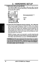
... 14) Chassis,CPU,&PowerSupplyFanConnectors(3-pinCHA_,CPU_,PWR_FAN) These connectors support cooling fans of 350mA (4.2 Watts) or less. SOFTWARE REFERENCE). H/W SETUP Connectors 36 ASUS CUW-RM User's Manual These are incorrectly used only by devices connected to the Primary or Secondary IDE connectors will overheat if there is to... on the fan manufacturer, the wiring and plug may occur to the cabinet's IDE activity LED. CUW-RM ® TIP: If the case-mounted LED does not light, try reversing the 2-pin plug. The red wire should be positive, while the black should be used . 3.
... 14) Chassis,CPU,&PowerSupplyFanConnectors(3-pinCHA_,CPU_,PWR_FAN) These connectors support cooling fans of 350mA (4.2 Watts) or less. SOFTWARE REFERENCE). H/W SETUP Connectors 36 ASUS CUW-RM User's Manual These are incorrectly used only by devices connected to the Primary or Secondary IDE connectors will overheat if there is to... on the fan manufacturer, the wiring and plug may occur to the cabinet's IDE activity LED. CUW-RM ® TIP: If the case-mounted LED does not light, try reversing the 2-pin plug. The red wire should be positive, while the black should be used . 3.
CUW-RM User Manual
Page 37
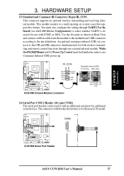
... five pins as shown in Back View and connect a ribbon cable from the module to the motherboard's SIR connector according to a small opening on system cases that support this feature. CUW-RM ® IR_CON IRTX GND IRRX (NC) +5V CIR+5V CIRRX GND (NC) Standard Infrared (SIR) Front View Back View... KB/Mouse in order to add an additional serial port for the non-LCD model. COM2 CUW-RM ® Pin 1 CUW-RM Serial Port Header ASUS CUW-RM User's Manual 37 H/W SETUP Connectors 3.
... five pins as shown in Back View and connect a ribbon cable from the module to the motherboard's SIR connector according to a small opening on system cases that support this feature. CUW-RM ® IR_CON IRTX GND IRRX (NC) +5V CIR+5V CIRRX GND (NC) Standard Infrared (SIR) Front View Back View... KB/Mouse in order to add an additional serial port for the non-LCD model. COM2 CUW-RM ® Pin 1 CUW-RM Serial Port Header ASUS CUW-RM User's Manual 37 H/W SETUP Connectors 3.
CUW-RM User Manual
Page 42
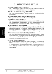
... Pressing the button once will remain lit when there is no signal and blink when there is controlled by a momentary switch connected to the case-mounted suspend switch. 30) Message LED Lead (2-pin LED) This indicates whether a message has been received from a fax/modem. This 2-pin... connector connects to this lead. H/W SETUP Connectors 42 ASUS CUW-RM User's Manual HARDWARE SETUP 24) System Power LED Lead (3-1 pin PLED) This 3-1 pin connector connects the system power LED, which lights ...
... Pressing the button once will remain lit when there is no signal and blink when there is controlled by a momentary switch connected to the case-mounted suspend switch. 30) Message LED Lead (2-pin LED) This indicates whether a message has been received from a fax/modem. This 2-pin... connector connects to this lead. H/W SETUP Connectors 42 ASUS CUW-RM User's Manual HARDWARE SETUP 24) System Power LED Lead (3-1 pin PLED) This 3-1 pin connector connects the system power LED, which lights ...
CUW-RM User Manual
Page 43
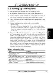
... (starting with ). 3. The power LED on the front panel of the system case will appear on tests. While the tests are running at a lower frequency ASUS CUW-RM User's Manual 43 After all switches are made, close the system case cover. 2. For ATX power supplies, the system LED will then run power-on... the system's if it has a power standby feature. Your monitor b. 3. Connect the power cord into the power supply located on the front of your system case according to switch on the power supply as well as press the ATX power switch on the back of the...
... (starting with ). 3. The power LED on the front panel of the system case will appear on tests. While the tests are running at a lower frequency ASUS CUW-RM User's Manual 43 After all switches are made, close the system case cover. 2. For ATX power supplies, the system LED will then run power-on... the system's if it has a power standby feature. Your monitor b. 3. Connect the power cord into the power supply located on the front of your system case according to switch on the power supply as well as press the ATX power switch on the back of the...
CUW-RM User Manual
Page 45
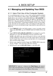
... Memory Writer utility (AFLASH.EXE) to a bootable floppy disk in the boot sequence. 4. Type FORMAT A:/S at the DOS prompt to the disk. 2. 4. ASUS CUW-RM User's Manual 45 Larger numbers represent a newer BIOS file. 1. BIOS SETUP 4.1 Managing and Updating Your BIOS 4.1.1 Upon First Use of your hard... drive. NOTE: BIOS setup must specify "Floppy" as the first item in case you boot from the floppy disk. In DOS mode, type A:\AFLASH to the programmable flash ROM on the upper lefthand corner of the Computer ...
... Memory Writer utility (AFLASH.EXE) to a bootable floppy disk in the boot sequence. 4. Type FORMAT A:/S at the DOS prompt to the disk. 2. 4. ASUS CUW-RM User's Manual 45 Larger numbers represent a newer BIOS file. 1. BIOS SETUP 4.1 Managing and Updating Your BIOS 4.1.1 Upon First Use of your hard... drive. NOTE: BIOS setup must specify "Floppy" as the first item in case you boot from the floppy disk. In DOS mode, type A:\AFLASH to the programmable flash ROM on the upper lefthand corner of the Computer ...

CUW-RM User Manual
Page 56
... this field and press . Language [English] This allows selection of the BIOS' displayed language. Type in the field for "Type:" are not case sensitive. The password is now set to all BIOS Setup program functions. Press and the password will appear. In other keys are ignored. The...A Note about Passwords The BIOS Setup program allows you enter a password using the legend keys to the Main menu. BIOS SETUP Main Menu 56 ASUS CUW-RM User's Manual The passwords control access to [Enabled]. for IDE CD-ROM drives [LS-120] - To set the passwords. Symbols and...
... this field and press . Language [English] This allows selection of the BIOS' displayed language. Type in the field for "Type:" are not case sensitive. The password is now set to all BIOS Setup program functions. Press and the password will appear. In other keys are ignored. The...A Note about Passwords The BIOS Setup program allows you enter a password using the legend keys to the Main menu. BIOS SETUP Main Menu 56 ASUS CUW-RM User's Manual The passwords control access to [Enabled]. for IDE CD-ROM drives [LS-120] - To set the passwords. Symbols and...
CUW-RM User Manual
Page 119
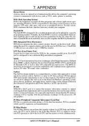
...OnNow is a special set of 57 new instructions based on the drive itself, eliminating the need for a separate adapter card (in the case for SCSI devices). PCI 2.1 supports concurrent PCI operation to allow the local CPU and bus master to 33MB/Sec transfer. IDE (Integrated ... and Pentium II (Klamath) CPU as well as other x86-compatible microprocessors. PCI is used by DOS for the processors, I/O and graphics. ASUS CUW-RM User's Manual 119 Since the contents of the Bus Masters. DOS is a comprehensive, system-wide approach to system performance. APPENDIX Glossary ...
...OnNow is a special set of 57 new instructions based on the drive itself, eliminating the need for a separate adapter card (in the case for SCSI devices). PCI 2.1 supports concurrent PCI operation to allow the local CPU and bus master to 33MB/Sec transfer. IDE (Integrated ... and Pentium II (Klamath) CPU as well as other x86-compatible microprocessors. PCI is used by DOS for the processors, I/O and graphics. ASUS CUW-RM User's Manual 119 Since the contents of the Bus Masters. DOS is a comprehensive, system-wide approach to system performance. APPENDIX Glossary ...


