CUW-RM User Manual
Page 4
...Use of the Computer System 45 4.1.2 Updating BIOS Procedures 46 4.2 BIOS Setup Program 49 4.2.1 BIOS Menu Bar 50 4.2.2 Legend Bar 50 4.3 Main Menu 52 4.3.1 Primary & Secondary Master/Slave 53 4.4 Advanced Menu 58 4.4.1 Chip Configuration 62 4.4.2 I/O Device Configuration 64 4.4.3 PCI Configuration 66 4.4.4 Shadow Configuration 69 4 ASUS CUW-RM User's Manual INTRODUCTION 7 1.1 How This Manual Is Organized 7 1.2 Item Checklist 7 2. HARDWARE SETUP 14 3.1 Motherboard Layout 14 3.2 Layout Contents 15 3.3 Hardware Setup Procedure 17 3.4 Motherboard Settings 17 3.5 System Memory...
...Use of the Computer System 45 4.1.2 Updating BIOS Procedures 46 4.2 BIOS Setup Program 49 4.2.1 BIOS Menu Bar 50 4.2.2 Legend Bar 50 4.3 Main Menu 52 4.3.1 Primary & Secondary Master/Slave 53 4.4 Advanced Menu 58 4.4.1 Chip Configuration 62 4.4.2 I/O Device Configuration 64 4.4.3 PCI Configuration 66 4.4.4 Shadow Configuration 69 4 ASUS CUW-RM User's Manual INTRODUCTION 7 1.1 How This Manual Is Organized 7 1.2 Item Checklist 7 2. HARDWARE SETUP 14 3.1 Motherboard Layout 14 3.2 Layout Contents 15 3.3 Hardware Setup Procedure 17 3.4 Motherboard Settings 17 3.5 System Memory...
CUW-RM User Manual
Page 7
... retailer. (1) ASUS Motherboard (1) 40-pin 80-conductor ribbon cable for internal UltraDMA/66 or UltraDMA/ 33 IDE drives (1) Ribbon cable for (1) 5.25" and (2) 3.5" floppy disk drives (1) Serial COM2 connector with bracket (1) Bag of spare jumper caps (1) Support CD with drivers and utilities (1) This Motherboard User's Manual LCD connector with bracket (for LCD model only) ASUS IrDA-compliant infrared module (optional) ASUS consumer infrared set (optional) ASUS PCI-L101 Wake-On-LAN 10/100 ethernet card (optional) ASUS CUW-RM User's Manual 7 INTRODUCTION 1.1 How This Manual Is...
... retailer. (1) ASUS Motherboard (1) 40-pin 80-conductor ribbon cable for internal UltraDMA/66 or UltraDMA/ 33 IDE drives (1) Ribbon cable for (1) 5.25" and (2) 3.5" floppy disk drives (1) Serial COM2 connector with bracket (1) Bag of spare jumper caps (1) Support CD with drivers and utilities (1) This Motherboard User's Manual LCD connector with bracket (for LCD model only) ASUS IrDA-compliant infrared module (optional) ASUS consumer infrared set (optional) ASUS PCI-L101 Wake-On-LAN 10/100 ethernet card (optional) ASUS CUW-RM User's Manual 7 INTRODUCTION 1.1 How This Manual Is...
CUW-RM User Manual
Page 8
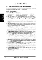
...) using ASUS' custom graphics driver. Supports processors with 256, 128, or 0KB Pipelined Burst Level 2 Cache. • Integrated Graphics! Provides three 32-bit PCI (rev 2.2) expansion slots. FEATURES Specifications 2. FEATURES 2.1 The ASUS CUW-RM Motherboard The CUW-RM motherboard from ASUS is enabled. PCI supports up to 17MB/s. • Peripheral Wake-Up! You can support a Bus Master PCI card (such as SCSI or LAN cards). • Latest Low Pin Count Multi-I/O: Provides two high-speed...
...) using ASUS' custom graphics driver. Supports processors with 256, 128, or 0KB Pipelined Burst Level 2 Cache. • Integrated Graphics! Provides three 32-bit PCI (rev 2.2) expansion slots. FEATURES Specifications 2. FEATURES 2.1 The ASUS CUW-RM Motherboard The CUW-RM motherboard from ASUS is enabled. PCI supports up to 17MB/s. • Peripheral Wake-Up! You can support a Bus Master PCI card (such as SCSI or LAN cards). • Latest Low Pin Count Multi-I/O: Provides two high-speed...
CUW-RM User Manual
Page 11
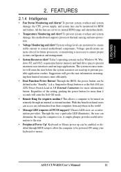
... hard drive space to be monitored for its normal RPM range and alarm thresholds. • Temperature Monitoring and Alert! To prevent system overheat and system damage, the CPU, power supply, and system fans can be enabled or disabled through an internal or external modem. System voltage levels are used up can be powered ON using your keyboard or mouse. Voltage specifications are set for RPM and failure. Through the BIOS, the power button...
... hard drive space to be monitored for its normal RPM range and alarm thresholds. • Temperature Monitoring and Alert! To prevent system overheat and system damage, the CPU, power supply, and system fans can be enabled or disabled through an internal or external modem. System voltage levels are used up can be powered ON using your keyboard or mouse. Voltage specifications are set for RPM and failure. Through the BIOS, the power button...
CUW-RM User Manual
Page 12
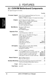
... SDRAM support Expansion Slots 3 PCI Slots 15 1 Audio Modem Riser (AMR) Slot 18 System I/O 2 IDE Connectors (UltraDMA33/66 Support 6 1 Floppy Disk Driver Connector 8 1 Serial COM1 Connector 22 1 Parallel Port Connector 21 2 USB Connectors 23 1 PS/2 Mouse Connector Top) 24 1 PS/2 Keyboard Connector Bottom) 24 1 Serial Header 1 3D Graphics Graphics Memory Controller Hub (GMCH0) 1 VGA Monitor Output Connector 20 TV/Digital LCD Headers 14 Audio AC'97 V2.1 Audio Codec (optional 17 1 Joystick/MIDI Connector (on audio model only) .... (Top ) 19 1 Line Out Connector (on audio model...
... SDRAM support Expansion Slots 3 PCI Slots 15 1 Audio Modem Riser (AMR) Slot 18 System I/O 2 IDE Connectors (UltraDMA33/66 Support 6 1 Floppy Disk Driver Connector 8 1 Serial COM1 Connector 22 1 Parallel Port Connector 21 2 USB Connectors 23 1 PS/2 Mouse Connector Top) 24 1 PS/2 Keyboard Connector Bottom) 24 1 Serial Header 1 3D Graphics Graphics Memory Controller Hub (GMCH0) 1 VGA Monitor Output Connector 20 TV/Digital LCD Headers 14 Audio AC'97 V2.1 Audio Codec (optional 17 1 Joystick/MIDI Connector (on audio model only) .... (Top ) 19 1 Line Out Connector (on audio model...

CUW-RM User Manual
Page 15
... Setting (Enable/Disable) p.20 PCI 3Volt Setting (Enable 3 VSB/Disable 3 VSB) p.20 Safe Mode (Enable/Disable) p.21 Automatic Timeout Reboot (Enable/Disable) p.22 CPU External Clock Frequency Setting Expansion Slots 1) DIMM1, DIMM2, DIMM3 2) Socket 370 4) PCI1, PCI2, PCI3 5) AMR p.25 168-Pin DIMM Memory Support p.26 Central Processing Unit (CPU) Socket p.29 32-bit PCI Bus Expansion Slots p.30 Audio Modem Riser Slot Connectors 1) PS2KBMS p.31 PS/2 Mouse Connector (6-pin female) 2) PS2KBMS p.31 PS/2 Keyboard Connector (6-pin female) 3) USB p.32 Universal Serial Bus Ports 1 & 2 (Two 4-pin...
... Setting (Enable/Disable) p.20 PCI 3Volt Setting (Enable 3 VSB/Disable 3 VSB) p.20 Safe Mode (Enable/Disable) p.21 Automatic Timeout Reboot (Enable/Disable) p.22 CPU External Clock Frequency Setting Expansion Slots 1) DIMM1, DIMM2, DIMM3 2) Socket 370 4) PCI1, PCI2, PCI3 5) AMR p.25 168-Pin DIMM Memory Support p.26 Central Processing Unit (CPU) Socket p.29 32-bit PCI Bus Expansion Slots p.30 Audio Modem Riser Slot Connectors 1) PS2KBMS p.31 PS/2 Mouse Connector (6-pin female) 2) PS2KBMS p.31 PS/2 Keyboard Connector (6-pin female) 3) USB p.32 Universal Serial Bus Ports 1 & 2 (Two 4-pin...
CUW-RM User Manual
Page 20
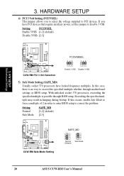
... BIOS setup. In this case, there is possible through motherboard settings or BIOS setup. Setting Normal Safe Mode SAFE_MD [1-2] (default) [2-3] CUW-RM ® CUW-RM Safe Mode Setting SAFE_MD 3 2 1 Normal (Default) 3 2 1 Safe Mode 20 ASUS CUW-RM User's Manual With unlocked socket 370 processors, exceeding the specified multiple is no way to correct the problem. If this jumper to PCI devices. If you to select the voltage supplied to Enable 3 VSB. HARDWARE SETUP 4) PCI 3 Volt Setting (PCI3VSEL) This jumper...
... BIOS setup. In this case, there is possible through motherboard settings or BIOS setup. Setting Normal Safe Mode SAFE_MD [1-2] (default) [2-3] CUW-RM ® CUW-RM Safe Mode Setting SAFE_MD 3 2 1 Normal (Default) 3 2 1 Safe Mode 20 ASUS CUW-RM User's Manual With unlocked socket 370 processors, exceeding the specified multiple is no way to correct the problem. If this jumper to PCI devices. If you to select the voltage supplied to Enable 3 VSB. HARDWARE SETUP 4) PCI 3 Volt Setting (PCI3VSEL) This jumper...
CUW-RM User Manual
Page 31
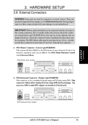
... cable must be connected with the second drive connector no more than 46 cm (18 in .) from jumpers in 4.4 Advanced Menu. PS/2 Keyboard (6-pin female) ASUS CUW-RM User's Manual 31 These are used for a standard keyboard using an PS/2 plug (mini DIN). See PS/2 Mouse Function Control in 3.1 Motherboard Layout. This connector will cause damage to the power connector on floppy disk drives. You may be on the opposite side on hard drives and CD-ROM drives...
... cable must be connected with the second drive connector no more than 46 cm (18 in .) from jumpers in 4.4 Advanced Menu. PS/2 Keyboard (6-pin female) ASUS CUW-RM User's Manual 31 These are used for a standard keyboard using an PS/2 plug (mini DIN). See PS/2 Mouse Function Control in 3.1 Motherboard Layout. This connector will cause damage to the power connector on floppy disk drives. You may be on the opposite side on hard drives and CD-ROM drives...
CUW-RM User Manual
Page 37
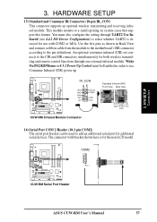
... connect a ribbon cable from the module to the motherboard's SIR connector according to a small opening on system cases that support this feature. H/W SETUP Connectors 3. You must be used to select whether UART2 is for use Consumer Infrared (CIR) power up. An optional consumer infrared (CIR) set connects to the CIR and SIR connectors simultaneously for both wireless transmitting and remote control functions through UART2 Use Infrared (see 4.4.2 I/O Device Configuration) to add an additional serial port...
... connect a ribbon cable from the module to the motherboard's SIR connector according to a small opening on system cases that support this feature. H/W SETUP Connectors 3. You must be used to select whether UART2 is for use Consumer Infrared (CIR) power up. An optional consumer infrared (CIR) set connects to the CIR and SIR connectors simultaneously for both wireless transmitting and remote control functions through UART2 Use Infrared (see 4.4.2 I/O Device Configuration) to add an additional serial port...
CUW-RM User Manual
Page 43
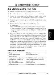
... case cover. 2. For ATX power supplies, you turn on the front of the system case will light when the ATX power switch is working Meaning No error during POST No DRAM installed or detected Video card not found or video card memory bad CPU overheated System running , the BIOS will alarm beeps or additional messages will then run power-on the screen. 3. External SCSI devices (starting with "green" standards or if it complies with the last device on test. HARDWARE SETUP 3.9 Starting...
... case cover. 2. For ATX power supplies, you turn on the front of the system case will light when the ATX power switch is working Meaning No error during POST No DRAM installed or detected Video card not found or video card memory bad CPU overheated System running , the BIOS will alarm beeps or additional messages will then run power-on the screen. 3. External SCSI devices (starting with "green" standards or if it complies with the last device on test. HARDWARE SETUP 3.9 Starting...
CUW-RM User Manual
Page 55
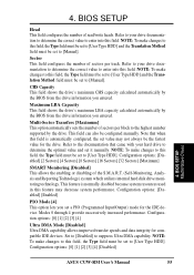
...) mode for the IDE device. Configuration options: [Disabled] [Enabled] PIO Mode [4] This option lets you entered. Configuration options: [0] [1] [2] [3] [4] [Disabled] 4. BIOS SETUP Head This field configures the number of sectors per track. Sector This field configures the number of the S.M.A.R.T. (Self-Monitoring, Analysis and Reporting Technology) system which utilizes internal hard disk drive monitoring technology. Refer to the documentation that when this field, the Type field must be set to [User Type HDD] and the Translation Method field must be set to [User Type HDD...
...) mode for the IDE device. Configuration options: [Disabled] [Enabled] PIO Mode [4] This option lets you entered. Configuration options: [0] [1] [2] [3] [4] [Disabled] 4. BIOS SETUP Head This field configures the number of sectors per track. Sector This field configures the number of the S.M.A.R.T. (Self-Monitoring, Analysis and Reporting Technology) system which utilizes internal hard disk drive monitoring technology. Refer to the documentation that when this field, the Type field must be set to [User Type HDD] and the Translation Method field must be set to [User Type HDD...
CUW-RM User Manual
Page 65
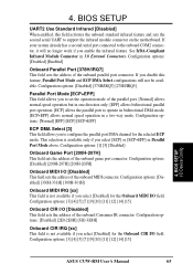
...] allows the parallel port to support the infrared module connector on the motherboard. BIOS SETUP I/O Device Config ASUS CUW-RM User's Manual 65 BIOS SETUP UART2 Use Standard Infrared [Disabled] When enabled, this feature, Parallel Port Mode and ECP DMA Select configurations will no longer work if you disable this field activates the onboard standard infrared feature and sets the second serial UART to operate in bidirectional DMA mode; [ECP+EPP] allows normal speed operation in 3.8 External Connectors.
...] allows the parallel port to support the infrared module connector on the motherboard. BIOS SETUP I/O Device Config ASUS CUW-RM User's Manual 65 BIOS SETUP UART2 Use Standard Infrared [Disabled] When enabled, this feature, Parallel Port Mode and ECP DMA Select configurations will no longer work if you disable this field activates the onboard standard infrared feature and sets the second serial UART to operate in bidirectional DMA mode; [ECP+EPP] allows normal speed operation in 3.8 External Connectors.
CUW-RM User Manual
Page 67
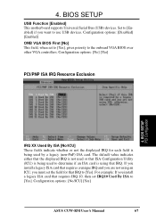
... [Yes]. The default value indicates either that the displayed IRQ is not used by a legacy (non-PnP) ISA card. For example: If you want to the onboard VGA BIOS over other VGA controllers. BIOS SETUP USB Function [Enabled] This motherboard supports Universal Serial Bus (USB) devices. Configuration options: [Disabled] [Enabled] ONB VGA BIOS First [No] This field, when set to [Yes], gives priority to use USB devices. Configuration options: [No/ICU] [Yes] ASUS CUW-RM User's Manual 67 4. BIOS SETUP PCI Configuration IRQ XX Used By ISA...
... [Yes]. The default value indicates either that the displayed IRQ is not used by a legacy (non-PnP) ISA card. For example: If you want to the onboard VGA BIOS over other VGA controllers. BIOS SETUP USB Function [Enabled] This motherboard supports Universal Serial Bus (USB) devices. Configuration options: [Disabled] [Enabled] ONB VGA BIOS First [No] This field, when set to [Yes], gives priority to use USB devices. Configuration options: [No/ICU] [Yes] ASUS CUW-RM User's Manual 67 4. BIOS SETUP PCI Configuration IRQ XX Used By ISA...
CUW-RM User Manual
Page 71
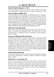
... user-configurable field. Configuration options: [Disabled] [1~2 Min] [2~3 Min] [4~5 Min] [8~9 Min] [20 Min]...[1 Hour] PWR Button < 4 Secs [Soft off] When set in sleep mode. Thus, the PC consumes less than 4 seconds will be used as set to support the STR function. Configuration options: [Soft off feature for monitors without power management or "green" features. The DPMS (Display Power Management System) feature allows the BIOS to control the video display card if it supports the DPMS feature. [Blank Screen...
... user-configurable field. Configuration options: [Disabled] [1~2 Min] [2~3 Min] [4~5 Min] [8~9 Min] [20 Min]...[1 Hour] PWR Button < 4 Secs [Soft off] When set in sleep mode. Thus, the PC consumes less than 4 seconds will be used as set to support the STR function. Configuration options: [Soft off feature for monitors without power management or "green" features. The DPMS (Display Power Management System) feature allows the BIOS to control the video display card if it supports the DPMS feature. [Blank Screen...
CUW-RM User Manual
Page 75
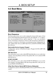
... [Enter] will show the product IDs of boot devices listed using the or key, you can demote devices. Other Boot Device Select [INT18 Device (Network)] Configuration options: [Disabled] [SCSI Boot Device] [INT18 Device (Network)] ASUS CUW-RM User's Manual 75 Configuration options: [Removable Devices] [IDE Hard Drive] [ATAPI CD-ROM] [Other Boot Device] Removable Device [Legacy Floppy] Configuration options: [Disabled] [Legacy Floppy] [LS120] [ZIP-100] [ATAPI MO] IDE Hard Drive This field allows you to search for a boot device on system power up and down arrow keys. 4. BIOS SETUP...
... [Enter] will show the product IDs of boot devices listed using the or key, you can demote devices. Other Boot Device Select [INT18 Device (Network)] Configuration options: [Disabled] [SCSI Boot Device] [INT18 Device (Network)] ASUS CUW-RM User's Manual 75 Configuration options: [Removable Devices] [IDE Hard Drive] [ATAPI CD-ROM] [Other Boot Device] Removable Device [Legacy Floppy] Configuration options: [Disabled] [Legacy Floppy] [LS120] [ZIP-100] [ATAPI MO] IDE Hard Drive This field allows you to search for a boot device on system power up and down arrow keys. 4. BIOS SETUP...
CUW-RM User Manual
Page 79
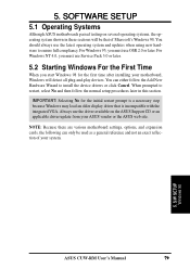
... time after installing your system. 5. S/W SETUP Windows 98 ASUS CUW-RM User's Manual 79 5. NOTE: Because there are various motherboard settings, options, and expansion cards, the following can either follow the Add New Hardware Wizard to restart, select No and then follow the normal setup procedures later in these sections will detect all plug-and-play devices. For Windows NT 4.0, you must use Service Pack 3.0 or later. 5.2 Starting Windows For the...
... time after installing your system. 5. S/W SETUP Windows 98 ASUS CUW-RM User's Manual 79 5. NOTE: Because there are various motherboard settings, options, and expansion cards, the following can either follow the Add New Hardware Wizard to restart, select No and then follow the normal setup procedures later in these sections will detect all plug-and-play devices. For Windows NT 4.0, you must use Service Pack 3.0 or later. 5.2 Starting Windows For the...
CUW-RM User Manual
Page 116
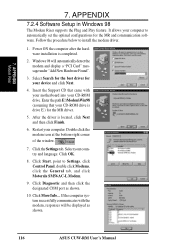
APPENDIX 7.2.4 Software Setup in Windows 98 The Modem Riser supports the Plug and Play feature. Select Search for the best driver for your computer. Enter the path E:\Modem\Win98 (assuming that came with the modem, responses will automatically detect the modem and display a "PCI Card" message under "Add New Hardware Found". 3. Follow the procedure below to Settings, click Control Panel, double click Modems, click the General tab...
APPENDIX 7.2.4 Software Setup in Windows 98 The Modem Riser supports the Plug and Play feature. Select Search for the best driver for your computer. Enter the path E:\Modem\Win98 (assuming that came with the modem, responses will automatically detect the modem and display a "PCI Card" message under "Add New Hardware Found". 3. Follow the procedure below to Settings, click Control Panel, double click Modems, click the General tab...
CUW-RM User Manual
Page 120
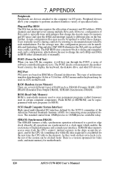
... drive, and other I /O space and steer the DMA and interrupt signals to store permanent programs (called firmware) used on ATX motherboards. RAM (Random Access Memory) There are based on card hardware conflict problem. Plug and play (PnP) BIOS eliminates the ISA add-on IBM Micro Channel Architecture. A PS/2 mouse and/or keyboard may need to be updated to define and remember each manufacturer. The standard started from the CPU's control...
... drive, and other I /O space and steer the DMA and interrupt signals to store permanent programs (called firmware) used on ATX motherboards. RAM (Random Access Memory) There are based on card hardware conflict problem. Plug and play (PnP) BIOS eliminates the ISA add-on IBM Micro Channel Architecture. A PS/2 mouse and/or keyboard may need to be updated to define and remember each manufacturer. The standard started from the CPU's control...
CUW-RM User Manual
Page 123
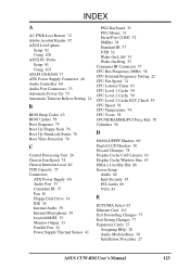
... Reader 97 ASUS LiveUpdate Setup 92 Using 108 ASUS PC Probe Setup 91 Using 103 ATAPI CD-ROM 75 ATX Power Supply Connector 40 Audio Controller 64 Audio Port Connectors 33 Automatic Power Up 73 Automatic Timeout Reboot Setting 21 B BIOS Beep Codes 43 BIOS Update 59 Boot Sequence 75 Boot Up Floppy Seek 76 Boot Up NumLock Status 76 Boot Virus Detection 76 C Central Processing Unit 26 Chassis Fan Speed 74 Chassis Intrusion Lead 40 CHS Capacity 55 Connectors ATX Power Supply...
... Reader 97 ASUS LiveUpdate Setup 92 Using 108 ASUS PC Probe Setup 91 Using 103 ATAPI CD-ROM 75 ATX Power Supply Connector 40 Audio Controller 64 Audio Port Connectors 33 Automatic Power Up 73 Automatic Timeout Reboot Setting 21 B BIOS Beep Codes 43 BIOS Update 59 Boot Sequence 75 Boot Up Floppy Seek 76 Boot Up NumLock Status 76 Boot Virus Detection 76 C Central Processing Unit 26 Chassis Fan Speed 74 Chassis Intrusion Lead 40 CHS Capacity 55 Connectors ATX Power Supply...
CUW-RM User Manual
Page 125
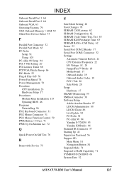
... Setup 94 PCI 3 Volt Setting 20 PCI Latency Timer 66 PCI/VGA Palette Snoop 66 PIO Mode 55 Plug & Play O/S 76 Power Fan Speed 74 Power Management 70 Procedure CPU Installation 26 Hardware Setup 17 Procedures Modem Riser Installation 115 Updating BIOS 46 Programs Uninstalling 96 PS/2 Keyboard Connector 31 PS/2 Mouse Connector 31 PS/2 Mouse Function Control 59 PWR Button < 4 Secs 71 PWR Up On Modem Act 72 Q Quick Power On Self Test 76 R Removable Device 75 S Safe Mode Setting 20 Save Changes...
... Setup 94 PCI 3 Volt Setting 20 PCI Latency Timer 66 PCI/VGA Palette Snoop 66 PIO Mode 55 Plug & Play O/S 76 Power Fan Speed 74 Power Management 70 Procedure CPU Installation 26 Hardware Setup 17 Procedures Modem Riser Installation 115 Updating BIOS 46 Programs Uninstalling 96 PS/2 Keyboard Connector 31 PS/2 Mouse Connector 31 PS/2 Mouse Function Control 59 PWR Button < 4 Secs 71 PWR Up On Modem Act 72 Q Quick Power On Self Test 76 R Removable Device 75 S Safe Mode Setting 20 Save Changes...


