User Guide
Page 6
... Supports Jack-Detection and Front Panel Jack-Retasking (continued on the CPU types. ** Refer to www.asus.com for Intel® CPU support list. B150M-A specifications summary CPU Chipset Memory Graphics Expansion slots Storage Audio LGA1151 socket for Intel® 6th Generation Core...maximum resolution of 1920 x 1200 @60Hz Supports up your retailer. Package contents Check your motherboard package for the following items. Motherboard ASUS B150M-A motherboard Cables 2 x Serial ATA 6.0 Gb/s cables Accessories Application DVD 1 x I/O Shield Support DVD Documentation User Guide If any...
... Supports Jack-Detection and Front Panel Jack-Retasking (continued on the CPU types. ** Refer to www.asus.com for Intel® CPU support list. B150M-A specifications summary CPU Chipset Memory Graphics Expansion slots Storage Audio LGA1151 socket for Intel® 6th Generation Core...maximum resolution of 1920 x 1200 @60Hz Supports up your retailer. Package contents Check your motherboard package for the following items. Motherboard ASUS B150M-A motherboard Cables 2 x Serial ATA 6.0 Gb/s cables Accessories Application DVD 1 x I/O Shield Support DVD Documentation User Guide If any...
User Guide
Page 11
... of the chassis as the power supply case, to avoid damaging them due to static electricity. • Hold components by the edges to the chassis. ASUS B150M-A 1-1 Failure to ensure that the ATX power supply is switched off or the power cord is detached from the wall socket before installing or removing...
... of the chassis as the power supply case, to avoid damaging them due to static electricity. • Hold components by the edges to the chassis. ASUS B150M-A 1-1 Failure to ensure that the ATX power supply is switched off or the power cord is detached from the wall socket before installing or removing...
User Guide
Page 13
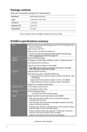
... connector (4-1 pin CHASSIS) 9. Serial port connector (10-1 pin COM) 16. Intel® LGA1151 CPU socket 4. DDR4 DIMM slots 5. LPT connector (26-1 pin LPT) 14. B150M-A B150M-A CPU socket LGA1151 ASUS B150M-A 1-3 Intel® Serial ATA 6.0 Gb/s connector (7-pin SATA6G_1~6) 6. Front panel audio connector (10-1 pin AAFP) Page 1-17 1-15 1-3 1-7 1-20 1-19 1-20 1-12 1-11...
... connector (4-1 pin CHASSIS) 9. Serial port connector (10-1 pin COM) 16. Intel® LGA1151 CPU socket 4. DDR4 DIMM slots 5. LPT connector (26-1 pin LPT) 14. B150M-A B150M-A CPU socket LGA1151 ASUS B150M-A 1-3 Intel® Serial ATA 6.0 Gb/s connector (7-pin SATA6G_1~6) 6. Front panel audio connector (10-1 pin AAFP) Page 1-17 1-15 1-3 1-7 1-20 1-19 1-20 1-12 1-11...

User Guide
Page 15
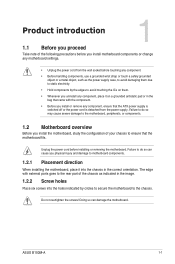
4 C 5 A B 1.3.2 CPU heatsink and fan assembly installation Apply the Thermal Interface Material to the CPU heatsink and CPU before you install the heatsink and fan if necessary. ASUS B150M-A 1-5
4 C 5 A B 1.3.2 CPU heatsink and fan assembly installation Apply the Thermal Interface Material to the CPU heatsink and CPU before you install the heatsink and fan if necessary. ASUS B150M-A 1-5

User Guide
Page 17
...memory 1.4.1 Overview This motherboard comes with four Double Data Rate 4 (DDR4) Dual Inline Memory Module (DIMM) sockets. Recommended memory configurations ASUS B150M-A 1-7 A DDR4 module is recommended to Intel® CPU spec, DIMM voltage below . You can refer to the DDR4 slot. DO ... recommended memory population below 1.35 V is notched differently from a DDR, DDR2, or DDR3 module. DIMM_A1 DIMM_A2 DIMM_B1 DIMM_B2 Channel B150M-A Channel A Channel B B150M-A 288-pin DDR4 DIMM sockets Sockets DIMM_A1 & DIMM_A2 DIMM_B1 & DIMM_B2 1.4.2 Memory configurations You may install 2 GB, 4 GB,...
...memory 1.4.1 Overview This motherboard comes with four Double Data Rate 4 (DDR4) Dual Inline Memory Module (DIMM) sockets. Recommended memory configurations ASUS B150M-A 1-7 A DDR4 module is recommended to Intel® CPU spec, DIMM voltage below . You can refer to the DDR4 slot. DO ... recommended memory population below 1.35 V is notched differently from a DDR, DDR2, or DDR3 module. DIMM_A1 DIMM_A2 DIMM_B1 DIMM_B2 Channel B150M-A Channel A Channel B B150M-A 288-pin DDR4 DIMM sockets Sockets DIMM_A1 & DIMM_A2 DIMM_B1 & DIMM_B2 1.4.2 Memory configurations You may install 2 GB, 4 GB,...

User Guide
Page 19
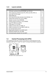
1.4.3 1 Installing a DIMM 2 3 To remove a DIMM B A ASUS B150M-A 1-9
1.4.3 1 Installing a DIMM 2 3 To remove a DIMM B A ASUS B150M-A 1-9
User Guide
Page 21
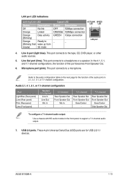
... GND PIN 1 B150M-A Clear RTC RAM To erase the RTC RAM: 1. You can clear the CMOS memory of date, time, and system setup parameters by erasing the CMOS ... RAM data. shared - - - - --- 1.6 Headers 1. Turn OFF the computer and unplug the power cord. 2. Plug the power cord and turn ON the computer. 4. shared - - - - - - shared - - - - --- shared - - - - --- ASUS B150M-A 1-11 After clearing the CMOS, reinstall the battery. • You do not help, remove the onboard battery and short the two pins again to overclocking...
... GND PIN 1 B150M-A Clear RTC RAM To erase the RTC RAM: 1. You can clear the CMOS memory of date, time, and system setup parameters by erasing the CMOS ... RAM data. shared - - - - --- 1.6 Headers 1. Turn OFF the computer and unplug the power cord. 2. Plug the power cord and turn ON the computer. 4. shared - - - - - - shared - - - - --- shared - - - - --- ASUS B150M-A 1-11 After clearing the CMOS, reinstall the battery. • You do not help, remove the onboard battery and short the two pins again to overclocking...
User Guide
Page 23
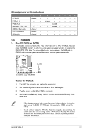
... up from steady) S5 mode Speed LED Status Description OFF 10Mbps connection ORANGE 100Mbps connection GREEN 1Gbps connection _ _ ACT/LINK SPEED LED LED LAN port 4. ASUS B150M-A 1-13 These 4-pin Universal Serial Bus (USB) ports are for the function of this port becomes Front Speaker Out. 6. Microphone port (pink). LAN port LED...
... up from steady) S5 mode Speed LED Status Description OFF 10Mbps connection ORANGE 100Mbps connection GREEN 1Gbps connection _ _ ACT/LINK SPEED LED LED LAN port 4. ASUS B150M-A 1-13 These 4-pin Universal Serial Bus (USB) ports are for the function of this port becomes Front Speaker Out. 6. Microphone port (pink). LAN port LED...
User Guide
Page 25
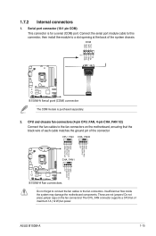
... port (COM) connector The COM module is for a serial (COM) port. Insufficient air flow inside the system may damage the motherboard components. ASUS B150M-A 1-15 The CPU_FAN connector supports a CPU fan of the system chassis. Connect the serial port module cable to this connector, then install the module to ... connector CPU_FAN CHA_FAN2 CPU FAN PWM CPU FAN IN CPU FAN PWR GND +5V CHA FAN IN CHA FAN PWR GND B150M-A CHA_FAN1 +5V CHA FAN IN CHA FAN PWR GND B150M-A Fan connectors Do not forget to connect the fan cables to a slot opening at the back of maximum 1A (12...
... port (COM) connector The COM module is for a serial (COM) port. Insufficient air flow inside the system may damage the motherboard components. ASUS B150M-A 1-15 The CPU_FAN connector supports a CPU fan of the system chassis. Connect the serial port module cable to this connector, then install the module to ... connector CPU_FAN CHA_FAN2 CPU FAN PWM CPU FAN IN CPU FAN PWR GND +5V CHA FAN IN CHA FAN PWR GND B150M-A CHA_FAN1 +5V CHA FAN IN CHA FAN PWR GND B150M-A Fan connectors Do not forget to connect the fan cables to a slot opening at the back of maximum 1A (12...

User Guide
Page 27
...the system will not boot up if the power is inadequate. • If you intend to the Recommended Power Supply Wattage Calculator at http://support.asus. 5. The power supply plugs are for details. com/PowerSupplyCalculator/PSCalculator.aspx?SLanguage=en-us for ATX power supply plugs. A B ATX12V EATXPWR ...(or later version) and provides a minimum power of 350 W. • DO NOT forget to fit these connectors in only one orientation. ASUS B150M-A 1-17 ATX power connectors (24-pin EATXPWR, 4-pin EATX12V) These connectors are designed to connect the 4-pin ATX +12V power plug.
...the system will not boot up if the power is inadequate. • If you intend to the Recommended Power Supply Wattage Calculator at http://support.asus. 5. The power supply plugs are for details. com/PowerSupplyCalculator/PSCalculator.aspx?SLanguage=en-us for ATX power supply plugs. A B ATX12V EATXPWR ...(or later version) and provides a minimum power of 350 W. • DO NOT forget to fit these connectors in only one orientation. ASUS B150M-A 1-17 ATX power connectors (24-pin EATXPWR, 4-pin EATX12V) These connectors are designed to connect the 4-pin ATX +12V power plug.

User Guide
Page 29
... panel connector • System power LED (2-pin PWRLED) This 2-pin connector is for the HDD Activity LED. ASUS B150M-A 1-19 F_PANEL +PWR LED PWR BTN PWR_LED+ PWR_LEDPWR GND HDD_LED+ HDD_LED- The system power LED lights up or flashes when data is read from or ...
... panel connector • System power LED (2-pin PWRLED) This 2-pin connector is for the HDD Activity LED. ASUS B150M-A 1-19 F_PANEL +PWR LED PWR BTN PWR_LED+ PWR_LEDPWR GND HDD_LED+ HDD_LED- The system power LED lights up or flashes when data is read from or ...

User Guide
Page 31
...#_R O_LPT_XPD0_R O_LPT_XPD1_R O_LPT_XPD2_R O_LPT_XPD3_R O_LPT_XPD4_R O_LPT_XPD5_R O_LPT_XPD6_R O_LPT_XPD7_R O_LPT_ACK#_R O_LPT_BUSY_R O_LPT_PE_R O_LPT_SLCT_R B150M-A LPT PIN 1 B150M-A Parallel Port connector ASUS B150M-A 1-21 TPM F_CLKRUN F_SERIRQ F_FRAME# F_LAD3 F_LAD2 F_LAD1 F_LAD0 B150M-A PIN 1 +3VSB S_PCIRST#_TBD GND C_PCICLK_TPM +3V +3V B150M-A TPM connector The TPM module is the parallel port interface on IBM PC-compatible...
...#_R O_LPT_XPD0_R O_LPT_XPD1_R O_LPT_XPD2_R O_LPT_XPD3_R O_LPT_XPD4_R O_LPT_XPD5_R O_LPT_XPD6_R O_LPT_XPD7_R O_LPT_ACK#_R O_LPT_BUSY_R O_LPT_PE_R O_LPT_SLCT_R B150M-A LPT PIN 1 B150M-A Parallel Port connector ASUS B150M-A 1-21 TPM F_CLKRUN F_SERIRQ F_FRAME# F_LAD3 F_LAD2 F_LAD1 F_LAD0 B150M-A PIN 1 +3VSB S_PCIRST#_TBD GND C_PCICLK_TPM +3V +3V B150M-A TPM connector The TPM module is the parallel port interface on IBM PC-compatible...
User Guide
Page 33
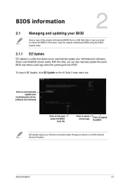
... logo Click to automatically update your BIOS Save a copy of the original motherboard BIOS file to a USB flash disk in the future. ASUS B150M-A 2-1 Copy the original motherboard BIOS using the ASUS Update utility. 2.1.1 EZ Update EZ Update is a utility that allows you to update the BIOS EZ Update requires an Internet connection...
... logo Click to automatically update your BIOS Save a copy of the original motherboard BIOS file to a USB flash disk in the future. ASUS B150M-A 2-1 Copy the original motherboard BIOS using the ASUS Update utility. 2.1.1 EZ Update EZ Update is a utility that allows you to update the BIOS EZ Update requires an Internet connection...
User Guide
Page 35
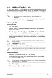
... updating BIOS • Prepare the motherboard support DVD and a USB flash drive. • Download the latest BIOS file and BIOS Updater from the ASUS website at www.asus.com. ASUS B150M-A 2-3 To ensure system compatibility and stability, we recommend that contains the updated BIOS file. • Before using this section are for the BIOS...
... updating BIOS • Prepare the motherboard support DVD and a USB flash drive. • Download the latest BIOS file and BIOS Updater from the ASUS website at www.asus.com. ASUS B150M-A 2-3 To ensure system compatibility and stability, we recommend that contains the updated BIOS file. • Before using this section are for the BIOS...

User Guide
Page 37
... the Load Optimized Defaults item under the Exit BIOS menu. See section 2.10 Exit Menu for DOS V1.30 [2014/01/01] Current ROM BOARD: B150M-A VER: 0308 (H :00 B :00) DATE: 08/14/2015 PATH: C:\ Update ROM BOARD: Unknown VER: Unknown DATE: Unknown C: FORMAN~1 D: B15A4.CAP 16779264 2015-08... [Up/Down/Home/End] Move [Tab] Switch [Esc] Exit [V] Drive Info Files panel 3. Are you sure you want to confirm the BIOS update. ASUS B150M-A 2-5 After the BIOS Updater checks the selected BIOS file, select Yes to update the BIOS? When BIOS update is not supported due to exit BIOS...
... the Load Optimized Defaults item under the Exit BIOS menu. See section 2.10 Exit Menu for DOS V1.30 [2014/01/01] Current ROM BOARD: B150M-A VER: 0308 (H :00 B :00) DATE: 08/14/2015 PATH: C:\ Update ROM BOARD: Unknown VER: Unknown DATE: Unknown C: FORMAN~1 D: B15A4.CAP 16779264 2015-08... [Up/Down/Home/End] Move [Tab] Switch [Esc] Exit [V] Drive Info Files panel 3. Are you sure you want to confirm the BIOS update. ASUS B150M-A 2-5 After the BIOS Updater checks the selected BIOS file, select Yes to update the BIOS? When BIOS update is not supported due to exit BIOS...
User Guide
Page 39
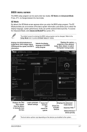
... display language of the BIOS setup program Displays the system properties of the basic system information, and allows you an overview of the selected mode. ASUS B150M-A 2-7 Click to change between the two modes. Click the button to select the display language, system performance mode, fan profile and boot device priority. The...
... display language of the BIOS setup program Displays the system properties of the basic system information, and allows you an overview of the selected mode. ASUS B150M-A 2-7 Click to change between the two modes. Click the button to select the display language, system performance mode, fan profile and boot device priority. The...
User Guide
Page 41
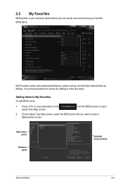
... boot related items by adding or removing items. Adding items to My Favorites To add BIOS items: 1. Main menu panel Submenu panel Selected shortcut items ASUS B150M-A 2-9 2.3 My Favorites MyFavorites is your personal space where you want to save and access your keyboard or click Setup Tree Map screen. On the Setup...
... boot related items by adding or removing items. Adding items to My Favorites To add BIOS items: 1. Main menu panel Submenu panel Selected shortcut items ASUS B150M-A 2-9 2.3 My Favorites MyFavorites is your personal space where you want to save and access your keyboard or click Setup Tree Map screen. On the Setup...
User Guide
Page 43
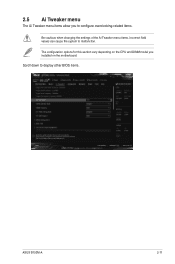
2.5 Ai Tweaker menu The Ai Tweaker menu items allow you installed on the CPU and DIMM model you to configure overclocking-related items. Be cautious when changing the settings of the Ai Tweaker menu items. Incorrect field values can cause the system to display other BIOS items. ASUS B150M-A 2-11 Scroll down to malfunction. The configuration options for this section vary depending on the motherboard.
2.5 Ai Tweaker menu The Ai Tweaker menu items allow you installed on the CPU and DIMM model you to configure overclocking-related items. Be cautious when changing the settings of the Ai Tweaker menu items. Incorrect field values can cause the system to display other BIOS items. ASUS B150M-A 2-11 Scroll down to malfunction. The configuration options for this section vary depending on the motherboard.

User Guide
Page 45
2.8 Boot menu The Boot menu items allow you to configure options for the BIOS items, and save or discard your changes to the BIOS items. ASUS B150M-A 2-13 Select an item then press to display the submenu. 2.10 Exit menu The Exit menu items allow you to load the optimal default values for special functions. Scroll down to display the other BIOS items. 2.9 Tool menu The Tool menu items allow you to change the system boot options.
2.8 Boot menu The Boot menu items allow you to configure options for the BIOS items, and save or discard your changes to the BIOS items. ASUS B150M-A 2-13 Select an item then press to display the submenu. 2.10 Exit menu The Exit menu items allow you to load the optimal default values for special functions. Scroll down to display the other BIOS items. 2.9 Tool menu The Tool menu items allow you to change the system boot options.

User Guide
Page 47
... Part 15 of the Canadian interference-causing equipment regulations. Appendices Notices Federal Communications Commission Statement This device complies with Industry Canada license exempt RSS standard(s). ASUS B150M-A A-1
... Part 15 of the Canadian interference-causing equipment regulations. Appendices Notices Federal Communications Commission Statement This device complies with Industry Canada license exempt RSS standard(s). ASUS B150M-A A-1


