Asus B150M-V PLUS Support and Manuals
Get Help and Manuals for this Asus item
View All Support Options Below
Free Asus B150M-V PLUS manuals!
Problems with Asus B150M-V PLUS?
Ask a Question
Free Asus B150M-V PLUS manuals!
Problems with Asus B150M-V PLUS?
Ask a Question
Popular Asus B150M-V PLUS Manual Pages
Motherboard Pin Definition.English - Page 3
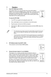
...system, then the BIOS automatically resets parameter settings to clear the Real Time Clock (RTC) RAM in CMOS, which include system setup information such as system passwords.
+3V_BAT GND
CLRTC
PIN 1
To... intrusion header (4-1 pin CHASSIS)
+5VSB_MB Chassis Signal GND
This header is removed or replaced. The chassis intrusion sensor or switch sends a highlevel signal to overclocking, use the ...
Motherboard Pin Definition.English - Page 4
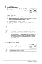
...automatically reset parameter settings to clear ... include system setup information such as system passwords. Move the...setup parameters by erasing the CMOS RTC RAM data. Turn OFF the computer and unplug the power cord.
2.
2
Jumpers
1. Plug the power cord and turn ON the computer.
4. DIS_ME
12
23
Normal (Default)
Disable ME
Disable the Intel® ME function before updating...
Motherboard Pin Definition.English - Page 5

...Display panel backlight power selector (3-pin BLKT_PWR_SEL) BLKT_PWR_SEL
12 23
Pins 1-2 (Default)
2-3
Setting 12V 19V
12V
19V
(Default)
6. otherwise, the system would not power up from...for eDP
Motherboard Pin Definition
1-5 LVDS panel/eDP selector (3-pin FPD_SEL)
Pins 1-2 (Default)
2-3
Setting LVDS eDP
VCC_PWR_SEL
1
3V (Default)
2
5V
3
12V
FPD_SEL
12 23
for LVDS (Default)
...
Motherboard Pin Definition.English - Page 6
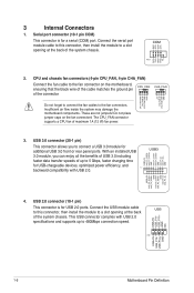
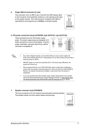
...chargeable devices, optimized power efficiency, and
PIN 1
backward compatibility with USB 2.0
specifications and supports up to the fan connectors.
These are not jumpers! USB3+5V IntA_P1_SSRXIntA_P1_SSRX+ GND...480Mbps connection speed. Connect the USB module cable
USB
to this connector, then install the module to the fan connector on the fan connectors!
USB3
USB3+5V ...
Motherboard Pin Definition.English - Page 7
...) Groud
PIN 1
6. The power supply plugs are designed to a slot opening at http://support.asus. PIN 1
GND GND
ATX12V
+12V DC +12V DC
EATX12V
EATXPWR
+12V DC +12V DC...-consuming devices or when you intend to install additional devices. Otherwise, the system will not boot up.
• We recommend that complies with USB 2.0 specifications and supports up if the power is inadequate.
...
Motherboard Pin Definition.English - Page 8
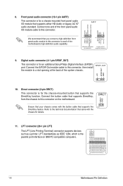
... front panel audio
I /O module that came with the button cable that supports DirectKey, from the chassis to this connector, then install the module to avail of the system chassis.
+5V SPDIFOUT GND
10....#_R GND GND GND GND GND GND GND GND
11. 8.
Connect the button cable that supports the PIN 1 DirectKey feature.
DRCT
DRCT GND
Ensure that your chassis comes with the chassis for...
Motherboard Pin Definition.English - Page 9
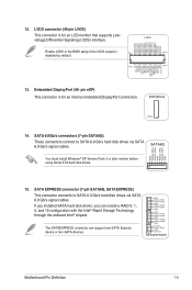
...support one SATA Express device or two SATA devices.
ODD_Lane3_P ODD_Lane3_N ODD_Lane2_P ODD_Lane2_N ODD_Lane1_P ODD_Lane1_N ODD_Lane0_P ODD_Lane0_N EVEN_Lane3_P EVEN_Lane3_N EVEN_Lane2_P EVEN_Lane2_N EVEN_Lane1_P EVEN_Lane1_N EVEN_Lane0_P EVEN_Lane0_N EDID_GND LCD_VCC LCD_VCC LCD_VCC
Enable LVDS in the BIOS setup...default.
SATA6G
You must install Windows® XP Service Pack 3 or later ...
Motherboard Pin Definition.English - Page 10
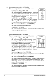
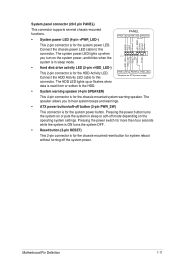
... the HDD Activity LED. System panel connector (10-1 pin F_PANEL)
This connector supports several chassis-mounted functions. • System power LED (2-pin PWR_LED)
F_PANEL
+PWR_LED- System panel connector ...connector is in sleep mode.
The system power
LED lights up when you turn on the BIOS settings. 16.
Connect the chassis power LED cable to the HDD.
+HDD_LED RESET
• ATX...
Motherboard Pin Definition.English - Page 11
...soft-off the system power.
Pressing the power button turns the system on the operating system settings.
The HDD LED lights up when
you to the HDD.
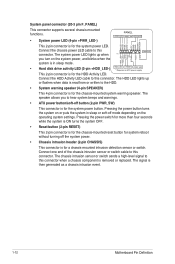
+HDD_LED- Pressing the power ... for the system power LED. System panel connector (20-5 pin PANEL)
This connector supports several chassis-mounted functions.
• System power LED (4-pin +PWR_LED-)
PANEL
+PWR_LED-
Connect the chassis ...
Motherboard Pin Definition.English - Page 12
...for the chassis-mounted system warning speaker. The signal is removed or replaced. GND Reset
NC PLED+ PLED- Pressing the power switch for more ...HDD_LED+ HDD_LED- The speaker allows you turn on the operating system settings. PWR_SW SPEAKER
PLED+ PLEDPWR GND +5V GND GND Speaker Intruder#
...supports several chassis-mounted functions.
• System power LED (4-pin +PWR_LED-)
PANEL
+PWR_LED-...
Motherboard Pin Definition.English - Page 13
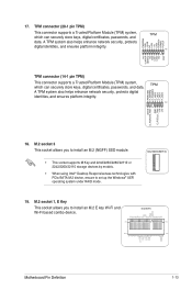
...certificates, passwords, and data. TPM
A TPM system also helps enhance network security, protects digital
identities, and ensures platform integrity. 17. M.2 socket 3 This socket allows you to set up the...This socket allows you to install an M.2 (NGFF) SSD module.
• This socket supports M Key and 2242/2260/2280/22110 or 2242/2260/22110 storage devices by models.
• When using Intel...
Motherboard Pin Definition.English - Page 14
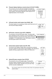
...backlight.
Internal stereo speaker header (4-pin INT_SPK)
The internal mono speaker header allows connection to the specification sheet of 4 Ohms at 3 Watts (rms). PIN 1
24. Find the proper orientation and...capability. INT_SPK
Front_L- ATX19V
GND
PIN 1
DC_JACK_IN
This connector supports 12V and 19V by models. 20. SATA power connector (15-pin SATA_PWRCON)
This connector is capable of driving...
Motherboard Pin Definition.English - Page 16

...a 2-digit error code that the system is designed to locate the root problem within seconds.
...4. It blinks when data is being written into or read from the hard disk drive. Q-Code LED (Q_CODE) The Q-Code LED design provides you with a standby power LED that lights up when the KeyBot button is a reminder that you press the BIOS Flashback button for BIOS update...
Motherboard Pin Definition.English - Page 17
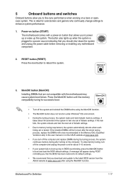
... fails, the system reboots and test the next set of failsafe settings.
button (MemOK!) Installing DIMMs that you download and update to memory tuning requirement, the system automatically reboots when each timing set of failsafe settings.
• Due to the latest BIOS version from the ASUS website at www.asus.com.
• If you should shut down the...
Motherboard Pin Definition.English - Page 18

... this button to clear the BIOS setup information only when the systems hangs due to overclocking.
5.
Slow Mode switch Slow Mode switch allows your system to [Enable] before using the LN2 cooling system.
The KeyBot feature supports USB keyboards only. SOUNDSTAGE
7. KEBOT
6. The debug code on the Q-Code LED shows the current Sonic SoundStage...
Asus B150M-V PLUS Reviews
We have not received any reviews for Asus yet.