User Manual
Page 3
Contents Notices...v Safety information vi About this guide vi AT4NM10-I specifications summary viii Chapter 1: Product introduction 1.1 Before you proceed 1-1 1.2 Motherboard overview 1-2 1.2.1 Motherboard layout 1-2 1.2.2 Layout contents 1-2 1.3 Central ... 1.7.2 Internal connectors 1-12 1.8 Software support 1-18 1.8.1 Installing an operating system 1-18 1.8.2 Support DVD information 1-18 Chapter 2: BIOS information 2.1 Managing and updating your BIOS 2-1 2.1.1 ASUS Update utility 2-1 2.1.2 ASUS EZ Flash 2 2-2 2.1.3 ASUS CrashFree BIOS 2-3 2.2 BIOS setup program 2-4 iii
Contents Notices...v Safety information vi About this guide vi AT4NM10-I specifications summary viii Chapter 1: Product introduction 1.1 Before you proceed 1-1 1.2 Motherboard overview 1-2 1.2.1 Motherboard layout 1-2 1.2.2 Layout contents 1-2 1.3 Central ... 1.7.2 Internal connectors 1-12 1.8 Software support 1-18 1.8.1 Installing an operating system 1-18 1.8.2 Support DVD information 1-18 Chapter 2: BIOS information 2.1 Managing and updating your BIOS 2-1 2.1.1 ASUS Update utility 2-1 2.1.2 ASUS EZ Flash 2 2-2 2.1.3 ASUS CrashFree BIOS 2-3 2.2 BIOS setup program 2-4 iii

User Manual
Page 6
... • Chapter 1: Product introduction This chapter describes the features of the motherboard and the new technology it supports. • Chapter 2: BIOS information This chapter tells how to fix it , carefully read all cables are correctly connected and the power cables are connected. How this ...using the product, ensure that all the manuals that your power supply is broken, do not try to change system settings through the BIOS Setup menus. vi These devices could interrupt the grounding circuit. • Ensure that came with the product, contact a qualified service ...
... • Chapter 1: Product introduction This chapter describes the features of the motherboard and the new technology it supports. • Chapter 2: BIOS information This chapter tells how to fix it , carefully read all cables are correctly connected and the power cables are connected. How this ...using the product, ensure that all the manuals that your power supply is broken, do not try to change system settings through the BIOS Setup menus. vi These devices could interrupt the grounding circuit. • Ensure that came with the product, contact a qualified service ...
User Manual
Page 8
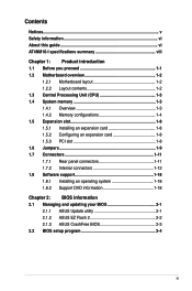
AT4NM10-I specifications summary CPU Chipset Memory Graphics Expansion slot Storage Audio LAN USB ASUS special features Rear panel ports Integrated Intel® Atom™ D410 processor Intel® NM10 Single channel memory architecture - 2 x 240-pin DIMM... 4GB unbuffered non-ECC DDR2 800/667 MHz memory modules * Refer to 8 USB 2.0/1.1 ports (4 ports at mid-board, 4 ports at back panel) ASUS CrashFree BIOS 3 ASUS EZ Flash 2 ASUS MyLogo 2™ ASUS AI NET 2 ASUS Express Gate 1 x PS/2 Keyboard port 1 x PS/2 Mouse port 1 x COM port 1 x VGA port 1 x LPT port 1 x LAN (RJ-45) port 4 x USB...
AT4NM10-I specifications summary CPU Chipset Memory Graphics Expansion slot Storage Audio LAN USB ASUS special features Rear panel ports Integrated Intel® Atom™ D410 processor Intel® NM10 Single channel memory architecture - 2 x 240-pin DIMM... 4GB unbuffered non-ECC DDR2 800/667 MHz memory modules * Refer to 8 USB 2.0/1.1 ports (4 ports at mid-board, 4 ports at back panel) ASUS CrashFree BIOS 3 ASUS EZ Flash 2 ASUS MyLogo 2™ ASUS AI NET 2 ASUS Express Gate 1 x PS/2 Keyboard port 1 x PS/2 Mouse port 1 x COM port 1 x VGA port 1 x LPT port 1 x LAN (RJ-45) port 4 x USB...
User Manual
Page 9
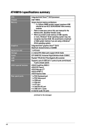
AT4NM10-I specifications summary Internal connectors BIOS features Accessories Support DVD contents Form Factor 2 x USB 2.0/1.1 connector supports additional 4 USB 2.0/1.1 ports 1 x CPU fan connector 1 x Chassis fan connector 1 x Chassis intrusion connector 1 x S/PDIF Out... panel audio connector 1 x 24-pin EATX power connector 1 x 4-pin ATX 12V power connector 8 Mb Flash ROM, AMI BIOS, PnP, DMI2.0, WfM2.0, SMBIOS 2.5 1 x Serial ATA cable 1 x I/O shield 1 x User Manual Drivers ASUS PC Probe II ASUS Update Anti-virus software (OEM version) Mini ITX form factor: 6.75 in x 6.75 in (17.1cm x 17.1cm...
AT4NM10-I specifications summary Internal connectors BIOS features Accessories Support DVD contents Form Factor 2 x USB 2.0/1.1 connector supports additional 4 USB 2.0/1.1 ports 1 x CPU fan connector 1 x Chassis fan connector 1 x Chassis intrusion connector 1 x S/PDIF Out... panel audio connector 1 x 24-pin EATX power connector 1 x 4-pin ATX 12V power connector 8 Mb Flash ROM, AMI BIOS, PnP, DMI2.0, WfM2.0, SMBIOS 2.5 1 x Serial ATA cable 1 x I/O shield 1 x User Manual Drivers ASUS PC Probe II ASUS Update Anti-virus software (OEM version) Mini ITX form factor: 6.75 in x 6.75 in (17.1cm x 17.1cm...
User Manual
Page 17
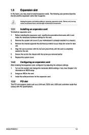
... install an expansion card: 1. Before installing the expansion card, read the documentation that comply with the screw you intend to install expansion cards. ASUS AT4NM10-I 1-8 Failure to do so may need to use . 4. Unplug the power cord before adding or removing expansion cards. Remove the system unit... cover (if your motherboard is completely seated on the system and change the necessary BIOS settings, if any. Align the card connector with it and make the necessary hardware settings for the expansion card. 1.5.3 PCI slot The...
... install an expansion card: 1. Before installing the expansion card, read the documentation that comply with the screw you intend to install expansion cards. ASUS AT4NM10-I 1-8 Failure to do so may need to use . 4. Unplug the power cord before adding or removing expansion cards. Remove the system unit... cover (if your motherboard is completely seated on the system and change the necessary BIOS settings, if any. Align the card connector with it and make the necessary hardware settings for the expansion card. 1.5.3 PCI slot The...
User Manual
Page 18
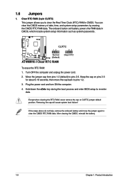
... OFF the computer and unplug the power cord. 2. AT4NM10-I Clear RTC RAM To erase the RTC RAM: 1. Move the jumper cap from pins 1-2 (default) to re-enter data. Except when clearing the RTC RAM, ... system setup information such as system passwords. Removing the cap will cause system boot failure! Hold down the key during the boot process and enter BIOS setup to pins 2-3. The onboard button cell battery powers the RAM data in CMOS. You can clear the CMOS memory of date, time, and system...
... OFF the computer and unplug the power cord. 2. AT4NM10-I Clear RTC RAM To erase the RTC RAM: 1. Move the jumper cap from pins 1-2 (default) to re-enter data. Except when clearing the RTC RAM, ... system setup information such as system passwords. Removing the cap will cause system boot failure! Hold down the key during the boot process and enter BIOS setup to pins 2-3. The onboard button cell battery powers the RAM data in CMOS. You can clear the CMOS memory of date, time, and system...
User Manual
Page 19
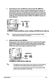
... 1-4 wake-up The total current consumed must NOT exceed the power supply capability (+5VSB) whether under normal condition or in reduced power mode). ASUS AT4NM10-I 12 23 2. otherwise, the system would not power up feature requires a power supply that can supply at least 1A on the keyboard, ...power supply that can wake up from S1 sleep mode (CPU stopped, DRAM refreshed, system running in the BIOS. The USBPW1-4 jumper is for each USB port; PS2_USBPW1-4 +5V +5VSB (Default) AT4NM10-I USB device wake-up • The USB device wake-up . • The total current consumed must...
... 1-4 wake-up The total current consumed must NOT exceed the power supply capability (+5VSB) whether under normal condition or in reduced power mode). ASUS AT4NM10-I 12 23 2. otherwise, the system would not power up feature requires a power supply that can supply at least 1A on the keyboard, ...power supply that can wake up from S1 sleep mode (CPU stopped, DRAM refreshed, system running in the BIOS. The USBPW1-4 jumper is for each USB port; PS2_USBPW1-4 +5V +5VSB (Default) AT4NM10-I USB device wake-up • The USB device wake-up . • The total current consumed must...

User Manual
Page 28
...network traffic, or click Auto Select then click Next. Updating the BIOS To update the BIOS: 1. Select the ASUS FTP site nearest you to complete the installation. Chapter 2 BIOS information 2.1 Managing and updating your BIOS Save a copy of the updating process: Updating from the Internet,...DVD in the support DVD that allows you update the BIOS using the ASUS Update utility. 2.1.1 ASUS Update utility The ASUS Update is available in the optical drive. Installing ASUS Update To install ASUS Update: 1. Select Update BIOS from the Internet a. Quit all Windows® applications...
...network traffic, or click Auto Select then click Next. Updating the BIOS To update the BIOS: 1. Select the ASUS FTP site nearest you to complete the installation. Chapter 2 BIOS information 2.1 Managing and updating your BIOS Save a copy of the updating process: Updating from the Internet,...DVD in the support DVD that allows you update the BIOS using the ASUS Update utility. 2.1.1 ASUS Update utility The ASUS Update is available in the optical drive. Installing ASUS Update To install ASUS Update: 1. Select Update BIOS from the Internet a. Quit all Windows® applications...
User Manual
Page 29
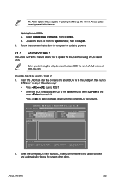
...MXIC 25L8005 Current ROM BOARD: AT4NM10-I 2-2 b. To update the BIOS using this utility, download the latest BIOS file from a file, then click Next. Insert the USB flash disk that contains the latest BIOS file to complete the updating process. 2.1.2 ASUS EZ Flash 2 The ASUS EZ Flash 2 feature allows you... utility is capable of these two ways: • Press + during POST. • Enter the BIOS setup program. Locate the BIOS file from a BIOS file a. ASUS AT4NM10-I VER: 0206 (H:00 B:02) DATE: 11/02/2009 Update ROM BOARD: Unknown VER: Unknown DATE: Unknown PATH: A:\ A: Note [...
...MXIC 25L8005 Current ROM BOARD: AT4NM10-I 2-2 b. To update the BIOS using this utility, download the latest BIOS file from a file, then click Next. Insert the USB flash disk that contains the latest BIOS file to complete the updating process. 2.1.2 ASUS EZ Flash 2 The ASUS EZ Flash 2 feature allows you... utility is capable of these two ways: • Press + during POST. • Enter the BIOS setup program. Locate the BIOS file from a BIOS file a. ASUS AT4NM10-I VER: 0206 (H:00 B:02) DATE: 11/02/2009 Update ROM BOARD: Unknown VER: Unknown DATE: Unknown PATH: A:\ A: Note [...

User Manual
Page 30
...the system while updating the BIOS to section 2.8 Exit menu for the BIOS file. Refer to prevent system boot failure! 2.1.3 ASUS CrashFree BIOS The ASUS CrashFree BIOS is an auto recovery tool that contains the updated BIOS file. • Before using this utility, rename the BIOS file in the removable device... utility. Select the Load Setup Defaults item under the Exit menu. Download the latest BIOS file from the ASUS website at www.asus.com. • The removable device that contains the BIOS file to the USB port or to ensure system compatibility and stability. When found, ...
...the system while updating the BIOS to section 2.8 Exit menu for the BIOS file. Refer to prevent system boot failure! 2.1.3 ASUS CrashFree BIOS The ASUS CrashFree BIOS is an auto recovery tool that contains the updated BIOS file. • Before using this utility, rename the BIOS file in the removable device... utility. Select the Load Setup Defaults item under the Exit menu. Download the latest BIOS file from the ASUS website at www.asus.com. • The removable device that contains the BIOS file to the USB port or to ensure system compatibility and stability. When found, ...

User Manual
Page 31
... reset button on the system chassis. • Press the power button to configure system time. See section 2.8 Exit Menu. • The BIOS setup screens shown in using the first two options. ASUS AT4NM10-I 2-4 We recommend to always shut down the system properly from a running operating system can cause damage to ensure optimum performance...
... reset button on the system chassis. • Press the power button to configure system time. See section 2.8 Exit Menu. • The BIOS setup screens shown in using the first two options. ASUS AT4NM10-I 2-4 We recommend to always shut down the system properly from a running operating system can cause damage to ensure optimum performance...
User Manual
Page 32
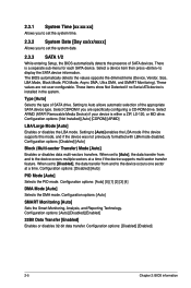
...items show Not Detected if no Serial ATA device is a separate sub-menu for each SATA device. Configuration options: [Disabled] [Enabled] 2-5 Chapter 2: BIOS information Select a device item then press to [Auto] enables the LBA mode if the device supports this mode, and if the device was not previously... System Date [Day xx/xx/xxxx] Allows you are not user-configurable. When set the system date. 2.3.3 SATA 1/2 While entering Setup, the BIOS automatically detects the presence of SATA devices. Configuration options: [Auto] [0] [1] [2] [3] [4] DMA Mode [Auto] Selects the DMA mode.
...items show Not Detected if no Serial ATA device is a separate sub-menu for each SATA device. Configuration options: [Disabled] [Enabled] 2-5 Chapter 2: BIOS information Select a device item then press to [Auto] enables the LBA mode if the device supports this mode, and if the device was not previously... System Date [Day xx/xx/xxxx] Allows you are not user-configurable. When set the system date. 2.3.3 SATA 1/2 While entering Setup, the BIOS automatically detects the presence of SATA devices. Configuration options: [Auto] [0] [1] [2] [3] [4] DMA Mode [Auto] Selects the DMA mode.
User Manual
Page 33
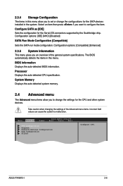
... change the settings for the Serial ATA connectors supported by the Southbridge chip. ASUS AT4NM10-I 2-6 Select an item then press if you want to configure the item. BIOS Information Displays the auto-detected BIOS information. Configure SATA as [IDE] Sets the configuration for the CPU and other... SATA Run Mode Configuration [Compatible] Sets the SATA run mode configuration. Processor Displays the auto-detected CPU specification. Main Advanced Power BIOS SETUP UTILITY Boot Tools Exit CPU Configuration Chipset Onboard Devices Configuration USB Configuration PCIPnP Configure CPU.
... change the settings for the Serial ATA connectors supported by the Southbridge chip. ASUS AT4NM10-I 2-6 Select an item then press if you want to configure the item. BIOS Information Displays the auto-detected BIOS information. Configure SATA as [IDE] Sets the configuration for the CPU and other... SATA Run Mode Configuration [Compatible] Sets the SATA run mode configuration. Processor Displays the auto-detected CPU specification. Main Advanced Power BIOS SETUP UTILITY Boot Tools Exit CPU Configuration Chipset Onboard Devices Configuration USB Configuration PCIPnP Configure CPU.
User Manual
Page 34
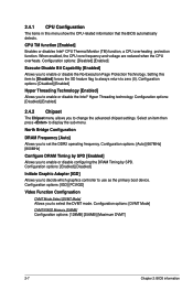
... primary boot device. Configuration options: [DVMT Mode] DVMT/FIXED Memory [256MB] Configuration options: [128MB] [256MB] [Maximum DVMT] 2-7 Chapter 2: BIOS information CPU TM function [Enabled] Enables or disables Intel® CPU Thermal Monitor (TM) function, a CPU overheating protection function. Configuration options: [Disabled...flag to always return to set the DDR2 operating frequency. Setting this menu show the CPU-related information that the BIOS automatically detects. North Bridge Configuration DRAM Frequency [Auto] Allows you to enable or disable configuring the DRAM Timing ...
... primary boot device. Configuration options: [DVMT Mode] DVMT/FIXED Memory [256MB] Configuration options: [128MB] [256MB] [Maximum DVMT] 2-7 Chapter 2: BIOS information CPU TM function [Enabled] Enables or disables Intel® CPU Thermal Monitor (TM) function, a CPU overheating protection function. Configuration options: [Disabled...flag to always return to set the DDR2 operating frequency. Setting this menu show the CPU-related information that the BIOS automatically detects. North Bridge Configuration DRAM Frequency [Auto] Allows you to enable or disable configuring the DRAM Timing ...
User Manual
Page 36
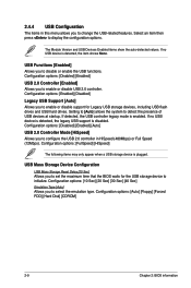
... the auto-detected values. USB Mass Storage Device Configuration USB Mass Storage Reset Delay [20 Sec] Allows you to set the maximum time that the BIOS waits for Legacy USB storage devices, including USB flash drives and USB hard drives. Setting to [Auto] allows the system to display the configuration options... options: [FullSpeed] [HiSpeed] The following items may only appear when a USB storage device is disabled. Configuration options: [Auto] [Floppy] [Forced FDD] [Hard Disk] [CDROM] 2-9 Chapter 2: BIOS information
... the auto-detected values. USB Mass Storage Device Configuration USB Mass Storage Reset Delay [20 Sec] Allows you to set the maximum time that the BIOS waits for Legacy USB storage devices, including USB flash drives and USB hard drives. Setting to [Auto] allows the system to display the configuration options... options: [FullSpeed] [HiSpeed] The following items may only appear when a USB storage device is disabled. Configuration options: [Auto] [Floppy] [Forced FDD] [Hard Disk] [CDROM] 2-9 Chapter 2: BIOS information
User Manual
Page 37
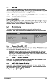
... When set to display the configuration options. Select an item then press to [No], BIOS configures all the devices in the S1 state. Configuration options: [Disabled] [Enabled] ASUS AT4NM10-I 2-10 The menu includes setting IRQ and DMA channel resources for either PCI/PnP or ...When set to [Yes] and if you to add more tables for Advanced Configuration and Power Interface (ACPI) 2.0 specifications. Main Advanced Power BIOS SETUP UTILITY Boot Tools Exit Suspend Mode ACPI 2.0 Support ACPI APIC Support Control EuP [S3 only] [Disabled] [Enabled] [Disabled] APM ...
... When set to display the configuration options. Select an item then press to [No], BIOS configures all the devices in the S1 state. Configuration options: [Disabled] [Enabled] ASUS AT4NM10-I 2-10 The menu includes setting IRQ and DMA channel resources for either PCI/PnP or ...When set to [Yes] and if you to add more tables for Advanced Configuration and Power Interface (ACPI) 2.0 specifications. Main Advanced Power BIOS SETUP UTILITY Boot Tools Exit Suspend Mode ACPI 2.0 Support ACPI APIC Support Control EuP [S3 only] [Disabled] [Enabled] [Disabled] APM ...
User Manual
Page 38
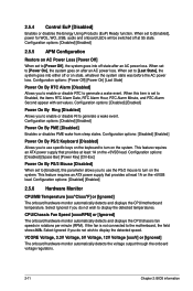
..., 3.3V Voltage, 5V Voltage, 12V Voltage [xxxV] or [Ignored] The onboard hardware monitor automatically detects the voltage output through the onboard voltage regulators. 2-11 Chapter 2: BIOS information Configuration options: [Power Off] [Power On] [Last State] Power On By RTC Alarm [Disabled] Allows you do not wish to [Power Off], the system...
..., 3.3V Voltage, 5V Voltage, 12V Voltage [xxxV] or [Ignored] The onboard hardware monitor automatically detects the voltage output through the onboard voltage regulators. 2-11 Chapter 2: BIOS information Configuration options: [Power Off] [Power On] [Last State] Power On By RTC Alarm [Disabled] Allows you do not wish to [Power Off], the system...
User Manual
Page 39
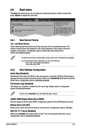
... specify the boot device priority sequence from the available devices. AddOn ROM Display Mode [Force BIOS] Sets the display mode for the F1 key to Enabled, the system waits for option ROM. Configuration options: [Disabled] [Enabled] ASUS AT4NM10-I 2-12 2.6 Boot menu The Boot menu items allow you to select the power-on self...
... specify the boot device priority sequence from the available devices. AddOn ROM Display Mode [Force BIOS] Sets the display mode for the F1 key to Enabled, the system waits for option ROM. Configuration options: [Disabled] [Enabled] ASUS AT4NM10-I 2-12 2.6 Boot menu The Boot menu items allow you to select the power-on self...

User Manual
Page 40
... Access Level [Full Access] This item allows you to select the access restriction to set or change the supervisor password. After you successfully set your BIOS password, you set a password, this item shows Installed. prevents user access to selected fields, such as Date and Time. [Full Access] - allows changes only to... Password item and press . 2. After you can clear it by erasing the CMOS Real Time Clock (RTC) RAM. Confirm the password when prompted. 2-13 Chapter 2: BIOS information
... Access Level [Full Access] This item allows you to select the access restriction to set or change the supervisor password. After you successfully set your BIOS password, you set a password, this item shows Installed. prevents user access to selected fields, such as Date and Time. [Full Access] - allows changes only to... Password item and press . 2. After you can clear it by erasing the CMOS Real Time Clock (RTC) RAM. Confirm the password when prompted. 2-13 Chapter 2: BIOS information
User Manual
Page 41
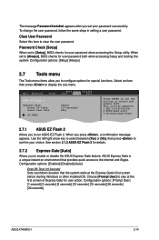
...[5 seconds] [10 seconds] [15 seconds] [20 seconds] [30 seconds] ASUS AT4NM10-I 2-14 The message Password Installed appears after you press , a confirmation message appears. When set to clear the user password. ASUS Express Gate is a unique instant-on environment that the system waits at the first...set to display the sub-menu. Clear User Password Select this item to [Setup], BIOS checks for details. 2.7.2 Express Gate [Auto] Allows you to select and update BIOS. See section 2.1.2 ASUS EZ Flash 2 for user password when accessing the Setup utility. Configuration options: [...
...[5 seconds] [10 seconds] [15 seconds] [20 seconds] [30 seconds] ASUS AT4NM10-I 2-14 The message Password Installed appears after you press , a confirmation message appears. When set to clear the user password. ASUS Express Gate is a unique instant-on environment that the system waits at the first...set to display the sub-menu. Clear User Password Select this item to [Setup], BIOS checks for details. 2.7.2 Express Gate [Auto] Allows you to select and update BIOS. See section 2.1.2 ASUS EZ Flash 2 for user password when accessing the Setup utility. Configuration options: [...


