
Hardware Reference
Page 5
... Solutions 31 iv. Appendix i. Power Supply 27 Removing the Power Supply 27 ATX Power Button 27 4-10. ASUS Barebone Servers 32 AP200 Hardware Reference Guide 5 Long Card Guide 26 4-8. Motherboard 19 Motherboard Screws 19 Chassis Intrusion Photo Sensor 20 Panel Connections 20 4-3. 3.5" Device Cage 21 3.5" Device Cage Removal Procedure 21 Floppy Disk Drive Mounting...
... Solutions 31 iv. Appendix i. Power Supply 27 Removing the Power Supply 27 ATX Power Button 27 4-10. ASUS Barebone Servers 32 AP200 Hardware Reference Guide 5 Long Card Guide 26 4-8. Motherboard 19 Motherboard Screws 19 Chassis Intrusion Photo Sensor 20 Panel Connections 20 4-3. 3.5" Device Cage 21 3.5" Device Cage Removal Procedure 21 Floppy Disk Drive Mounting...
Hardware Reference
Page 7
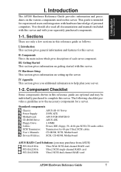
Introduction The AP200 Hardware Reference Guide provides information and procedures on getting started with this reference guide as to the necessary components for 68-pin Ultra2 SCSI cables CD-ROM, SCSI, Motherboard SCSI, CD-ROM, Motherboard ASUS RAID Card Solutions (you additional information to complete this server. You should also read all documentation and manuals...
Introduction The AP200 Hardware Reference Guide provides information and procedures on getting started with this reference guide as to the necessary components for 68-pin Ultra2 SCSI cables CD-ROM, SCSI, Motherboard SCSI, CD-ROM, Motherboard ASUS RAID Card Solutions (you additional information to complete this server. You should also read all documentation and manuals...
Hardware Reference
Page 8
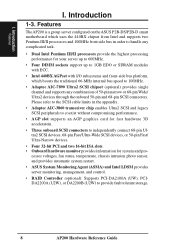
Features The AP200 is a group server configured on the ASUS P2B-DS/P2B-D smart motherboard which uses the 440BX chipset from Intel and supports two Pentium III/II processors and 100MHz front side bus in the appendix. • ...bus platform, which boosts the traditional 66-MHz internal bus speed to provide fault tolerant storage. 8 AP200 Hardware Reference Guide cessor voltages, fan status, temperature, chassis intrusion photo sensor, and provides automatic system restart. • ASUS System Monitoring Agent (ASMA) and Intel LDSM provides server monitoring, management, and control. •...
Features The AP200 is a group server configured on the ASUS P2B-DS/P2B-D smart motherboard which uses the 440BX chipset from Intel and supports two Pentium III/II processors and 100MHz front side bus in the appendix. • ...bus platform, which boosts the traditional 66-MHz internal bus speed to provide fault tolerant storage. 8 AP200 Hardware Reference Guide cessor voltages, fan status, temperature, chassis intrusion photo sensor, and provides automatic system restart. • ASUS System Monitoring Agent (ASMA) and Intel LDSM provides server monitoring, management, and control. •...

Hardware Reference
Page 10
... cable from the electrical outlet before you need to lay the device down while it is equipped with different electrical potentials. Static-Sensitive Devices IMPORTANT Motherboards, adapters, and disk drives are wrapped in its antistatic bag, touch it on the antistatic bag. Hold drives by the edges. Before picking it while... strap available, use it up again, touch the antistatic bag and the metal frame of the antistatic bag, lay it to prevent permanent damage. 10 AP200 Hardware Reference Guide
... cable from the electrical outlet before you need to lay the device down while it is equipped with different electrical potentials. Static-Sensitive Devices IMPORTANT Motherboards, adapters, and disk drives are wrapped in its antistatic bag, touch it on the antistatic bag. Hold drives by the edges. Before picking it while... strap available, use it up again, touch the antistatic bag and the metal frame of the antistatic bag, lay it to prevent permanent damage. 10 AP200 Hardware Reference Guide
Hardware Reference
Page 11
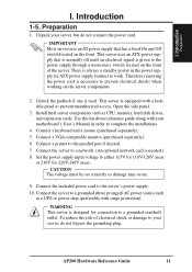
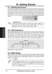
...network. (An optional network card is equipped with a lockable panel to complete the installations. 4. To reduce the risk of the server. Unpack your motherboard's User's Manual in the power supply for ATX power supply features to a grounded (earthed) outlet. This server is needed.) 8. Use this ...for 110V-120V areas or 230V for connection to work. Preparation 1. Connect the included power cord to the parallel port if desired. 7. AP200 Hardware Reference Guide 11 There is necessary to a grounded (three pronged) AC power source such as CPU, memory, hard disk drives, ...
...network. (An optional network card is equipped with a lockable panel to complete the installations. 4. To reduce the risk of the server. Unpack your motherboard's User's Manual in the power supply for ATX power supply features to a grounded (earthed) outlet. This server is needed.) 8. Use this ...for 110V-120V areas or 230V for connection to work. Preparation 1. Connect the included power cord to the parallel port if desired. 7. AP200 Hardware Reference Guide 11 There is necessary to a grounded (three pronged) AC power source such as CPU, memory, hard disk drives, ...
Hardware Reference
Page 14
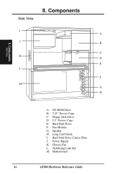
Floppy Disk Drive D. 3.5" Device Cage E. Motherboard 14 AP200 Hardware Reference Guide Components I . Fan Module G. Long Card Guide I A J B C K D E L F M G H A. Hard Disk Drive Carrier Plate J. CD-ROM Drive B. 5.25" Device Cage C. Hard Disk Drive F. Power Supply K. Chassis Fan L. II. Components Side View Side View II. Speaker H. Stabilizing Link Bar M.
Floppy Disk Drive D. 3.5" Device Cage E. Motherboard 14 AP200 Hardware Reference Guide Components I . Fan Module G. Long Card Guide I A J B C K D E L F M G H A. Hard Disk Drive Carrier Plate J. CD-ROM Drive B. 5.25" Device Cage C. Hard Disk Drive F. Power Supply K. Chassis Fan L. II. Components Side View Side View II. Speaker H. Stabilizing Link Bar M.
Hardware Reference
Page 16
...your ACPI OS and software. Getting Started Startup / LED / BIOS LED Indicators on the system unit by pressing before Setup begins. 16 AP200 Hardware Reference Guide LED Indicators Three green LED indicators are located on the top of the modem, fax, email, or voice mail as determined...not come with any pre-installed software. When lit, the "Message" shows the status of the front panel. "Power On" lights when the motherboard receives power from the power supply. 3-2. NOTE When installing Windows NT 4.0 or higher operation system, use the Windows NT installation floppy disks. ...
...your ACPI OS and software. Getting Started Startup / LED / BIOS LED Indicators on the system unit by pressing before Setup begins. 16 AP200 Hardware Reference Guide LED Indicators Three green LED indicators are located on the top of the modem, fax, email, or voice mail as determined...not come with any pre-installed software. When lit, the "Message" shows the status of the front panel. "Power On" lights when the motherboard receives power from the power supply. 3-2. NOTE When installing Windows NT 4.0 or higher operation system, use the Windows NT installation floppy disks. ...
Hardware Reference
Page 19
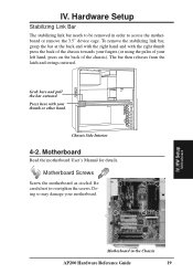
.... IV. Hardware Setup Stabilizing Link Bar The stabilizing link bar needs to be removed in the Chassis AP200 Hardware Reference Guide 19 HW Setup Motherboard Motherboard in order to overtighten the screws. To remove the stabilizing link bar, grasp the bar at the ... end with the right hand and with your motherboard. Be careful not to access the motherboard or remove the 3.5" device cage. IV. Grab here and pull the bar outward. Motherboard Screws Screw the motherboard as circled. Chassis Side Interior 4-2. Motherboard Read the motherboard User's Manual for details.
.... IV. Hardware Setup Stabilizing Link Bar The stabilizing link bar needs to be removed in the Chassis AP200 Hardware Reference Guide 19 HW Setup Motherboard Motherboard in order to overtighten the screws. To remove the stabilizing link bar, grasp the bar at the ... end with the right hand and with your motherboard. Be careful not to access the motherboard or remove the 3.5" device cage. IV. Grab here and pull the bar outward. Motherboard Screws Screw the motherboard as circled. Chassis Side Interior 4-2. Motherboard Read the motherboard User's Manual for details.
Hardware Reference
Page 20
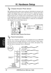
... Photo Sensor Panel Connections Several wires should disable Jumper18 to the ASMA software in such an event. Panel connections also allow for motherboard BIOS and clock White Black White Chassis Panel Connectors JP18 EXTBATT IR Green White Red Violet White Red Black Yellow White Red (+)... SW Black Yellow (+) Turbo LED White Green (+) Power LED White 20 AP200 Hardware Reference Guide Connect the chassis front panel wires as when the chassis is connected, you should be connected to the motherboard for the IDE/SCSI activity, power, and message indicators on the inside ...
... Photo Sensor Panel Connections Several wires should disable Jumper18 to the ASMA software in such an event. Panel connections also allow for motherboard BIOS and clock White Black White Chassis Panel Connectors JP18 EXTBATT IR Green White Red Violet White Red Black Yellow White Red (+)... SW Black Yellow (+) Turbo LED White Green (+) Power LED White 20 AP200 Hardware Reference Guide Connect the chassis front panel wires as when the chassis is connected, you should be connected to the motherboard for the IDE/SCSI activity, power, and message indicators on the inside ...
Hardware Reference
Page 24
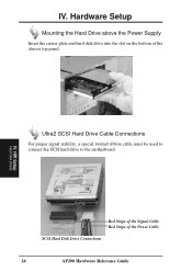
IV. HW Setup Hard Disk Drives Ultra2 SCSI Hard Drive Cable Connections For proper signal stability, a special twisted ribbon cable must be used to connect the SCSI hard drive to the motherboard. Hardware Setup Mounting the Hard Drive above the Power Supply Insert the carrier plate and hard disk drive into the slot on the bottom of the Power Cable SCSI Hard Disk Drive Connections 24 AP200 Hardware Reference Guide IV. Red Stripe of the Signal Cable Red Stripe of the chassis top panel.
IV. HW Setup Hard Disk Drives Ultra2 SCSI Hard Drive Cable Connections For proper signal stability, a special twisted ribbon cable must be used to connect the SCSI hard drive to the motherboard. Hardware Setup Mounting the Hard Drive above the Power Supply Insert the carrier plate and hard disk drive into the slot on the bottom of the Power Cable SCSI Hard Disk Drive Connections 24 AP200 Hardware Reference Guide IV. Red Stripe of the Signal Cable Red Stripe of the chassis top panel.

Hardware Reference
Page 29
...is unstable over long lengths. If connecting Fast/Ultra devices with Ultra2 devices on the Ultra2 connector, the entire SCSI bus will depend on the motherboard. Ultra-SCSI technology is reserved for individual connectors and do not take into account other connectors. Therefore stability will be connected to the Ultra ... a 3m (9.8ft) cable. 5) A total of the SCSI devices. Exceeding the length may cause problems mounting or using a 3m (9.89ft) cable. Appendix SCSI Cable Limits AP200 Hardware Reference Guide 29 Appendix i. SCSI Cable Limits SCSI cables have . V.
...is unstable over long lengths. If connecting Fast/Ultra devices with Ultra2 devices on the Ultra2 connector, the entire SCSI bus will depend on the motherboard. Ultra-SCSI technology is reserved for individual connectors and do not take into account other connectors. Therefore stability will be connected to the Ultra ... a 3m (9.8ft) cable. 5) A total of the SCSI devices. Exceeding the length may cause problems mounting or using a 3m (9.89ft) cable. Appendix SCSI Cable Limits AP200 Hardware Reference Guide 29 Appendix i. SCSI Cable Limits SCSI cables have . V.

Hardware Reference
Page 30
... CD-R Drive (with external bracket) to the 50-pin narrow connector on the motherboard for routine backups. • The Wide-SCSI connector on the motherboard can be connected to the Ultra2 connector on the motherboard for 18GB of main storage. • One Ultra-SCSI tape drive in the ...5.25" cage is connected to the chassis slot opening for connection of SCSI connections 30 AP200 Hardware Reference Guide V. Appendix ii...
... CD-R Drive (with external bracket) to the 50-pin narrow connector on the motherboard for routine backups. • The Wide-SCSI connector on the motherboard can be connected to the Ultra2 connector on the motherboard for 18GB of main storage. • One Ultra-SCSI tape drive in the ...5.25" cage is connected to the chassis slot opening for connection of SCSI connections 30 AP200 Hardware Reference Guide V. Appendix ii...

