
Hardware Reference
Page 4
... Long Card Guide 15 III. Components 2-1. Getting Started 3-1. BIOS Setup 16 IV. Component Checklist 7 1-3. Starting the Server 16 3-2. System Overview 12 Front View 12 Rear View 13 Side View 14 2-2. LED Indicators 16 3-3. Contents I. Safeguards 9 Operation Safety 9 Tools Required 9 Electrical Safety 10 Static-Sensitive Devices 10 1-5. Chassis 17 Removing the Left Panel 17 Installing the Left Panel 17 Removing the Front & Top Panels 18 Device Bay Covers 18 Stabilizing Link Bar 19 4 AP200 Hardware Reference Guide Introduction 1-1. Hardware Setup...
... Long Card Guide 15 III. Components 2-1. Getting Started 3-1. BIOS Setup 16 IV. Component Checklist 7 1-3. Starting the Server 16 3-2. System Overview 12 Front View 12 Rear View 13 Side View 14 2-2. LED Indicators 16 3-3. Contents I. Safeguards 9 Operation Safety 9 Tools Required 9 Electrical Safety 10 Static-Sensitive Devices 10 1-5. Chassis 17 Removing the Left Panel 17 Installing the Left Panel 17 Removing the Front & Top Panels 18 Device Bay Covers 18 Stabilizing Link Bar 19 4 AP200 Hardware Reference Guide Introduction 1-1. Hardware Setup...
Hardware Reference
Page 5
... Servers 32 AP200 Hardware Reference Guide 5 Contents 4-2. Long Card Guide 26 4-8. Motherboard 19 Motherboard Screws 19 Chassis Intrusion Photo Sensor 20 Panel Connections 20 4-3. 3.5" Device Cage 21 3.5" Device Cage Removal Procedure 21 Floppy Disk Drive Mounting 21 Floppy Disk Drive Cable Connections 22 4-4. 5.25" Device Cage 22 5.25" Device Cage Removal Procedure 22 CD-ROM Drive Mounting and Connections 23 4-5. Air Circulation System 25 Fan Replacement 25 4-7. Appendix i. ASUS RAID Solutions 31 iv. SCSI Connection Example 30 iii. Hard Disk Drives 23 Hard...
... Servers 32 AP200 Hardware Reference Guide 5 Contents 4-2. Long Card Guide 26 4-8. Motherboard 19 Motherboard Screws 19 Chassis Intrusion Photo Sensor 20 Panel Connections 20 4-3. 3.5" Device Cage 21 3.5" Device Cage Removal Procedure 21 Floppy Disk Drive Mounting 21 Floppy Disk Drive Cable Connections 22 4-4. 5.25" Device Cage 22 5.25" Device Cage Removal Procedure 22 CD-ROM Drive Mounting and Connections 23 4-5. Air Circulation System 25 Fan Replacement 25 4-7. Appendix i. ASUS RAID Solutions 31 iv. SCSI Connection Example 30 iii. Hard Disk Drives 23 Hard...

Hardware Reference
Page 6
.... 6 AP200 Hardware Reference Guide If this equipment. These limits are designed to provide reasonable protection against harmful interference in the Radio Interference Regulations of the Canadian Department of Communications. The use of shielded cables for help. Changes or modifications to this unit not expressly approved by one or more of the monitor to the graphics card is connected. •...
.... 6 AP200 Hardware Reference Guide If this equipment. These limits are designed to provide reasonable protection against harmful interference in the Radio Interference Regulations of the Canadian Department of Communications. The use of shielded cables for help. Changes or modifications to this unit not expressly approved by one or more of the monitor to the graphics card is connected. •...
Hardware Reference
Page 7
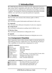
... setting up the server. Introduction This section gives general information and features for a server. Getting Started This section gives information on getting started with this server. Sections There are optional and may purchase from ASUS) PCI-DA2100A: Ultra-Wide SCSI dual-channel RAID card PCI-DA2200A: Ultra2 SCSI single-channel RAID card PCI-DA2200B: Ultra2 SCSI dual-channel RAID card AP200 Hardware Reference Guide 7 Standard components Chassis: Power Supply: Motherboard: CD-ROM Drive: Floppy Drive: Cables: SCSI Terminator: User's Manuals: Drivers/Utilities: ASUS...
... setting up the server. Introduction This section gives general information and features for a server. Getting Started This section gives information on getting started with this server. Sections There are optional and may purchase from ASUS) PCI-DA2100A: Ultra-Wide SCSI dual-channel RAID card PCI-DA2200A: Ultra2 SCSI single-channel RAID card PCI-DA2200B: Ultra2 SCSI dual-channel RAID card AP200 Hardware Reference Guide 7 Standard components Chassis: Power Supply: Motherboard: CD-ROM Drive: Floppy Drive: Cables: SCSI Terminator: User's Manuals: Drivers/Utilities: ASUS...
Hardware Reference
Page 8
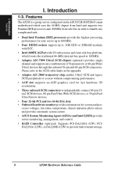
... SCSI connectors. Please refer to the SCSI cable limits in order to provide fault tolerant storage. 8 AP200 Hardware Reference Guide Introduction 1-3. cessor voltages, fan status, temperature, chassis intrusion photo sensor, and provides automatic system restart. • ASUS System Monitoring Agent (ASMA) and Intel LDSM provides server monitoring, management, and control. • RAID Controller (optional): Supports PCI-DA2100A (UW), PCIDA2200A (U2W), or DA2200B (U2W) to handle any complicated task. • Dual Intel Pentium III/II processors...
... SCSI connectors. Please refer to the SCSI cable limits in order to provide fault tolerant storage. 8 AP200 Hardware Reference Guide Introduction 1-3. cessor voltages, fan status, temperature, chassis intrusion photo sensor, and provides automatic system restart. • ASUS System Monitoring Agent (ASMA) and Intel LDSM provides server monitoring, management, and control. • RAID Controller (optional): Supports PCI-DA2100A (UW), PCIDA2200A (U2W), or DA2200B (U2W) to handle any complicated task. • Dual Intel Pentium III/II processors...
Hardware Reference
Page 9
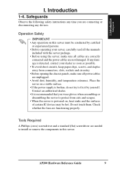
... not try to protect from connectors, slots, sockets and circuitry. • Before opening the chassis panels, make sure all power cables are not damaged. Place the server on a stable surface. • If the power supply is powered on this server. Tools Required A Phillips (cross) screwdriver and a standard (flat) screwdriver are functioning properly. Safeguards Observe the following safety instructions any time you wear gloves when...
... not try to protect from connectors, slots, sockets and circuitry. • Before opening the chassis panels, make sure all power cables are not damaged. Place the server on a stable surface. • If the power supply is powered on this server. Tools Required A Phillips (cross) screwdriver and a standard (flat) screwdriver are functioning properly. Safeguards Observe the following safety instructions any time you wear gloves when...

Hardware Reference
Page 11
... a network. (An optional network card is necessary to work. Therefore removing the power cord is needed.) 8. Set the power supply input voltage to prevent unauthorized access. This server is given to the parallel port if desired. 7. Use this hardware reference guide along with surge protection). Connect the server to complete the installations. 4. CAUTION The voltage must be set correctly or damage may occur. 9. Connect the server to your server, do not connect the power cord...
... a network. (An optional network card is necessary to work. Therefore removing the power cord is needed.) 8. Set the power supply input voltage to prevent unauthorized access. This server is given to the parallel port if desired. 7. Use this hardware reference guide along with surge protection). Connect the server to complete the installations. 4. CAUTION The voltage must be set correctly or damage may occur. 9. Connect the server to your server, do not connect the power cord...
Hardware Reference
Page 14
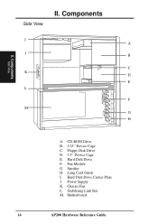
Floppy Disk Drive D. 3.5" Device Cage E. Hard Disk Drive F. Long Card Guide I A J B C K D E L F M G H A. Power Supply K. Chassis Fan L. Stabilizing Link Bar M. II. CD-ROM Drive B. 5.25" Device Cage C. Hard Disk Drive Carrier Plate J. Motherboard 14 AP200 Hardware Reference Guide Speaker H. Components Side View Side View II. Components I . Fan Module G.
Floppy Disk Drive D. 3.5" Device Cage E. Hard Disk Drive F. Long Card Guide I A J B C K D E L F M G H A. Power Supply K. Chassis Fan L. Stabilizing Link Bar M. II. CD-ROM Drive B. 5.25" Device Cage C. Hard Disk Drive Carrier Plate J. Motherboard 14 AP200 Hardware Reference Guide Speaker H. Components Side View Side View II. Components I . Fan Module G.

Hardware Reference
Page 15
... top of the server. System Speaker This server has a standard speaker for mounting three 5.25" devices such as CDROM, tape, and hard disk drives. 3.5" Device Cage The 3.5" device cage is necessary to secure the 5.25" and 3.5" device cages. It can be turned clockwise to the power supply through the front. AP200 Hardware Reference Guide 15 Chassis Features 5.25" Device Cage The 5.25" device cage is used for error notifications and other...
... top of the server. System Speaker This server has a standard speaker for mounting three 5.25" devices such as CDROM, tape, and hard disk drives. 3.5" Device Cage The 3.5" device cage is necessary to secure the 5.25" and 3.5" device cages. It can be turned clockwise to the power supply through the front. AP200 Hardware Reference Guide 15 Chassis Features 5.25" Device Cage The 5.25" device cage is used for error notifications and other...
Hardware Reference
Page 16
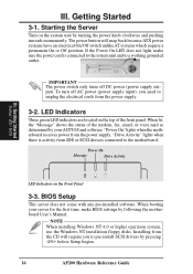
..., the "Message" shows the status of the front panel. Power On Message Drive Activity III. NOTE When installing Windows NT 4.0 or higher operation system, use the Windows NT installation floppy disks. Getting Started Startup / LED / BIOS LED Indicators on the top of the modem, fax, email, or voice mail as determined by following the motherboard User's Manual. LED Indicators Three green LED indicators are located on the Front Panel 3-3. "Drive Activity" lights when there is connected to...
..., the "Message" shows the status of the front panel. Power On Message Drive Activity III. NOTE When installing Windows NT 4.0 or higher operation system, use the Windows NT installation floppy disks. Getting Started Startup / LED / BIOS LED Indicators on the top of the modem, fax, email, or voice mail as determined by following the motherboard User's Manual. LED Indicators Three green LED indicators are located on the Front Panel 3-3. "Drive Activity" lights when there is connected to...

Hardware Reference
Page 17
... from the front panel. 2. Chassis Removing the Left Panel The left panel towards the front panel. Slide the left panel needs to be removed to gain access to the internal system. Pull the bottom of the left panel is used on the hooks by the edge of the left panel. 3. Push the bottom of the top panel. AP200 Hardware Reference Guide 17 IV. IV. Remove the thumb screw on...
... from the front panel. 2. Chassis Removing the Left Panel The left panel towards the front panel. Slide the left panel needs to be removed to gain access to the internal system. Pull the bottom of the left panel is used on the hooks by the edge of the left panel. 3. Push the bottom of the top panel. AP200 Hardware Reference Guide 17 IV. IV. Remove the thumb screw on...

Hardware Reference
Page 18
... into the front panel and pull the front panel away from the front side. Device Bay Cover Tab Front Panel Backside 18 AP200 Hardware Reference Guide Lean the front panel over the edge of the front panel. 2. IV. Device Bay Covers With the front panel removed, the device bay covers can be unscrewed and removed. Hardware Setup Removing the Front & Top Panels Before removing the front panel, the top panel must be removed or installed. Device Bay Removal Procedure: 1.
... into the front panel and pull the front panel away from the front side. Device Bay Cover Tab Front Panel Backside 18 AP200 Hardware Reference Guide Lean the front panel over the edge of the front panel. 2. IV. Device Bay Covers With the front panel removed, the device bay covers can be unscrewed and removed. Hardware Setup Removing the Front & Top Panels Before removing the front panel, the top panel must be removed or installed. Device Bay Removal Procedure: 1.
Hardware Reference
Page 20
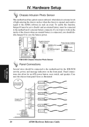
... detects extreme levels of the chassis when an external battery is opened, and sends a signal to the motherboard for the IDE/SCSI activity, power, and message indicators on the inside of light entering the chassis such as illustrated: Button Cell Battery for an ATX power button, reset switch, and speaker. To enable this function, Jumper18 must be set to Enable and an external battery must be connected to the ASMA software in...
... detects extreme levels of the chassis when an external battery is opened, and sends a signal to the motherboard for the IDE/SCSI activity, power, and message indicators on the inside of light entering the chassis such as illustrated: Button Cell Battery for an ATX power button, reset switch, and speaker. To enable this function, Jumper18 must be set to Enable and an external battery must be connected to the ASMA software in...

Hardware Reference
Page 22
... alignment and insertion is made. Align the red stripes of power cable 1.44MB Floppy Disk Drive Connections 4-4. 5.25" Device Cage Before CD-ROM, tape, or hard disk drives can be installed or removed from the 5.25" device cage, you must remove the device cage from the chassis. 5.25" Device Cage Removal Procedure 1. Pull the device cage to the left side of the chassis. IV. Hardware Setup Floppy Disk Drive Cable Connections The 1.44MB floppy disk drive requires signal and power connections.
... alignment and insertion is made. Align the red stripes of power cable 1.44MB Floppy Disk Drive Connections 4-4. 5.25" Device Cage Before CD-ROM, tape, or hard disk drives can be installed or removed from the 5.25" device cage, you must remove the device cage from the chassis. 5.25" Device Cage Removal Procedure 1. Pull the device cage to the left side of the chassis. IV. Hardware Setup Floppy Disk Drive Cable Connections The 1.44MB floppy disk drive requires signal and power connections.

Hardware Reference
Page 23
... cable. HW Setup Hard Disk Drives Hard Disk Drive Mounted on the bottom of the power supply is used to your audio card. The handle faces upward. Red Stripe of the Signal Cable Red Stripe of the signal and power cables should face each other. Hard Disk Drives Hard Disk Drive Carrier Plate A carrier plate on top of the carrier plate as shown. Hardware Setup CD-ROM Drive Mounting and Connections The CD-ROM disk drive mounts only in this direction. AP200 Hardware Reference Guide...
... cable. HW Setup Hard Disk Drives Hard Disk Drive Mounted on the bottom of the power supply is used to your audio card. The handle faces upward. Red Stripe of the Signal Cable Red Stripe of the signal and power cables should face each other. Hard Disk Drives Hard Disk Drive Carrier Plate A carrier plate on top of the carrier plate as shown. Hardware Setup CD-ROM Drive Mounting and Connections The CD-ROM disk drive mounts only in this direction. AP200 Hardware Reference Guide...
Hardware Reference
Page 24
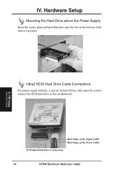
IV. IV. HW Setup Hard Disk Drives Ultra2 SCSI Hard Drive Cable Connections For proper signal stability, a special twisted ribbon cable must be used to connect the SCSI hard drive to the motherboard. Hardware Setup Mounting the Hard Drive above the Power Supply Insert the carrier plate and hard disk drive into the slot on the bottom of the Power Cable SCSI Hard Disk Drive Connections 24 AP200 Hardware Reference Guide Red Stripe of the Signal Cable Red Stripe of the chassis top panel.
IV. IV. HW Setup Hard Disk Drives Ultra2 SCSI Hard Drive Cable Connections For proper signal stability, a special twisted ribbon cable must be used to connect the SCSI hard drive to the motherboard. Hardware Setup Mounting the Hard Drive above the Power Supply Insert the carrier plate and hard disk drive into the slot on the bottom of the Power Cable SCSI Hard Disk Drive Connections 24 AP200 Hardware Reference Guide Red Stripe of the Signal Cable Red Stripe of the chassis top panel.
Hardware Reference
Page 26
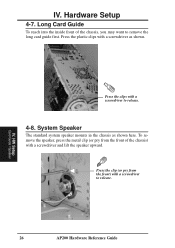
... mounts in the chassis as shown. Press the clip (or pry from the front of the chassis, you may want to remove the long card guide first. IV. Hardware Setup 4-7. IV. To remove... the speaker, press the metal clip (or pry from the front) with a screwdriver as shown here. Press the plastic clips with a screwdriver to release. 4-8. Long Card Guide To reach into the inside front of the chassis) with a screwdriver to release. 26 AP200 Hardware Reference Guide HW Setup Card Guide...
... mounts in the chassis as shown. Press the clip (or pry from the front of the chassis, you may want to remove the long card guide first. IV. Hardware Setup 4-7. IV. To remove... the speaker, press the metal clip (or pry from the front) with a screwdriver as shown here. Press the plastic clips with a screwdriver to release. 4-8. Long Card Guide To reach into the inside front of the chassis) with a screwdriver to release. 26 AP200 Hardware Reference Guide HW Setup Card Guide...

Hardware Reference
Page 29
... problems mounting or using a 3m (9.89ft) cable. Ultra-SCSI technology is reserved for individual connectors and do not take into account other connectors. SCSI Cable Limits SCSI cables have . Appendix SCSI Cable Limits AP200 Hardware Reference Guide 29 Mixing SCSI devices is not recommended. 2) A total of 7 "Wide Ultra-SCSI" devices (ID0-ID15) may be connected to the 68-pin Wide connector if using a 1.5m (4.9ft) cable, but only 4 devices when using a 3m (9.8ft) cable. 5) A total of the SCSI devices...
... problems mounting or using a 3m (9.89ft) cable. Ultra-SCSI technology is reserved for individual connectors and do not take into account other connectors. SCSI Cable Limits SCSI cables have . Appendix SCSI Cable Limits AP200 Hardware Reference Guide 29 Mixing SCSI devices is not recommended. 2) A total of 7 "Wide Ultra-SCSI" devices (ID0-ID15) may be connected to the 68-pin Wide connector if using a 1.5m (4.9ft) cable, but only 4 devices when using a 3m (9.8ft) cable. 5) A total of the SCSI devices...

Hardware Reference
Page 30
... of how SCSI devices can be connected to your server. • Two 9GB Ultra2-SCSI hard disks in the 3.5" cage can be connected to the Ultra2 connector on the motherboard for 18GB of main storage. • One Ultra-SCSI tape drive in the 5.25" cage is connected to the chassis slot opening for connection of SCSI connections 30 AP200 Hardware Reference Guide V. V. Appendix SCSI Cabling Example of an external 4GB Ultra-Wide hard disk drive and a Wide-SCSI CD...
... of how SCSI devices can be connected to your server. • Two 9GB Ultra2-SCSI hard disks in the 3.5" cage can be connected to the Ultra2 connector on the motherboard for 18GB of main storage. • One Ultra-SCSI tape drive in the 5.25" cage is connected to the chassis slot opening for connection of SCSI connections 30 AP200 Hardware Reference Guide V. V. Appendix SCSI Cabling Example of an external 4GB Ultra-Wide hard disk drive and a Wide-SCSI CD...
Hardware Reference
Page 31
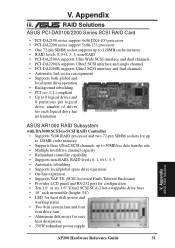
... expansion • Supports SAF-TE (SCSI Accessed Fault-Tolerant Enclosure) • Provides LCD panel and RS-232 port for configuration • Ten 1.0" or six 1.6" Ultra2 SCSI SCA-2 hot-swappable drive bays • 19" rack mountable (height: 5U) • LED for hard disk power and working status • Two 8cm system fans and four 6cm drive fans • Aluminum disk arrays for up to 128MB cache memory • RAID levels 0, 0+1, 3, 5, non-RAID • PCI-DA2100A supports Ultra Wide SCSI interface...
... expansion • Supports SAF-TE (SCSI Accessed Fault-Tolerant Enclosure) • Provides LCD panel and RS-232 port for configuration • Ten 1.0" or six 1.6" Ultra2 SCSI SCA-2 hot-swappable drive bays • 19" rack mountable (height: 5U) • LED for hard disk power and working status • Two 8cm system fans and four 6cm drive fans • Aluminum disk arrays for up to 128MB cache memory • RAID levels 0, 0+1, 3, 5, non-RAID • PCI-DA2100A supports Ultra Wide SCSI interface...


