
User Manual
Page 5
Contents Disclaimer/Copyrights ii ASUS Contact Information iii FCC/CDC Statements iv Safety Precautions vii Electrical Safety vii Operation Safety vii Introduction About this guide I-1 Audience I-2 Contents I-2 Conventions I-3 References I-3 System Package Contents I-4 Chapter 1: System Overview System Overview 1-1 1.1 System Features 1-2 1.2 Front Panel Features 1-3 1.3 Rear Panel Features 1-4 1.4 Internal Features 1-5 1.5 LED Table 1-6 Chapter 2: Hardware Reference Hardware...
Contents Disclaimer/Copyrights ii ASUS Contact Information iii FCC/CDC Statements iv Safety Precautions vii Electrical Safety vii Operation Safety vii Introduction About this guide I-1 Audience I-2 Contents I-2 Conventions I-3 References I-3 System Package Contents I-4 Chapter 1: System Overview System Overview 1-1 1.1 System Features 1-2 1.2 Front Panel Features 1-3 1.3 Rear Panel Features 1-4 1.4 Internal Features 1-5 1.5 LED Table 1-6 Chapter 2: Hardware Reference Hardware...
User Manual
Page 15
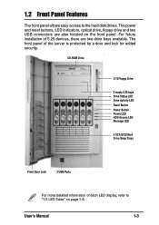
... there are also located on page 1-6. CD-ROM Drive 31/2 Floppy Drive 2 empty 5.25 bays Drive Status LED Drive Activity LED Reset Button Power Button Power LED HDD Access LED Message LED 6 SCA SCSI Hard Drive Swap Trays Front Door Lock 2 USB Ports For more detailed information of the server ...is protected by a door and lock for added security. The front panel of each LED display, refer to the hard disk drives. The power and reset buttons, LED indicators, optical drive, floppy drive and two USB connectors are two drive bays available. User's Manual 1-3...
... there are also located on page 1-6. CD-ROM Drive 31/2 Floppy Drive 2 empty 5.25 bays Drive Status LED Drive Activity LED Reset Button Power Button Power LED HDD Access LED Message LED 6 SCA SCSI Hard Drive Swap Trays Front Door Lock 2 USB Ports For more detailed information of the server ...is protected by a door and lock for added security. The front panel of each LED display, refer to the hard disk drives. The power and reset buttons, LED indicators, optical drive, floppy drive and two USB connectors are two drive bays available. User's Manual 1-3...
User Manual
Page 16
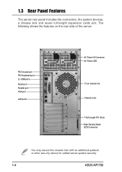
1.3 Rear Panel Features The server rear panel includes the connectors, the system devices, a chassis lock and seven full-length expansion cards slot. The following shows the features on the rear side of the server. PS/2 mouse port PS/2 keyboard port 2 x USB ports Serial port Parallel port VGA port LAN ports AC Power IN Connector AC Power LED 12 cm chassis fan Chassis Lock 7 Full-Length PCI Slots High Density 68-pin SCSI Connector You may secure the chassis lock with an additional padlock or other security device for added server system security. 1-4 ASUS AP1700
1.3 Rear Panel Features The server rear panel includes the connectors, the system devices, a chassis lock and seven full-length expansion cards slot. The following shows the features on the rear side of the server. PS/2 mouse port PS/2 keyboard port 2 x USB ports Serial port Parallel port VGA port LAN ports AC Power IN Connector AC Power LED 12 cm chassis fan Chassis Lock 7 Full-Length PCI Slots High Density 68-pin SCSI Connector You may secure the chassis lock with an additional padlock or other security device for added server system security. 1-4 ASUS AP1700
User Manual
Page 18
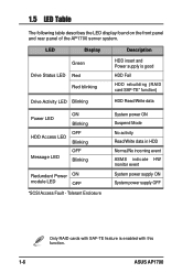
... power supply ON System power supply OFF Only RAID cards with this function. 1-6 ASUS AP1700 1.5 LED Table The following table describes the LED display found on the front panel and rear panel of the AP1700 server system. LED Display Description Green Drive Status LED Red Red blinking HDD insert and Power supply is enabled with SAF-TE...
... power supply ON System power supply OFF Only RAID cards with this function. 1-6 ASUS AP1700 1.5 LED Table The following table describes the LED display found on the front panel and rear panel of the AP1700 server system. LED Display Description Green Drive Status LED Red Red blinking HDD insert and Power supply is enabled with SAF-TE...
User Manual
Page 42
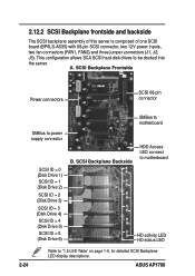
A. SCSI Backplane Frontside Power connectors SCSI 68-pin connector SMBus to motherboard SMBus to "1.5 LED Table" on page 1-6, for detailed SCSI Backplane LED display descriptions. SCSI Backplane Backside HDD Access LED connect to motherboard HD activity LED HD status LED 2-24 Refer to power supply connector SCSI ID = 0 (Disk Drive 1) SCSI ID = 1 (Disk Drive 2) SCSI ID... fan connectors (FAN1, FAN2) and three jumper connectors (J1, J2, J3). This configuration allows SCA SCSI hard disk drives to be docked into the server. ASUS AP1700
A. SCSI Backplane Frontside Power connectors SCSI 68-pin connector SMBus to motherboard SMBus to "1.5 LED Table" on page 1-6, for detailed SCSI Backplane LED display descriptions. SCSI Backplane Backside HDD Access LED connect to motherboard HD activity LED HD status LED 2-24 Refer to power supply connector SCSI ID = 0 (Disk Drive 1) SCSI ID = 1 (Disk Drive 2) SCSI ID... fan connectors (FAN1, FAN2) and three jumper connectors (J1, J2, J3). This configuration allows SCA SCSI hard disk drives to be docked into the server. ASUS AP1700
User Manual
Page 52
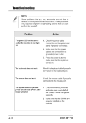
...the power button to the keyboard port. Make sure that the power cables are connected to defects on the system or the components. A-10 ASUS AP1700 These problems only requires simple troubleshooting actions that the system is turned on 1. Check the power cable connection on the server and/or the ...monitor do not light up 1. Problem Action The power LED on the system rear panel if properly connected. 2. The system does not perform power-on self tests (POST) after it was turned on ....
...the power button to the keyboard port. Make sure that the power cables are connected to defects on the system or the components. A-10 ASUS AP1700 These problems only requires simple troubleshooting actions that the system is turned on 1. Check the power cable connection on the server and/or the ...monitor do not light up 1. Problem Action The power LED on the system rear panel if properly connected. 2. The system does not perform power-on self tests (POST) after it was turned on ....