User Manual
Page 4
... guarantee that may cause undesired operation. The use of shielded cables for connection of the monitor to the graphics card is subject to Part 15 of Communications. iv ASUS AP1700 Operation is required to assure compliance with the limits for radio noise emissions from that to which can radiate radio frequency energy and, if not installed and used in the Radio Interference Regulations...
... guarantee that may cause undesired operation. The use of shielded cables for connection of the monitor to the graphics card is subject to Part 15 of Communications. iv ASUS AP1700 Operation is required to assure compliance with the limits for radio noise emissions from that to which can radiate radio frequency energy and, if not installed and used in the Radio Interference Regulations...
User Manual
Page 5
... Safety vii Operation Safety vii Introduction About this guide I-1 Audience I-2 Contents I-2 Conventions I-3 References I-3 System Package Contents I-4 Chapter 1: System Overview System Overview 1-1 1.1 System Features 1-2 1.2 Front Panel Features 1-3 1.3 Rear Panel Features 1-4 1.4 Internal Features 1-5 1.5 LED Table 1-6 Chapter 2: Hardware Reference Hardware Reference 2-1 2.1 Removing and installing chassis cover 2-2 2.2 Motherboard Placement 2-4 2.3 Central Processing Unit 2-5 2.4 System Memory 2-9 2.5 Fixed Device Bays 2-12 2.6 Hard Disk Drives 2-16 User's Manual v
... Safety vii Operation Safety vii Introduction About this guide I-1 Audience I-2 Contents I-2 Conventions I-3 References I-3 System Package Contents I-4 Chapter 1: System Overview System Overview 1-1 1.1 System Features 1-2 1.2 Front Panel Features 1-3 1.3 Rear Panel Features 1-4 1.4 Internal Features 1-5 1.5 LED Table 1-6 Chapter 2: Hardware Reference Hardware Reference 2-1 2.1 Removing and installing chassis cover 2-2 2.2 Motherboard Placement 2-4 2.3 Central Processing Unit 2-5 2.4 System Memory 2-9 2.5 Fixed Device Bays 2-12 2.6 Hard Disk Drives 2-16 User's Manual v
User Manual
Page 6
2.7 Screwless Expansion Card Slot 2-18 2.8 Long Card Support Guide 2-19 2.9 Hard Drive Blower 2-20 2.10 Chassis Fan 2-21 2.11 Connecting Cables 2-22 2.12 SCSI Backplane 2-23 Appendix A: Optional chassis roller-wheel Chassis Roller-wheel Installation A-2 Appendix B: Power Modules Redundant Power Modules A-4 Appendix C: Troubleshooting Troubleshooting A-9 vi ASUS AP1700
2.7 Screwless Expansion Card Slot 2-18 2.8 Long Card Support Guide 2-19 2.9 Hard Drive Blower 2-20 2.10 Chassis Fan 2-21 2.11 Connecting Cables 2-22 2.12 SCSI Backplane 2-23 Appendix A: Optional chassis roller-wheel Chassis Roller-wheel Installation A-2 Appendix B: Power Modules Redundant Power Modules A-4 Appendix C: Troubleshooting Troubleshooting A-9 vi ASUS AP1700
User Manual
Page 7
... the power cables for the system unit and all power cables from the existing system before you add a device. • If the power supply is broken, do not try to fix it by certified or experienced engineers. • Before operating the server, carefully read all the manuals included with the server package. • Before using the server, make sure all cables are correctly connected and the power cables...
... the power cables for the system unit and all power cables from the existing system before you add a device. • If the power supply is broken, do not try to fix it by certified or experienced engineers. • Before operating the server, carefully read all the manuals included with the server package. • Before using the server, make sure all cables are correctly connected and the power cables...
User Manual
Page 10
I-2 ASUS AP1700 It includes the target audience, chapter description, and conventions used. Appendix B: Redundant Power Modules This appendix contains detailed hardware operation and specifications of the problems and offers solutions. Appendix C: Troubleshooting This appendix lists the common problems that you have to perform when installing system components. 4. It lists the possible causes of the AP1700 redundant power modules. 6. It also lists other sources of configuring an entry-level server. Chapter 1: System...
I-2 ASUS AP1700 It includes the target audience, chapter description, and conventions used. Appendix B: Redundant Power Modules This appendix contains detailed hardware operation and specifications of the problems and offers solutions. Appendix C: Troubleshooting This appendix lists the common problems that you have to perform when installing system components. 4. It lists the possible causes of the AP1700 redundant power modules. 6. It also lists other sources of configuring an entry-level server. Chapter 1: System...

User Manual
Page 12
... Tower/5U Rackmount chassis 2) ASUS PR-DLS motherboard 3) 500W+500W redundant power supply 4) Backplane board (BP6LS-AS35) 5) CD-ROM drive (1 piece) 6) floppy disk drive (1 piece) 7) special heatsink with fan assembly (2 sets) 8) hot swap SCSI hard disk drive tray (6 units) 9) AC power cord (2 pieces) 10) Support CD that includes drivers, utilities, ASUS System Monitoring Agent (ASMA) with the ASUS Server Web-based Management (ASWM) 11) Motherboard user guide 12) System user guide 13) chassis roller wheels (4 sets) Optional: 1) ASUS AS-35 5U rackmount rail kit If any of...
... Tower/5U Rackmount chassis 2) ASUS PR-DLS motherboard 3) 500W+500W redundant power supply 4) Backplane board (BP6LS-AS35) 5) CD-ROM drive (1 piece) 6) floppy disk drive (1 piece) 7) special heatsink with fan assembly (2 sets) 8) hot swap SCSI hard disk drive tray (6 units) 9) AC power cord (2 pieces) 10) Support CD that includes drivers, utilities, ASUS System Monitoring Agent (ASMA) with the ASUS Server Web-based Management (ASWM) 11) Motherboard user guide 12) System user guide 13) chassis roller wheels (4 sets) Optional: 1) ASUS AS-35 5U rackmount rail kit If any of...
User Manual
Page 14
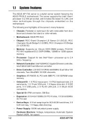
... registered ECC DDR DIMMs, 128MB to 12GB system memory. • Processor: Support for SCA SCSI hard drives, 3 X 5.25 inch bay, 1 X floppy disk drive bay. • Power Supply: 500W redundant power supply. • Hardware Monitors: Voltage, temperature, Automatic System Restart (ASR), fan speed. 1-2 ASUS AP1700 1.1 System Features The ASUS AP1700 server is a stylish server system featuring the ASUS PR-DLS motherboard. Two UltraDMA 100 IDE channels. • Graphics: ATI RAGE-XL PCI with removable front door bezel and chassis foot stand...
... registered ECC DDR DIMMs, 128MB to 12GB system memory. • Processor: Support for SCA SCSI hard drives, 3 X 5.25 inch bay, 1 X floppy disk drive bay. • Power Supply: 500W redundant power supply. • Hardware Monitors: Voltage, temperature, Automatic System Restart (ASR), fan speed. 1-2 ASUS AP1700 1.1 System Features The ASUS AP1700 server is a stylish server system featuring the ASUS PR-DLS motherboard. Two UltraDMA 100 IDE channels. • Graphics: ATI RAGE-XL PCI with removable front door bezel and chassis foot stand...
User Manual
Page 15
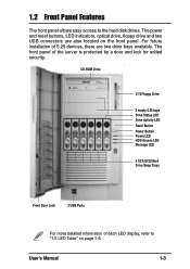
.... User's Manual 1-3 CD-ROM Drive 31/2 Floppy Drive 2 empty 5.25 bays Drive Status LED Drive Activity LED Reset Button Power Button Power LED HDD Access LED Message LED 6 SCA SCSI Hard Drive Swap Trays Front Door Lock 2 USB Ports For more detailed information of each LED display, refer to the hard disk drives. 1.2 Front Panel Features The front panel allows easy access to "1.5 LED Table" on the front panel. The front panel of 5.25 devices, there are also located on page 1-6. The power and reset buttons, LED indicators, optical drive, floppy drive and two USB connectors...
.... User's Manual 1-3 CD-ROM Drive 31/2 Floppy Drive 2 empty 5.25 bays Drive Status LED Drive Activity LED Reset Button Power Button Power LED HDD Access LED Message LED 6 SCA SCSI Hard Drive Swap Trays Front Door Lock 2 USB Ports For more detailed information of each LED display, refer to the hard disk drives. 1.2 Front Panel Features The front panel allows easy access to "1.5 LED Table" on the front panel. The front panel of 5.25 devices, there are also located on page 1-6. The power and reset buttons, LED indicators, optical drive, floppy drive and two USB connectors...
User Manual
Page 17
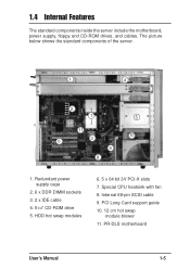
Special CPU heatsink with fan 8. HDD hot swap modules 6. 5 x 64 bit 3V PCI-X slots 7. The picture below shows the standard components of the server. 1 4 2 7 5 11 6 3 10 9 8 1. Internal 68-pin SCSI cable 9. 1.4 Internal Features The standard components inside the server include the motherboard, power supply, floppy and CD-ROM drives, and cables. PR-DLS motherboard User's Manual 1-5 PCI Long Card support guide 10. 12 cm hot swap module blower 11. Redundant power supply cage 2. 6 x DDR DIMM sockets 3. 2 x IDE cable 4. 51/4" CD-ROM drive 5.
Special CPU heatsink with fan 8. HDD hot swap modules 6. 5 x 64 bit 3V PCI-X slots 7. The picture below shows the standard components of the server. 1 4 2 7 5 11 6 3 10 9 8 1. Internal 68-pin SCSI cable 9. 1.4 Internal Features The standard components inside the server include the motherboard, power supply, floppy and CD-ROM drives, and cables. PR-DLS motherboard User's Manual 1-5 PCI Long Card support guide 10. 12 cm hot swap module blower 11. Redundant power supply cage 2. 6 x DDR DIMM sockets 3. 2 x IDE cable 4. 51/4" CD-ROM drive 5.
User Manual
Page 18
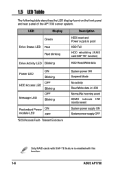
... front panel and rear panel of the AP1700 server system. LED Display Description Green Drive Status LED Red Red blinking HDD insert and Power supply is enabled with SAF-TE feature is good HDD Fail HDD rebuilding (RAID card SAF-TE* function) Drive Activity LED Blinking HDD Read/Write data Power LED ON Blinking OFF HDD Access LED Blinking Message LED OFF Blinking Redundant Power ON module LED OFF *SCSI Access Fault - Tolerant Enclosure System power ON Suspend Mode No activity Read/Write data in HDD Normal/No incoming event...
... front panel and rear panel of the AP1700 server system. LED Display Description Green Drive Status LED Red Red blinking HDD insert and Power supply is enabled with SAF-TE feature is good HDD Fail HDD rebuilding (RAID card SAF-TE* function) Drive Activity LED Blinking HDD Read/Write data Power LED ON Blinking OFF HDD Access LED Blinking Message LED OFF Blinking Redundant Power ON module LED OFF *SCSI Access Fault - Tolerant Enclosure System power ON Suspend Mode No activity Read/Write data in HDD Normal/No incoming event...
User Manual
Page 20
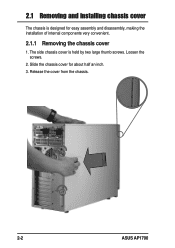
Release the cover from the chassis. 2-2 ASUS AP1700 Slide the chassis cover for easy assembly and disassembly, making the installation of internal components very convenient. 2.1.1 Removing the chassis cover 1. The side chassis cover is designed for about half an inch. 3. Loosen the screws. 2. 2.1 Removing and installing chassis cover The chassis is held by two large thumb screws.
Release the cover from the chassis. 2-2 ASUS AP1700 Slide the chassis cover for easy assembly and disassembly, making the installation of internal components very convenient. 2.1.1 Removing the chassis cover 1. The side chassis cover is designed for about half an inch. 3. Loosen the screws. 2. 2.1 Removing and installing chassis cover The chassis is held by two large thumb screws.
User Manual
Page 25
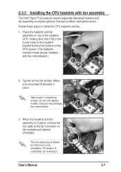
... properly in place, connect the fan cable to the fan connector on top of the CPU socket. (The heatsink bracket comes factory installed with fan assembly The Intel® Xeon™ processors require especially designed heatsink and fan assembly to install the CPU heatsink and fan. 1. Do not over-tighten screws, doing so may damage the motherboard! 3. The fan cable plug is in place. User's Manual 2-7 If it doesn...
... properly in place, connect the fan cable to the fan connector on top of the CPU socket. (The heatsink bracket comes factory installed with fan assembly The Intel® Xeon™ processors require especially designed heatsink and fan assembly to install the CPU heatsink and fan. 1. Do not over-tighten screws, doing so may damage the motherboard! 3. The fan cable plug is in place. User's Manual 2-7 If it doesn...
User Manual
Page 28
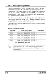
... other socket would not work. The following table lists the DIMM socket pairs and the memory modules that you can install. As a rule, this configuration requires that you install identical DDR DIMMs (exactly the same type and size) in a two-way interleaved configuration. 2.4.2 Memory Configurations The motherboard supports system memory of 512MB module into DDRA2. The same rule applies to use only the specified DIMM types for stable system operation. 2-10 ASUS AP1700
... other socket would not work. The following table lists the DIMM socket pairs and the memory modules that you can install. As a rule, this configuration requires that you install identical DDR DIMMs (exactly the same type and size) in a two-way interleaved configuration. 2.4.2 Memory Configurations The motherboard supports system memory of 512MB module into DDRA2. The same rule applies to use only the specified DIMM types for stable system operation. 2-10 ASUS AP1700
User Manual
Page 31
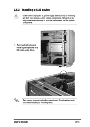
Remove the front panel cover by using thumb or a flat head screw driver. Take caution in removing the front panel cover. 2.5.2 Installing a 5.25 device Make sure to both the motherboard and the system components. 1. Do not use too much force when installing or removing items. User's Manual 2-13 Failure to do so may cause severe damage to unplug the AC power supply before adding or removing any 5.25 fixed device or other system components.
Remove the front panel cover by using thumb or a flat head screw driver. Take caution in removing the front panel cover. 2.5.2 Installing a 5.25 device Make sure to both the motherboard and the system components. 1. Do not use too much force when installing or removing items. User's Manual 2-13 Failure to do so may cause severe damage to unplug the AC power supply before adding or removing any 5.25 fixed device or other system components.
User Manual
Page 37
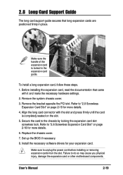
... the expansion card guide. Secure the card to unplug the power cord before installing or removing expansion cards from the slot. Install the necessary software drivers for more details. 6. Set up the BIOS if necessary. 8. 2.8 Long Card Support Guide The long card support guide secures that came with the slot and press firmly until the card is locked in place. Remove the system chassis cover. 3. Align the long card connector with it and make the necessary hardware settings. 2. Replace the chassis cover. 7. Make...
... the expansion card guide. Secure the card to unplug the power cord before installing or removing expansion cards from the slot. Install the necessary software drivers for more details. 6. Set up the BIOS if necessary. 8. 2.8 Long Card Support Guide The long card support guide secures that came with the slot and press firmly until the card is locked in place. Remove the system chassis cover. 3. Align the long card connector with it and make the necessary hardware settings. 2. Replace the chassis cover. 7. Make...
User Manual
Page 39
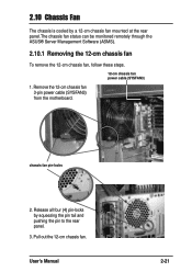
Release all four (4) pin-locks by a 12-cm chassis fan mounted at the rear panel.The chassis fan status can be monitored remotely through the ASUS® Server Management Software (ASMS). 2.10.1 Removing the 12-cm chassis fan To remove the 12-cm chassis fan, follow these steps. 12-cm chassis fan power cable (SYSFAN3) 1. Pull out the 12-cm chassis fan. Remove the 12-cm chassis fan 3-pin power cable (SYSFAN3) from the motherboard. User's Manual 2-21 2.10 Chassis Fan The chassis is cooled by squeezing the pin tail and pushing the pin to the rear panel. 3. chassis fan pin-locks 2.
Release all four (4) pin-locks by a 12-cm chassis fan mounted at the rear panel.The chassis fan status can be monitored remotely through the ASUS® Server Management Software (ASMS). 2.10.1 Removing the 12-cm chassis fan To remove the 12-cm chassis fan, follow these steps. 12-cm chassis fan power cable (SYSFAN3) 1. Pull out the 12-cm chassis fan. Remove the 12-cm chassis fan 3-pin power cable (SYSFAN3) from the motherboard. User's Manual 2-21 2.10 Chassis Fan The chassis is cooled by squeezing the pin tail and pushing the pin to the rear panel. 3. chassis fan pin-locks 2.
User Manual
Page 40
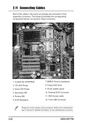
... connectors. 12 3 5 4 6 7 89 1. External SCSI Connector 11. Secondary IDE 5. The following illustrates the corresponding components that are already pre-connected to backplane 8. SCSI Backplane 12 10 11 7.SMBUS Panel to their respective connectors. Front USB Connector These are not the names of the cables in the server are connected to the motherboard user's manual for detailed information on the motherboard connectors. 2-22 ASUS AP1700 HDD Access cable 12. 2.11 Connecting Cables Most of the connectors. Floppy Disk Drive...
... connectors. 12 3 5 4 6 7 89 1. External SCSI Connector 11. Secondary IDE 5. The following illustrates the corresponding components that are already pre-connected to backplane 8. SCSI Backplane 12 10 11 7.SMBUS Panel to their respective connectors. Front USB Connector These are not the names of the cables in the server are connected to the motherboard user's manual for detailed information on the motherboard connectors. 2-22 ASUS AP1700 HDD Access cable 12. 2.11 Connecting Cables Most of the connectors. Floppy Disk Drive...
User Manual
Page 42
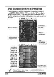
... into the server. This configuration allows SCA SCSI hard disk drives to power supply connector SCSI ID = 0 (Disk Drive 1) SCSI ID = 1 (Disk Drive 2) SCSI ID = 2 (Disk Drive 3) SCSI ID = 3 (Disk Drive 4) SCSI ID = 4 (Disk Drive 5) SCSI ID = 5 (Disk Drive 6) B. ASUS AP1700 A. 2.12.2 SCSI Backplane frontside and backside The SCSI backplane assembly of this server is comprised of one SCSI board (BP6LS-AS35) with 68-pin SCSI connector, two 12V power inputs, two fan connectors (FAN1, FAN2) and three jumper connectors (J1, J2, J3). SCSI Backplane Backside HDD Access LED connect to...
... into the server. This configuration allows SCA SCSI hard disk drives to power supply connector SCSI ID = 0 (Disk Drive 1) SCSI ID = 1 (Disk Drive 2) SCSI ID = 2 (Disk Drive 3) SCSI ID = 3 (Disk Drive 4) SCSI ID = 4 (Disk Drive 5) SCSI ID = 5 (Disk Drive 6) B. ASUS AP1700 A. 2.12.2 SCSI Backplane frontside and backside The SCSI backplane assembly of this server is comprised of one SCSI board (BP6LS-AS35) with 68-pin SCSI connector, two 12V power inputs, two fan connectors (FAN1, FAN2) and three jumper connectors (J1, J2, J3). SCSI Backplane Backside HDD Access LED connect to...
User Manual
Page 48
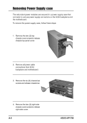
Remove the two (2) top chassis cover screws to release right-side cover. Remove the six (6) chassis bar screws and release chassis bar. 4. To remove the power supply case, follow these steps: 1. Remove the two (2) right-side chassis cover screws to release chassis top panel cover. 2. Remove all power cable connections from SCSI backplane and motherboard. 3. Removing Power Supply case The redundant power modules are secured in a power supply case that connects to various power supply connectors on the SCSI backplane and the motherboard. A-6 ASUS AP1700
Remove the two (2) top chassis cover screws to release right-side cover. Remove the six (6) chassis bar screws and release chassis bar. 4. To remove the power supply case, follow these steps: 1. Remove the two (2) right-side chassis cover screws to release chassis top panel cover. 2. Remove all power cable connections from SCSI backplane and motherboard. 3. Removing Power Supply case The redundant power modules are secured in a power supply case that connects to various power supply connectors on the SCSI backplane and the motherboard. A-6 ASUS AP1700
User Manual
Page 53
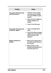
... was turned on the rear panel. 2. The message "Non-system disk or disk error" appears 1. Make sure that the DIMMs are properly installed and connected to the RJ-45 port on 1. Check the memory modules and make sure you have installed the network drivers from the system support CD. Check if the HDDs are properly installed on the backplane. Make sure the network cable is active. 2. User's Manual A-11 Network connection not available 1. Problem Action The system continuously beeps...
... was turned on the rear panel. 2. The message "Non-system disk or disk error" appears 1. Make sure that the DIMMs are properly installed and connected to the RJ-45 port on 1. Check the memory modules and make sure you have installed the network drivers from the system support CD. Check if the HDDs are properly installed on the backplane. Make sure the network cable is active. 2. User's Manual A-11 Network connection not available 1. Problem Action The system continuously beeps...


