User Guide
Page 4
... items 3-2 3.2 Rack rails assembly 3-2 3.3 Attaching the rails to the rack 3-3 3.4 Rackmounting the server 3-4 Chapter 4: Motherboard information 4-1 4.1 Motherboard layout 4-2 4.2 Jumpers 4-5 4.3 Connectors 4-10 Chapter 5: BIOS SETUP 5-1 5.1 Managing and updating your BIOS 5-2 5.1.1 Creating a bootable floppy disk 5-2 5.1.2 AFUDOS Utility 5-3 5.1.3 ASUS CrashFree BIOS 2 utility 5-6 5.1.4 ASUS Update utility 5-8 5.2 BIOS setup program 5-11 5.2.1 BIOS menu screen 5-12 5.2.2 Menu bar 5-12 5.2.3 Navigation...
... items 3-2 3.2 Rack rails assembly 3-2 3.3 Attaching the rails to the rack 3-3 3.4 Rackmounting the server 3-4 Chapter 4: Motherboard information 4-1 4.1 Motherboard layout 4-2 4.2 Jumpers 4-5 4.3 Connectors 4-10 Chapter 5: BIOS SETUP 5-1 5.1 Managing and updating your BIOS 5-2 5.1.1 Creating a bootable floppy disk 5-2 5.1.2 AFUDOS Utility 5-3 5.1.3 ASUS CrashFree BIOS 2 utility 5-6 5.1.4 ASUS Update utility 5-8 5.2 BIOS setup program 5-11 5.2.1 BIOS menu screen 5-12 5.2.2 Menu bar 5-12 5.2.3 Navigation...
User Guide
Page 8
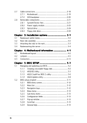
..., and experienced users with the server. Contents This guide contains the following parts: 1. Chapter 4: Motherboard information This chapter gives information about the motherboard that you have to perform when installing or removing system components. 3. This chapter includes the motherboard layout, jumper settings, and connector locations. 5. Chapter 1: Product Introduction This chapter describes the general...
..., and experienced users with the server. Contents This guide contains the following parts: 1. Chapter 4: Motherboard information This chapter gives information about the motherboard that you have to perform when installing or removing system components. 3. This chapter includes the motherboard layout, jumper settings, and connector locations. 5. Chapter 1: Product Introduction This chapter describes the general...
User Guide
Page 9
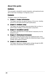
... aid in completing a task. ix C A U T I O N : Information to prevent damage to the components when trying to the ASUS contact information. ASUS NCL-DS1R1 motherboard user guide This manual contains detailed information about the ASUS NCL-DS1R1 motherboard. 2 . Refer to complete a task. ASUS Server Web-based Management (ASWM) user guide This manual tells how to complete a task. W A R N I M P O R T A N T : Instructions...
... aid in completing a task. ix C A U T I O N : Information to prevent damage to the components when trying to the ASUS contact information. ASUS NCL-DS1R1 motherboard user guide This manual contains detailed information about the ASUS NCL-DS1R1 motherboard. 2 . Refer to complete a task. ASUS Server Web-based Management (ASWM) user guide This manual tells how to complete a task. W A R N I M P O R T A N T : Instructions...
User Guide
Page 12
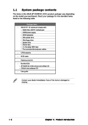
... package for the standard items listed in the ASUS AP1600R-E2 (CS3) product package vary depending on the model your dealer immediately if any of the items is damaged or missing. 1-2 Chapter 1: Product introduction Package items ASUS R11 1U rackmount chassis with: • ASUS NCL-DS1R1 motherboard • 500W power supply • SCSI backplane •...
... package for the standard items listed in the ASUS AP1600R-E2 (CS3) product package vary depending on the model your dealer immediately if any of the items is damaged or missing. 1-2 Chapter 1: Product introduction Package items ASUS R11 1U rackmount chassis with: • ASUS NCL-DS1R1 motherboard • 500W power supply • SCSI backplane •...
User Guide
Page 13
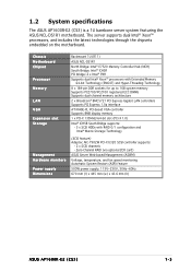
... Technology (SCSI feature) Adaptec AIC-7902W PCI-X U320 SCSI controller supports: - 2 x SCSI channels - 1.2 System specifications The ASUS AP1600R-E2 (CS3) is a 1U barebone server system featuring the ASUS NCL-DS1R1 motherboard. Zero-Channel RAID (via optional ZCR card) ASUS Server Web-based Management (ASWM) Voltage, temperature, and fan speed monitoring Automatic System Restart (ASR) feature...
... Technology (SCSI feature) Adaptec AIC-7902W PCI-X U320 SCSI controller supports: - 2 x SCSI channels - 1.2 System specifications The ASUS AP1600R-E2 (CS3) is a 1U barebone server system featuring the ASUS NCL-DS1R1 motherboard. Zero-Channel RAID (via optional ZCR card) ASUS Server Web-based Management (ASWM) Voltage, temperature, and fan speed monitoring Automatic System Restart (ASR) feature...
User Guide
Page 15
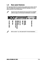
1-5 1.4 Rear panel features The rear panel includes the expansion slot, system power socket, and rear fans. Expansion slot LAN port1 LAN port2 VGA port Serial port USB ports PS/2 keyboard port PS/2 mouse port Rear fans AC power socket ASUS AP1600R-E2 (CS3) The middle part includes the I/O shield with openings for the PS/2 keyboard, PS/2 mouse, USB, VGA, and Gigabit LAN do not appear on the motherboard. The ports for the rear panel connectors on the rear panel if motherboard is not present. Refer to section "1.6.2 Rear panel LEDs" for the LED descriptions.
1-5 1.4 Rear panel features The rear panel includes the expansion slot, system power socket, and rear fans. Expansion slot LAN port1 LAN port2 VGA port Serial port USB ports PS/2 keyboard port PS/2 mouse port Rear fans AC power socket ASUS AP1600R-E2 (CS3) The middle part includes the I/O shield with openings for the PS/2 keyboard, PS/2 mouse, USB, VGA, and Gigabit LAN do not appear on the motherboard. The ports for the rear panel connectors on the rear panel if motherboard is not present. Refer to section "1.6.2 Rear panel LEDs" for the LED descriptions.
User Guide
Page 16
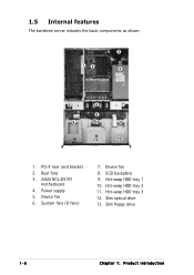
ASUS NCL-DS1R1 motherboard 4. SCSI backplane 9. Hot-swap HDD tray 3 12. Device fan 6. Slim optical drive 13. 1.5 Internal features The barebone server includes the basic components as shown. 2 13 4 5 6 7 8 9 10 11 12 13 1. Power supply 5. Hot-swap HDD tray 1 10. Hot-swap HDD tray 2 11. PCI-X riser card bracket 2. Device fan 8. Slim floppy drive 1-6 Chapter 1: Product introduction Rear fans 3. System fans (8 fans) 7.
ASUS NCL-DS1R1 motherboard 4. SCSI backplane 9. Hot-swap HDD tray 3 12. Device fan 6. Slim optical drive 13. 1.5 Internal features The barebone server includes the basic components as shown. 2 13 4 5 6 7 8 9 10 11 12 13 1. Power supply 5. Hot-swap HDD tray 1 10. Hot-swap HDD tray 2 11. PCI-X riser card bracket 2. Device fan 8. Slim floppy drive 1-6 Chapter 1: Product introduction Rear fans 3. System fans (8 fans) 7.
User Guide
Page 22
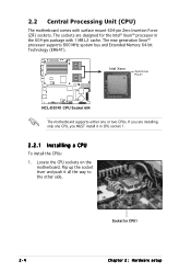
...The sockets are installing only one or two CPUs. Intel Xeon Gold Arrow Pin A1 ® NCL-DS1R1 NCL-DS1R1 CPU Socket 604 The motherboard supports either one CPU, you MUST install it all the way to the other side. Socket for the Intel® Xeon™ processor ... 604-pin package with surface mount 604-pin Zero Insertion Force (ZIF) sockets. 2.2 Central Processing Unit (CPU) The motherboard comes with 1 MB L2 cache. Locate the CPU sockets on the motherboard. The new generation Xeon™ processor supports 800 MHz system bus and Extended Memory 64-bit Technology (EM64T).
...The sockets are installing only one or two CPUs. Intel Xeon Gold Arrow Pin A1 ® NCL-DS1R1 NCL-DS1R1 CPU Socket 604 The motherboard supports either one CPU, you MUST install it all the way to the other side. Socket for the Intel® Xeon™ processor ... 604-pin package with surface mount 604-pin Zero Insertion Force (ZIF) sockets. 2.2 Central Processing Unit (CPU) The motherboard comes with 1 MB L2 cache. Locate the CPU sockets on the motherboard. The new generation Xeon™ processor supports 800 MHz system bus and Extended Memory 64-bit Technology (EM64T).
User Guide
Page 24
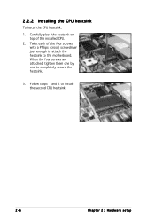
2.2.2 Installing the CPU heatsink To install the CPU heatsink: 1. When the four screws are attached, tighten them one by one to install the second CPU heatsink. 2-6 Chapter 2: Hardware setup Twist each of the installed CPU. 2. Follow steps 1 and 2 to completely secure the heatsink. 3. Carefully place the heatsink on top of the four screws with a Philips (cross) screwdriver just enough to attach the heatsink to the motherboard.
2.2.2 Installing the CPU heatsink To install the CPU heatsink: 1. When the four screws are attached, tighten them one by one to install the second CPU heatsink. 2-6 Chapter 2: Hardware setup Twist each of the installed CPU. 2. Follow steps 1 and 2 to completely secure the heatsink. 3. Carefully place the heatsink on top of the four screws with a Philips (cross) screwdriver just enough to attach the heatsink to the motherboard.
User Guide
Page 25
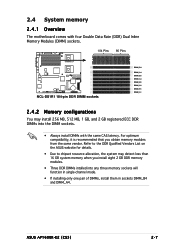
2.4 System memory 2.4.1 Overview The motherboard comes with four Double Data Rate (DDR) Dual Inline Memory Modules (DIMM) sockets. 104 Pins 80 Pins NCL-DS1R1 184-pin DDR DIMM sockets ® ... 2.4.2 Memory configurations You may detect less than 16 GB system memory when you obtain memory modules from the same vendor. ASUS AP1600R-E2 (CS3) 2-7 Refer to the DDR Qualified Vendors List on the ASUS website for details. • Due to chipset resource allocation, the system may install 256 MB, 512 MB, 1 GB, and...
2.4 System memory 2.4.1 Overview The motherboard comes with four Double Data Rate (DDR) Dual Inline Memory Modules (DIMM) sockets. 104 Pins 80 Pins NCL-DS1R1 184-pin DDR DIMM sockets ® ... 2.4.2 Memory configurations You may detect less than 16 GB system memory when you obtain memory modules from the same vendor. ASUS AP1600R-E2 (CS3) 2-7 Refer to the DDR Qualified Vendors List on the ASUS website for details. • Due to chipset resource allocation, the system may install 256 MB, 512 MB, 1 GB, and...
User Guide
Page 26
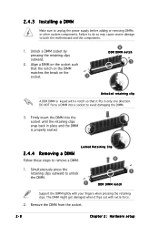
... the DIMM matches the break on the socket such that it flips out with extra force. 2. Firmly insert the DIMM into a socket to both the motherboard and the components. 1. The DIMM might get damaged when it fits in place and the DIMM is keyed with your fingers when pressing the retaining...
... the DIMM matches the break on the socket such that it flips out with extra force. 2. Firmly insert the DIMM into a socket to both the motherboard and the components. 1. The DIMM might get damaged when it fits in place and the DIMM is keyed with your fingers when pressing the retaining...
User Guide
Page 29
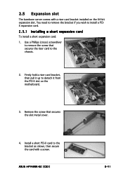
... bracket as shown, then secure the card with a riser card bracket installed on the motherboard. 3. 2.5 Expansion slot The barebone server comes with a screw. Use a Phillips (cross) screwdriver to remove the screw that secures the slot metal cover. 4. ASUS AP1600R-E2 (CS3) 2-11 Remove the screw that secures the riser card to install a PCIX...
... bracket as shown, then secure the card with a riser card bracket installed on the motherboard. 3. 2.5 Expansion slot The barebone server comes with a screw. Use a Phillips (cross) screwdriver to remove the screw that secures the slot metal cover. 4. ASUS AP1600R-E2 (CS3) 2-11 Remove the screw that secures the riser card to install a PCIX...
User Guide
Page 30
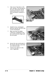
Peg on the riser card bay. Connect the cable(s) to ensure that the bracket is properly in place. Install the riser card bracket with the rear panel. 8. Secure the riser card bracket to the chassis with the screw that the golden connectors completely fit the slot and the bracket aligns with the card into the PCI-X slot on the riser card bracket should match these holes to the card, if applicable. 2-12 Chapter 2: Hardware setup Make sure that you removed earlier. 9. The two pegs on the motherboard. 7. Take note of the holes on the riser card bracket 6. 5.
Peg on the riser card bay. Connect the cable(s) to ensure that the bracket is properly in place. Install the riser card bracket with the rear panel. 8. Secure the riser card bracket to the chassis with the screw that the golden connectors completely fit the slot and the bracket aligns with the card into the PCI-X slot on the riser card bracket should match these holes to the card, if applicable. 2-12 Chapter 2: Hardware setup Make sure that you removed earlier. 9. The two pegs on the motherboard. 7. Take note of the holes on the riser card bracket 6. 5.
User Guide
Page 31
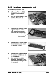
... card." 2. Install the riser card bracket with the rear panel. Card extension 4. Press the end of the plastic long card lock, then pull it up. 3. ASUS AP1600R-E2 (CS3) 2-13 Make sure that the golden connectors completely fit the slot and the bracket aligns with the card into the PCI-X slot on...
... card." 2. Install the riser card bracket with the rear panel. Card extension 4. Press the end of the plastic long card lock, then pull it up. 3. ASUS AP1600R-E2 (CS3) 2-13 Make sure that the golden connectors completely fit the slot and the bracket aligns with the card into the PCI-X slot on...
User Guide
Page 33
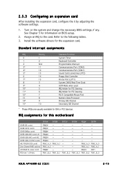
...- PIRQD# - - - - - PXH2_A_0 PXH2_A_0 PXH2_A_2 - - - PXH2_A_1 PXH2_A_1 PIRQB# - - - Turn on BIOS setup. 2. Install the software drivers for this motherboard ICH5R IDE contrl. Assign an IRQ to the following tables. 3. PIRQB# - - - - - PXH2_A_0 PXH2_A_1 - - IRQ assignments for the expansion card. ICH5R USB UHCI... for information on the system and change the necessary BIOS settings, if any. REQ1H GNT1 PXH1_B_0 PXH1_B_1 PXH1_B_2 PXH1_B_3 PXH1_B_0 PXH1_B_0 ASUS AP1600R-E2 (CS3) 2-15 PIRQC# - - - - - PIRQH# - - - - - Refer to the card. ...
...- PIRQD# - - - - - PXH2_A_0 PXH2_A_0 PXH2_A_2 - - - PXH2_A_1 PXH2_A_1 PIRQB# - - - Turn on BIOS setup. 2. Install the software drivers for this motherboard ICH5R IDE contrl. Assign an IRQ to the following tables. 3. PIRQB# - - - - - PXH2_A_0 PXH2_A_1 - - IRQ assignments for the expansion card. ICH5R USB UHCI... for information on the system and change the necessary BIOS settings, if any. REQ1H GNT1 PXH1_B_0 PXH1_B_1 PXH1_B_2 PXH1_B_3 PXH1_B_0 PXH1_B_0 ASUS AP1600R-E2 (CS3) 2-15 PIRQC# - - - - - PIRQH# - - - - - Refer to the card. ...
User Guide
Page 35
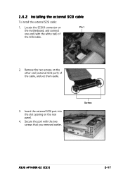
Screws ASUS AP1600R-E2 (CS3) 2-17 Insert the external SCSI port into the slot opening on the other end (external SCSI port) of the SCSI cable. 2. 2.6.2 Installing the external SCSI cable To install the external SCSI cable: 1. Locate the SCSI-B connector on Pin 1 the motherboard, and connect one end (with the two screws that you removed earlier. Secure the port with the white tab) of the cable, and set them aside. 3. Remove the two screws on the rear panel. 4.
Screws ASUS AP1600R-E2 (CS3) 2-17 Insert the external SCSI port into the slot opening on the other end (external SCSI port) of the SCSI cable. 2. 2.6.2 Installing the external SCSI cable To install the external SCSI cable: 1. Locate the SCSI-B connector on Pin 1 the motherboard, and connect one end (with the two screws that you removed earlier. Secure the port with the white tab) of the cable, and set them aside. 3. Remove the two screws on the rear panel. 4.
User Guide
Page 37
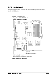
... Lithium Cell CMOS Power BUZZ1 CLRTC1 AUX_PANEL1 USB34 USBPW34 Intel PXH HDLED1 SCSI_EN1 PANEL1 Adaptec AIC-7902W 34 68 SCSIB1 1 35 SCSIA1 2-19 mPGA 604 ASUS AP1600R-E2 (CS3) USB 2.0 cable to front panel board 20-pin front panel cable to front panel board IDE cable to optical drive ® VGA 30... 604 SCSI cable to BP board LED cable to front panel board Floppy disk cable to SCSI BP board SMBus cable to SCSI BP board 2.7.1 Motherboard The following illustration describes the cables for the specific connectors on the...
... Lithium Cell CMOS Power BUZZ1 CLRTC1 AUX_PANEL1 USB34 USBPW34 Intel PXH HDLED1 SCSI_EN1 PANEL1 Adaptec AIC-7902W 34 68 SCSIB1 1 35 SCSIA1 2-19 mPGA 604 ASUS AP1600R-E2 (CS3) USB 2.0 cable to front panel board 20-pin front panel cable to front panel board IDE cable to optical drive ® VGA 30... 604 SCSI cable to BP board LED cable to front panel board Floppy disk cable to SCSI BP board SMBus cable to SCSI BP board 2.7.1 Motherboard The following illustration describes the cables for the specific connectors on the...
User Guide
Page 47
Motherboard info Chapter 4 This chapter includes the motherboard layout, and brief descriptions of the jumpers and internal connectors. ASUS AP1600R-E2 (CS3)
Motherboard info Chapter 4 This chapter includes the motherboard layout, and brief descriptions of the jumpers and internal connectors. ASUS AP1600R-E2 (CS3)
User Guide
Page 48
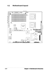
® 30.5cm (12in) NCL-DS1R1 4.1 Motherboard layout mPGA 604 COM1 KBPWR1 PS/2 T: Mouse B: Keyboard REAR_FAN2 USB1 USBPW12 USB2 33cm (13in) ATXPWR1 PSUSMB1 CPU_FAN1 DDR DIMM_B4 (64/72 bit, 184-pin module) ... CR2032 3V Lithium Cell CMOS Power BUZZ1 CLRTC1 AUX_PANEL1 USB34 USBPW34 Intel PXH HDLED1 SCSI_EN1 PANEL1 Adaptec AIC-7902W 34 68 SCSIB1 1 35 SCSIA1 4-2 Chapter 4: Motherboard information
® 30.5cm (12in) NCL-DS1R1 4.1 Motherboard layout mPGA 604 COM1 KBPWR1 PS/2 T: Mouse B: Keyboard REAR_FAN2 USB1 USBPW12 USB2 33cm (13in) ATXPWR1 PSUSMB1 CPU_FAN1 DDR DIMM_B4 (64/72 bit, 184-pin module) ... CR2032 3V Lithium Cell CMOS Power BUZZ1 CLRTC1 AUX_PANEL1 USB34 USBPW34 Intel PXH HDLED1 SCSI_EN1 PANEL1 Adaptec AIC-7902W 34 68 SCSIB1 1 35 SCSIA1 4-2 Chapter 4: Motherboard information
User Guide
Page 50
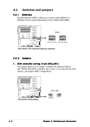
... to pins 1-2 to activate the SCSI feature, and support RAID configurations. ® NCL-DS1R1 NCL-DS1R1 SCSI setting SCSI_EN1 12 23 Enable (Default) Disable 4-4 Chapter 4: Motherboard information
... to pins 1-2 to activate the SCSI feature, and support RAID configurations. ® NCL-DS1R1 NCL-DS1R1 SCSI setting SCSI_EN1 12 23 Enable (Default) Disable 4-4 Chapter 4: Motherboard information

