

AP1400R 1U Server Manual English Edition
Page 6
IMPORTANT Motherboards, adapters, and disk drives are sensitive to avoid electrical shock. Avoid touching the solder joints or pins. • If you need to lay the device ...
IMPORTANT Motherboards, adapters, and disk drives are sensitive to avoid electrical shock. Avoid touching the solder joints or pins. • If you need to lay the device ...

AP1400R 1U Server Manual English Edition
Page 7
...Conventions 11 Symbols 11 Package Contents 12 Standard Components 12 Optional Components 12 Chapter 1: System Overview 13 Features 14 Chassis: ASUS AR-10 14 Motherboard: ASUS CUR-DLSR 14 Front Panel 15 Back Panel 15 Power Button and System LEDs 16 LED Information 16 Chapter 2: Basic... 3: Hardware Setup 19 Opening the Chassis 20 Unlocking the Cover 20 Removing the Cover 21 Internal Components 22 Motherboard Placement 23 Placement Direction 23 Motherboard Screws 23 Central Processing Unit (CPU 24 CPU Orientation 24 CPU Socket Locations 24 CPU Installation 25 CPU Heatsink...
...Conventions 11 Symbols 11 Package Contents 12 Standard Components 12 Optional Components 12 Chapter 1: System Overview 13 Features 14 Chassis: ASUS AR-10 14 Motherboard: ASUS CUR-DLSR 14 Front Panel 15 Back Panel 15 Power Button and System LEDs 16 LED Information 16 Chapter 2: Basic... 3: Hardware Setup 19 Opening the Chassis 20 Unlocking the Cover 20 Removing the Cover 21 Internal Components 22 Motherboard Placement 23 Placement Direction 23 Motherboard Screws 23 Central Processing Unit (CPU 24 CPU Orientation 24 CPU Socket Locations 24 CPU Installation 25 CPU Heatsink...
AP1400R 1U Server Manual English Edition
Page 12
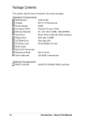
Standard Components Motherboard CUR-DLSR Chassis AR-10 1U Rackmount Power Supply 200W Processor (CPU) Pentium® III up to 1GHz Memory Modules 64, 128, 256, 512MB, 1GB ... 24X PCI Riser Card 64-bit/33MHz PCI slot SCSI Cable S370 CPU Terminator Rackmount Rails AR-10 rail kit User's Manuals CD-ROM, motherboard Optional Components RAID Controller ASUS PCI-DA2200 RAID controller 12 Introduction: About This Manual Safeguards Package Contents This section lists the items included in the server package.
Standard Components Motherboard CUR-DLSR Chassis AR-10 1U Rackmount Power Supply 200W Processor (CPU) Pentium® III up to 1GHz Memory Modules 64, 128, 256, 512MB, 1GB ... 24X PCI Riser Card 64-bit/33MHz PCI slot SCSI Cable S370 CPU Terminator Rackmount Rails AR-10 rail kit User's Manuals CD-ROM, motherboard Optional Components RAID Controller ASUS PCI-DA2200 RAID controller 12 Introduction: About This Manual Safeguards Package Contents This section lists the items included in the server package.

AP1400R 1U Server Manual English Edition
Page 14
...25-inch slim type CD-ROM drive, and three 3.5-inch wide 1-inch high hot-swappable SCA SCSI hard disk drives in removable trays Motherboard: ASUS CUR-DLSR • Processor: Dual Intel® Pentium III FC-PGA processors running up to 1GHz • Memory: Four 168-pin...8226; Integrated Super I/O: PC97317 controller that uses the ServerSetTM chipset from ServerWorks®. The motherboard supports dual Pentium III processors to accelerate even the most complicated server tasks. Checklist Features The AP1400R is configured for one 3.5-inch slim type floppy device, one PS/2 mouse • ...
...25-inch slim type CD-ROM drive, and three 3.5-inch wide 1-inch high hot-swappable SCA SCSI hard disk drives in removable trays Motherboard: ASUS CUR-DLSR • Processor: Dual Intel® Pentium III FC-PGA processors running up to 1GHz • Memory: Four 168-pin...8226; Integrated Super I/O: PC97317 controller that uses the ServerSetTM chipset from ServerWorks®. The motherboard supports dual Pentium III processors to accelerate even the most complicated server tasks. Checklist Features The AP1400R is configured for one 3.5-inch slim type floppy device, one PS/2 mouse • ...
AP1400R 1U Server Manual English Edition
Page 22
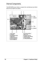
SCSI Hard Disk Bay 1 7. Slim CD-ROM Drive 4 (Top) 5 (Bottom) 6 7 (Top) 8 (Bottom) 10 9 8. Expansion Card Fan 11. Riser Card Holder 13. CPU Blower 3. Internal Components The AP1400R server interior comprise the motherboard and other parts that complete the system. 1 2 3 13 12 11 1. SCSI Backplane Board 4. Memory Fan 10. CUR-DLSR Motherboard 22 Chapter 3: Hardware Setup Floppy Drive 5. SCSI Hard Disk Bay 2 6. SCSI Hard Disk Bay 0 9. Expansion Card (optional) 12. Power Supply 2.
SCSI Hard Disk Bay 1 7. Slim CD-ROM Drive 4 (Top) 5 (Bottom) 6 7 (Top) 8 (Bottom) 10 9 8. Expansion Card Fan 11. Riser Card Holder 13. CPU Blower 3. Internal Components The AP1400R server interior comprise the motherboard and other parts that complete the system. 1 2 3 13 12 11 1. SCSI Backplane Board 4. Memory Fan 10. CUR-DLSR Motherboard 22 Chapter 3: Hardware Setup Floppy Drive 5. SCSI Hard Disk Bay 2 6. SCSI Hard Disk Bay 0 9. Expansion Card (optional) 12. Power Supply 2.

AP1400R 1U Server Manual English Edition
Page 23
... remove and re-install it into the chassis in case you place it in the future. Do not overtighten the screws. AP1400R Server User's Manual 23 Back Panel Motherboard Screws Place 11 screws in the section "Internal Components". Placement Direction When installing the... motherboard, make sure that you need to the back panel of the AP1400R server are for detailed technical information about the motherboard. The two holes marked by solid white circles are already installed as indicated in ...
... remove and re-install it into the chassis in case you place it in the future. Do not overtighten the screws. AP1400R Server User's Manual 23 Back Panel Motherboard Screws Place 11 screws in the section "Internal Components". Placement Direction When installing the... motherboard, make sure that you need to the back panel of the AP1400R server are for detailed technical information about the motherboard. The two holes marked by solid white circles are already installed as indicated in ...

AP1400R 1U Server Manual English Edition
Page 24
... to locate the sockets.) CPU Socket Locations Socket for CPU 2 Socket for CPU 1 CPU Orientation A CPU has a mark (usually a notch or a gold mark) on the motherboard. (NOTE: The CPU sockets are underneath the CPU blower tube. Safeguards Central Processing Unit (CPU) The CUR-DLSR...
... to locate the sockets.) CPU Socket Locations Socket for CPU 2 Socket for CPU 1 CPU Orientation A CPU has a mark (usually a notch or a gold mark) on the motherboard. (NOTE: The CPU sockets are underneath the CPU blower tube. Safeguards Central Processing Unit (CPU) The CUR-DLSR...

AP1400R 1U Server Manual English Edition
Page 27
Fan Connector on the motherboard. Install a CPU terminator as you would install a CPU. CPU Socket 2 with Installed Terminator CPU Socket 1 with Installed CPU and Heatsink CPU Fan Cable Connecting the Fan Cable Connect the CPU fan (blower) cable to the section "CPU Installation". Refer to the connector on the Motherboard AP1400R Server User's Manual 27 CPU T erminator When using only one processor socket, make sure to install an S370 processor terminator to the unused socket.
Fan Connector on the motherboard. Install a CPU terminator as you would install a CPU. CPU Socket 2 with Installed Terminator CPU Socket 1 with Installed CPU and Heatsink CPU Fan Cable Connecting the Fan Cable Connect the CPU fan (blower) cable to the section "CPU Installation". Refer to the connector on the Motherboard AP1400R Server User's Manual 27 CPU T erminator When using only one processor socket, make sure to install an S370 processor terminator to the unused socket.

AP1400R 1U Server Manual English Edition
Page 28
The blower has an extended tube directed to allow clearance from the motherboard components. The blower tube extends to the CPU area on the motherboard. CPU Blower and Tube Location Three screws (indicated by solid white circles. These two screws have spacers underneath to the two CPUs. Tube...maintain the ideal temperature for the CPUs, the chassis includes a 9-cm CPU blower. The blower cable connects to the CPU_FAN2 connector on the motherboard and is secured by two screws as indicated in the picture by white circles) secure the CPU blower to access the CPU and DIMM sockets...
The blower has an extended tube directed to allow clearance from the motherboard components. The blower tube extends to the CPU area on the motherboard. CPU Blower and Tube Location Three screws (indicated by solid white circles. These two screws have spacers underneath to the two CPUs. Tube...maintain the ideal temperature for the CPUs, the chassis includes a 9-cm CPU blower. The blower cable connects to the CPU_FAN2 connector on the motherboard and is secured by two screws as indicated in the picture by white circles) secure the CPU blower to access the CPU and DIMM sockets...

AP1400R 1U Server Manual English Edition
Page 29
...front panel indicates if a fan fails while another LED indicates a thermal failure. DIMM Sockets Location Locate the DIMM sockets on the motherboard. Memory Fan Expansion Card Fan Metal Bracket Connect to Connect to install memory modules. These fans maintain the ideal temperature for the system... memory and the expansion card. DIMM Sockets AP1400R Server User's Manual 29 A fan fail LED on the M/B System Memor y The motherboard has four Dual Inline Memory Module (DIMM) sockets that holds the cooling fans. Cooling Fans ...
...front panel indicates if a fan fails while another LED indicates a thermal failure. DIMM Sockets Location Locate the DIMM sockets on the motherboard. Memory Fan Expansion Card Fan Metal Bracket Connect to Connect to install memory modules. These fans maintain the ideal temperature for the system... memory and the expansion card. DIMM Sockets AP1400R Server User's Manual 29 A fan fail LED on the M/B System Memor y The motherboard has four Dual Inline Memory Module (DIMM) sockets that holds the cooling fans. Cooling Fans ...

AP1400R 1U Server Manual English Edition
Page 31
... PCI expansion slot. Expansion Card Riser Card Locking Tab PCI Slot AP1400R Server User's Manual 31 The riser card golden fingers connect to accommodate a PCI expansion card. The slot requires a PCI riser card (P64-1U) to the PCI slot on the motherboard. Insert the golden fingers of the PCI expansion card to... system package. Golden Fingers PCI Card Connector Installing an Expansion Card Carefully insert the golden fingers of the riser card to the connector on the motherboard until it fits in place.
... PCI expansion slot. Expansion Card Riser Card Locking Tab PCI Slot AP1400R Server User's Manual 31 The riser card golden fingers connect to accommodate a PCI expansion card. The slot requires a PCI riser card (P64-1U) to the PCI slot on the motherboard. Insert the golden fingers of the PCI expansion card to... system package. Golden Fingers PCI Card Connector Installing an Expansion Card Carefully insert the golden fingers of the riser card to the connector on the motherboard until it fits in place.

AP1400R 1U Server Manual English Edition
Page 34
IDE1 Connector IDE Connector on on the backplane board. SCSI Connector on the Motherboard SCSI Connector on the Backplane IDE Cable Connect one end of the cable to connector labeled IDE1 on the CD-ROM adapter board. Connect the other end to the SCSI In connector on the Motherboard the CD-ROM Adapter Board 34 Chapter 3: Hardware Setup Checklist Connecting Cables SCSI Cable Connect the 68-pin SCSI cable to the SCSI connector on the motherboard and the other end of the IDE cable to the IDE connector on the motherboard.
IDE1 Connector IDE Connector on on the backplane board. SCSI Connector on the Motherboard SCSI Connector on the Backplane IDE Cable Connect one end of the cable to connector labeled IDE1 on the CD-ROM adapter board. Connect the other end to the SCSI In connector on the Motherboard the CD-ROM Adapter Board 34 Chapter 3: Hardware Setup Checklist Connecting Cables SCSI Cable Connect the 68-pin SCSI cable to the SCSI connector on the motherboard and the other end of the IDE cable to the IDE connector on the motherboard.
AP1400R 1U Server Manual English Edition
Page 35
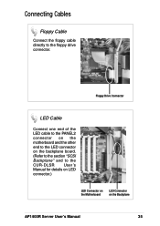
Features Connecting Cables Floppy Cable Connect the floppy cable directly to the CUR-DLSR User's Manual for details on LED connector.) LED Connector on the Motherboard LED Connector on the Backplane AP1400R Server User's Manual 35 Floppy Drive Connector LED Cable Connect one end of the LED cable to the PANEL2 connector on the motherboard and the other end to the LED connector on the backplane board. (Refer to the section "SCSI Backplane" and to the floppy drive connector.
Features Connecting Cables Floppy Cable Connect the floppy cable directly to the CUR-DLSR User's Manual for details on LED connector.) LED Connector on the Motherboard LED Connector on the Backplane AP1400R Server User's Manual 35 Floppy Drive Connector LED Cable Connect one end of the LED cable to the PANEL2 connector on the motherboard and the other end to the LED connector on the backplane board. (Refer to the section "SCSI Backplane" and to the floppy drive connector.

AP1400R 1U Server Manual English Edition
Page 36
Connecting Cables Power Cables Connect the ATX power cable to their respective connectors on the motherboard. Power Connector on the Motherboard Power Connector on the Backplane Cooling Fan Cables Connect the memory fan cable and card fan cable to the ATX power connector on the motherboard. Memory Fan Expansion Card Connector Fan Connector CHA_FAN1 CHA_FAN2 36 Chapter 3: Hardware Setup Connect the 4-pin power cable to the section "System Power Supply" for details on the backplane. Refer to the power connector on power cables.
Connecting Cables Power Cables Connect the ATX power cable to their respective connectors on the motherboard. Power Connector on the Motherboard Power Connector on the Backplane Cooling Fan Cables Connect the memory fan cable and card fan cable to the ATX power connector on the motherboard. Memory Fan Expansion Card Connector Fan Connector CHA_FAN1 CHA_FAN2 36 Chapter 3: Hardware Setup Connect the 4-pin power cable to the section "System Power Supply" for details on the backplane. Refer to the power connector on power cables.
AP1400R 1U Server Manual English Edition
Page 39
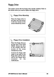
Secure the drive to the floppy drive connector on the motherboard. Connect the floppy disk cable to the back of the SCSI HDD2). Floppy Drive Installation Place the floppy drive on its bay (top of the ... the areas indicated by circles. Refer to this section when you need to the drive tray and secure it with the floppy drive already installed. AP1400R Server User's Manual 39 Floppy Drive The system comes with four screws on the areas indicated by circles. Floppy Drive Mounting Place the floppy drive...
Secure the drive to the floppy drive connector on the motherboard. Connect the floppy disk cable to the back of the SCSI HDD2). Floppy Drive Installation Place the floppy drive on its bay (top of the ... the areas indicated by circles. Refer to this section when you need to the drive tray and secure it with the floppy drive already installed. AP1400R Server User's Manual 39 Floppy Drive The system comes with four screws on the areas indicated by circles. Floppy Drive Mounting Place the floppy drive...

AP1400R 1U Server Manual English Edition
Page 41
AP1400R Server User's Manual 41 SCSI Hard Disk Drives HDD Installation After the drive is connected to the tray, carefully insert the drive into the bay, then push the levers back in place. IMPORTANT Make sure that the SCSI cable is secured to the motherboard and the backplane. Refer to the section "Connecting Cables".
AP1400R Server User's Manual 41 SCSI Hard Disk Drives HDD Installation After the drive is connected to the tray, carefully insert the drive into the bay, then push the levers back in place. IMPORTANT Make sure that the SCSI cable is secured to the motherboard and the backplane. Refer to the section "Connecting Cables".

