
AP1400R 1U Server Manual English Edition
Page 8
... Expansion Card 31 Installing an Expansion Card 31 Securing the Expansion Card 32 Securing an Extended PCI Card 32 SCSI Backplane 33 Front Side 33 Back Side 33 Connecting Cables 34 SCSI Cable 34 IDE Cable 34 Floppy Cable 35 LED Cable 35 Power Cables 36 Cooling Fan Cables 36 CD...CD-ROM Adapter Board 38 CD-ROM Installation 38 Floppy Drive 39 Floppy Drive Mounting 39 Floppy Drive Installation 39 SCSI Hard Disk Drives 40 Hot-Swap Drive Tray 40 SCSI HDD Mounting 40 HDD Installation 41 System Power Supply 42 Power Supply Specifications 43 Output Voltage Regulation 43 Output ...
... Expansion Card 31 Installing an Expansion Card 31 Securing the Expansion Card 32 Securing an Extended PCI Card 32 SCSI Backplane 33 Front Side 33 Back Side 33 Connecting Cables 34 SCSI Cable 34 IDE Cable 34 Floppy Cable 35 LED Cable 35 Power Cables 36 Cooling Fan Cables 36 CD...CD-ROM Adapter Board 38 CD-ROM Installation 38 Floppy Drive 39 Floppy Drive Mounting 39 Floppy Drive Installation 39 SCSI Hard Disk Drives 40 Hot-Swap Drive Tray 40 SCSI HDD Mounting 40 HDD Installation 41 System Power Supply 42 Power Supply Specifications 43 Output Voltage Regulation 43 Output ...
AP1400R 1U Server Manual English Edition
Page 12
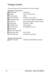
... Power Supply 200W Processor (CPU) Pentium® III up to 1GHz Memory Modules 64, 128, 256, 512MB, 1GB SDRAM Hard Drive 80-pin SCA-2 Ultra160 SCSI interface Floppy Drive Slim-type 1.44MB CD-ROM Drive Slim-type 24X PCI Riser Card 64-bit/33MHz PCI slot...
... Power Supply 200W Processor (CPU) Pentium® III up to 1GHz Memory Modules 64, 128, 256, 512MB, 1GB SDRAM Hard Drive 80-pin SCA-2 Ultra160 SCSI interface Floppy Drive Slim-type 1.44MB CD-ROM Drive Slim-type 24X PCI Riser Card 64-bit/33MHz PCI slot...

AP1400R 1U Server Manual English Edition
Page 14
...power supply equipped with 4MB PC100 SDRAM • Integrated Super I/O: PC97317 controller that uses the ServerSetTM chipset from ServerWorks®. Checklist Features The AP1400R is configured for one 3.5-inch slim type floppy device, one 5.25-inch slim type CD-ROM drive, and three 3.5-inch wide 1-inch ...fits in removable trays Motherboard: ASUS CUR-DLSR • Processor: Dual Intel® Pentium III FC-PGA processors running up to 1GHz • Memory: Four 168-pin DIMM sockets that support up to 4GB PC133 registered SDRAM with ECC support • Onboard SCSI: LSI® 53C1010-33 dual...
...power supply equipped with 4MB PC100 SDRAM • Integrated Super I/O: PC97317 controller that uses the ServerSetTM chipset from ServerWorks®. Checklist Features The AP1400R is configured for one 3.5-inch slim type floppy device, one 5.25-inch slim type CD-ROM drive, and three 3.5-inch wide 1-inch ...fits in removable trays Motherboard: ASUS CUR-DLSR • Processor: Dual Intel® Pentium III FC-PGA processors running up to 1GHz • Memory: Four 168-pin DIMM sockets that support up to 4GB PC133 registered SDRAM with ECC support • Onboard SCSI: LSI® 53C1010-33 dual...

AP1400R 1U Server Manual English Edition
Page 15
... panel (see next page for an expansion card. 1 2 3 45 6 7 8 9 10 11 1. USB Ports 1 and 2 5. High-Density SCSI Connector AP1400R Server User's Manual 15 PS/2 Keyboard Port 3. Printer Port 7. Features Front Panel The front panel of the AP1400R server allows easy access to the floppy, CD-ROM, and removable hard disk drives. PS/2 Mouse...
... panel (see next page for an expansion card. 1 2 3 45 6 7 8 9 10 11 1. USB Ports 1 and 2 5. High-Density SCSI Connector AP1400R Server User's Manual 15 PS/2 Keyboard Port 3. Printer Port 7. Features Front Panel The front panel of the AP1400R server allows easy access to the floppy, CD-ROM, and removable hard disk drives. PS/2 Mouse...
AP1400R 1U Server Manual English Edition
Page 16
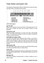
... normal, this LED is ON (steady green) under normal conditions. The LED turns to steady red. This LED is unlit when there is an IDE/SCSI HDD activity. Message LED This LED is ON (steady green). Reset Switch 2. When a hard disk is installed, the specific LED for that hard disk.... Temperature LED When the system temperature is normal, this LED is software programmable to the system by pressing the power button. SCSI HDD Drive Status LEDs The SCSI hard disks have individual LEDs. Power Button and System LEDs The chassis includes system LEDs to steady red when the fan speed ...
... normal, this LED is ON (steady green) under normal conditions. The LED turns to steady red. This LED is unlit when there is an IDE/SCSI HDD activity. Message LED This LED is ON (steady green). Reset Switch 2. When a hard disk is installed, the specific LED for that hard disk.... Temperature LED When the system temperature is normal, this LED is software programmable to the system by pressing the power button. SCSI HDD Drive Status LEDs The SCSI hard disks have individual LEDs. Power Button and System LEDs The chassis includes system LEDs to steady red when the fan speed ...
AP1400R 1U Server Manual English Edition
Page 22
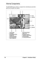
SCSI Backplane Board 4. SCSI Hard Disk Bay 2 6. Expansion Card (optional) 12. Internal Components The AP1400R server interior comprise the motherboard and other parts that complete the system. 1 2 3 13 12 11 1. Riser Card Holder 13. CUR-DLSR Motherboard 22 Chapter 3: Hardware Setup Memory Fan 10. CPU Blower 3. SCSI Hard Disk Bay 1 7. Power Supply 2. Floppy Drive 5. SCSI Hard Disk Bay 0 9. Expansion Card Fan 11. Slim CD-ROM Drive 4 (Top) 5 (Bottom) 6 7 (Top) 8 (Bottom) 10 9 8.
SCSI Backplane Board 4. SCSI Hard Disk Bay 2 6. Expansion Card (optional) 12. Internal Components The AP1400R server interior comprise the motherboard and other parts that complete the system. 1 2 3 13 12 11 1. Riser Card Holder 13. CUR-DLSR Motherboard 22 Chapter 3: Hardware Setup Memory Fan 10. CPU Blower 3. SCSI Hard Disk Bay 1 7. Power Supply 2. Floppy Drive 5. SCSI Hard Disk Bay 0 9. Expansion Card Fan 11. Slim CD-ROM Drive 4 (Top) 5 (Bottom) 6 7 (Top) 8 (Bottom) 10 9 8.
AP1400R 1U Server Manual English Edition
Page 33
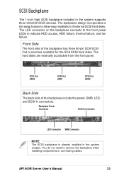
... installed in the system supports three Ultra160 SCSI devices. AP1400R Server User's Manual 33 SCSI Out HDD0 SCSI Out HDD1 SCSI Out HDD2 Back Side The back side of the backplane has three 80-pin SCA SCSI Out connectors available for the SCA SCSI hard disks. SCSI Backplane The 1-inch high SCSI backplane included in the system chassis. The...
... installed in the system supports three Ultra160 SCSI devices. AP1400R Server User's Manual 33 SCSI Out HDD0 SCSI Out HDD1 SCSI Out HDD2 Back Side The back side of the backplane has three 80-pin SCA SCSI Out connectors available for the SCA SCSI hard disks. SCSI Backplane The 1-inch high SCSI backplane included in the system chassis. The...

AP1400R 1U Server Manual English Edition
Page 34
IDE1 Connector IDE Connector on on the Motherboard the CD-ROM Adapter Board 34 Chapter 3: Hardware Setup SCSI Connector on the Motherboard SCSI Connector on the Backplane IDE Cable Connect one end of the cable to connector labeled IDE1 on the motherboard. Connect the other end to the SCSI In connector on the backplane board. Checklist Connecting Cables SCSI Cable Connect the 68-pin SCSI cable to the SCSI connector on the motherboard and the other end of the IDE cable to the IDE connector on the CD-ROM adapter board.
IDE1 Connector IDE Connector on on the Motherboard the CD-ROM Adapter Board 34 Chapter 3: Hardware Setup SCSI Connector on the Motherboard SCSI Connector on the Backplane IDE Cable Connect one end of the cable to connector labeled IDE1 on the motherboard. Connect the other end to the SCSI In connector on the backplane board. Checklist Connecting Cables SCSI Cable Connect the 68-pin SCSI cable to the SCSI connector on the motherboard and the other end of the IDE cable to the IDE connector on the CD-ROM adapter board.
AP1400R 1U Server Manual English Edition
Page 35
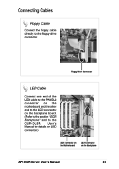
Floppy Drive Connector LED Cable Connect one end of the LED cable to the PANEL2 connector on the motherboard and the other end to the LED connector on the Backplane AP1400R Server User's Manual 35 Features Connecting Cables Floppy Cable Connect the floppy cable directly to the CUR-DLSR User's Manual for details on LED connector.) LED Connector on the Motherboard LED Connector on the backplane board. (Refer to the section "SCSI Backplane" and to the floppy drive connector.
Floppy Drive Connector LED Cable Connect one end of the LED cable to the PANEL2 connector on the motherboard and the other end to the LED connector on the Backplane AP1400R Server User's Manual 35 Features Connecting Cables Floppy Cable Connect the floppy cable directly to the CUR-DLSR User's Manual for details on LED connector.) LED Connector on the Motherboard LED Connector on the backplane board. (Refer to the section "SCSI Backplane" and to the floppy drive connector.
AP1400R 1U Server Manual English Edition
Page 37
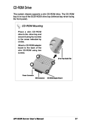
Drive Tray Guide Tab Power Connector IDE Connector CD-ROM Adapter Board AP1400R Server User's Manual 37 CD-ROM Drive The system chassis supports a slim CD-ROM drive. CD-ROM Mounting Place a slim CD-ROM drive to the back of the SCSI HDD0 drive bay (leftmost bay when facing the front panel). Attach a CD-ROM adapter board to the drive tray and secure it using two screws. The CD-ROM bay is on top of the slim CD-ROM using four screws in the areas indicated by circles.
Drive Tray Guide Tab Power Connector IDE Connector CD-ROM Adapter Board AP1400R Server User's Manual 37 CD-ROM Drive The system chassis supports a slim CD-ROM drive. CD-ROM Mounting Place a slim CD-ROM drive to the back of the SCSI HDD0 drive bay (leftmost bay when facing the front panel). Attach a CD-ROM adapter board to the drive tray and secure it using two screws. The CD-ROM bay is on top of the slim CD-ROM using four screws in the areas indicated by circles.
AP1400R 1U Server Manual English Edition
Page 39
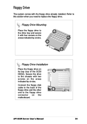
Floppy Drive Installation Place the floppy drive on its bay (top of the floppy drive and the other end to replace the floppy drive. AP1400R Server User's Manual 39 Floppy Drive The system comes with two screws on the areas indicated by circles. Secure the drive to the drive tray ...and secure it with four screws on the motherboard. Connect the floppy disk cable to the back of the SCSI HDD2). Refer to this section when you need to the floppy drive connector on the areas indicated by circles. Floppy Drive Mounting Place the floppy...
Floppy Drive Installation Place the floppy drive on its bay (top of the floppy drive and the other end to replace the floppy drive. AP1400R Server User's Manual 39 Floppy Drive The system comes with two screws on the areas indicated by circles. Secure the drive to the drive tray ...and secure it with four screws on the motherboard. Connect the floppy disk cable to the back of the SCSI HDD2). Refer to this section when you need to the floppy drive connector on the areas indicated by circles. Floppy Drive Mounting Place the floppy...
AP1400R 1U Server Manual English Edition
Page 40
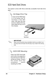
... Chapter 3: Hardware Setup Flip open the tray levers to the hot-swap drive tray and secure it with three externally accessible hard disk drive bays. SCSI Hard Disk Drives The system comes with four screws as shown. Ensure the correct drive tray orientation before you insert it out. The tray will... not fit back into the bay if you slide it the wrong way. SCSI HDD Mounting Place the SCSI hard disk drive to release the tray, then slide the tray out of the HDD bays is a hot-swap tray for mounting a hard...
... Chapter 3: Hardware Setup Flip open the tray levers to the hot-swap drive tray and secure it with three externally accessible hard disk drive bays. SCSI Hard Disk Drives The system comes with four screws as shown. Ensure the correct drive tray orientation before you insert it out. The tray will... not fit back into the bay if you slide it the wrong way. SCSI HDD Mounting Place the SCSI hard disk drive to release the tray, then slide the tray out of the HDD bays is a hot-swap tray for mounting a hard...

AP1400R 1U Server Manual English Edition
Page 41
AP1400R Server User's Manual 41 SCSI Hard Disk Drives HDD Installation After the drive is connected to the motherboard and the backplane. IMPORTANT Make sure that the SCSI cable is secured to the section "Connecting Cables". Refer to the tray, carefully insert the drive into the bay, then push the levers back in place.
AP1400R Server User's Manual 41 SCSI Hard Disk Drives HDD Installation After the drive is connected to the motherboard and the backplane. IMPORTANT Make sure that the SCSI cable is secured to the section "Connecting Cables". Refer to the tray, carefully insert the drive into the bay, then push the levers back in place.