
User Guide
Page 3
Contents Contents iii Safety information vi About this guide viii ASUS contact information x Chapter 1: Product introduction 1.1 System package contents 1-2 1.2 System specifications 1-3 1.3 Front panel features 1-4 1.4 LED information 1-5 1.5 Rear panel features 1-5 1.6 Internal features 1-6 Chapter 2: Hardware setup 2.1 Preparation 2-2 2.2 Removing the side cover 2-2 2.3 Motherboard information 2-4 2.4 Installing a Central Processing Unit (CPU 2-5 2.4.1 Overview 2-5 2.4.2 CPU installation 2-6 2.5 Installing memory modules 2-8 2.5.1 Memory...
Contents Contents iii Safety information vi About this guide viii ASUS contact information x Chapter 1: Product introduction 1.1 System package contents 1-2 1.2 System specifications 1-3 1.3 Front panel features 1-4 1.4 LED information 1-5 1.5 Rear panel features 1-5 1.6 Internal features 1-6 Chapter 2: Hardware setup 2.1 Preparation 2-2 2.2 Removing the side cover 2-2 2.3 Motherboard information 2-4 2.4 Installing a Central Processing Unit (CPU 2-5 2.4.1 Overview 2-5 2.4.2 CPU installation 2-6 2.5 Installing memory modules 2-8 2.5.1 Memory...
User Guide
Page 9
...: Information that you perform certain tasks properly, take note of the standard server/workstation package. ASUS websites The ASUS websites worldwide provide updated information on the P4P800S-E motherboard. 2. Conventions To make sure that may include optional documentations such as CD-ROM manual, warranty... flyers, and others that you MUST follow to complete a task. ASUS P4P800S-E motherboard user guide This guide contains detailed information on ASUS hardware and software products. These documents are not part of the following sources for additional ...
...: Information that you perform certain tasks properly, take note of the standard server/workstation package. ASUS websites The ASUS websites worldwide provide updated information on the P4P800S-E motherboard. 2. Conventions To make sure that may include optional documentations such as CD-ROM manual, warranty... flyers, and others that you MUST follow to complete a task. ASUS P4P800S-E motherboard user guide This guide contains detailed information on ASUS hardware and software products. These documents are not part of the following sources for additional ...
User Guide
Page 12
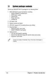
... damaged or missing. 1-2 Chapter 1: Product introduction AP120-E1 support CD including drivers and utilities 5. Documentation • ASUS AP120-E1 user guide • ASUS P4P800S-E user guide 6. System screws and labels 4. Optional items • CPU fan and heatsink assembly • ... disk drive cage with retention base and screws • Expansion card holder Contact your ASUS AP120-E1 package for the following items. 1. ASUS AP120-E1 server/workstation including: • ASUS P4P800S-E motherboard • 250W power supply • Optical drive • Floppy disk drive •...
... damaged or missing. 1-2 Chapter 1: Product introduction AP120-E1 support CD including drivers and utilities 5. Documentation • ASUS AP120-E1 user guide • ASUS P4P800S-E user guide 6. System screws and labels 4. Optional items • CPU fan and heatsink assembly • ... disk drive cage with retention base and screws • Expansion card holder Contact your ASUS AP120-E1 package for the following items. 1. ASUS AP120-E1 server/workstation including: • ASUS P4P800S-E motherboard • 250W power supply • Optical drive • Floppy disk drive •...
User Guide
Page 13
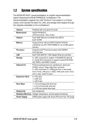
..., one in rear), audio I /O, LAN, and storage technologies through the chipsets embedded on the motherboard. 1.2 System specification The ASUS AP120-E1 server/workstation is a stylish server/workstation system featuring the ASUS P4P800S-E motherboard. Chassis Pedestal with front panel I/O ports Motherboard ASUS P4P800S-E (ATX form factor: 12in x 9.6in) Chipset Intel® 848P Memory Controller Hub (... Storage 2 x IDE connectors to support 4 UltraDMA100 devices 2 x Serial ATA connectors to support 2 serial ATA HDDs with 20-pin ATX and 4-pin 12V plugs ASUS AP120-E1 user guide 1-3
..., one in rear), audio I /O, LAN, and storage technologies through the chipsets embedded on the motherboard. 1.2 System specification The ASUS AP120-E1 server/workstation is a stylish server/workstation system featuring the ASUS P4P800S-E motherboard. Chassis Pedestal with front panel I/O ports Motherboard ASUS P4P800S-E (ATX form factor: 12in x 9.6in) Chipset Intel® 848P Memory Controller Hub (... Storage 2 x IDE connectors to support 4 UltraDMA100 devices 2 x Serial ATA connectors to support 2 serial ATA HDDs with 20-pin ATX and 4-pin 12V plugs ASUS AP120-E1 user guide 1-3
User Guide
Page 15
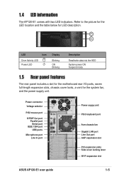
...keyboard port 9cm chassis fan Gigabit LAN port Line Out port AGP expansion slot PCI expansion slots Side cover locking lever Wi-Fi expansion slot ASUS AP120-E1 user guide 1-5 1.4 LED information The AP120-E1 comes with two LED indicators. LED Icon Drive Activity LED Power LED Display ... ON Blinking Description Read/write data into the HDD System power ON Suspend mode 1.5 Rear panel features The rear panel includes a slot for the motherboard rear I/O ports, seven full-length expansion slots, chassis cover locks, a vent for LED description. Refer to the picture for the LED location ...
...keyboard port 9cm chassis fan Gigabit LAN port Line Out port AGP expansion slot PCI expansion slots Side cover locking lever Wi-Fi expansion slot ASUS AP120-E1 user guide 1-5 1.4 LED information The AP120-E1 comes with two LED indicators. LED Icon Drive Activity LED Power LED Display ... ON Blinking Description Read/write data into the HDD System power ON Suspend mode 1.5 Rear panel features The rear panel includes a slot for the motherboard rear I/O ports, seven full-length expansion slots, chassis cover locks, a vent for LED description. Refer to the picture for the LED location ...
User Guide
Page 16
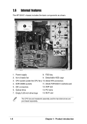
Detachable HDD cage 3. PCI slots 7. Empty 5.25-inch drive bays 14. CPU socket (under the CPU fan) 10. FDD bay 2. 9cm chassis fan 9. Serial ATA connectors 4. DDR DIMM sockets 11. AGP slot 6. Power supply 8. ASUS P4P800S-E motherboard 5. IDE connectors 12. Optical drive 13. Wi-Fi slot The CPU fan and heatswink assembly and the hard disk drives are purchased separately. 1-6 Chapter 1: Product introduction 1.6 Internal features The AP120-E1 chassis includes the basic components as shown. 6 1 7 3 2 8 45 11 12 9 10 13 14 1.
Detachable HDD cage 3. PCI slots 7. Empty 5.25-inch drive bays 14. CPU socket (under the CPU fan) 10. FDD bay 2. 9cm chassis fan 9. Serial ATA connectors 4. DDR DIMM sockets 11. AGP slot 6. Power supply 8. ASUS P4P800S-E motherboard 5. IDE connectors 12. Optical drive 13. Wi-Fi slot The CPU fan and heatswink assembly and the hard disk drives are purchased separately. 1-6 Chapter 1: Product introduction 1.6 Internal features The AP120-E1 chassis includes the basic components as shown. 6 1 7 3 2 8 45 11 12 9 10 13 14 1.
User Guide
Page 20
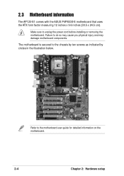
Refer to unplug the power cord before installing or removing the motherboard. Make sure to the motherboard user guide for detailed information on the motherboard. 2-4 Chapter 2: Hardware setup The motherboard is secured to do so may cause you physical injury and may damage motherboard components. Failure to the chassis by ten screws as indicated by circles in the illustration below. 2.3 Motherboard information The AP120-E1 comes with the ASUS P4P800S-E motherboard that uses the ATX form factor measuring 12 inches x 9.6 inches (30.5 x 24.5 cm).
Refer to unplug the power cord before installing or removing the motherboard. Make sure to the motherboard user guide for detailed information on the motherboard. 2-4 Chapter 2: Hardware setup The motherboard is secured to do so may cause you physical injury and may damage motherboard components. Failure to the chassis by ten screws as indicated by circles in the illustration below. 2.3 Motherboard information The AP120-E1 comes with the ASUS P4P800S-E motherboard that uses the ATX form factor measuring 12 inches x 9.6 inches (30.5 x 24.5 cm).
User Guide
Page 21
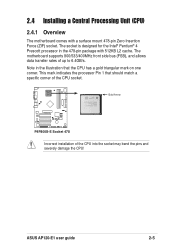
...; P4P800S-E P4P800S-E Socket 478 Incorrect installation of up to 6.4GB/s. The motherboard supports 800/533/400MHz front side bus (FSB), and allows data transfer rates of the CPU into the socket may bend the pins and severely damage the CPU! ASUS AP120-E1 user guide 2-5 Note in the 478-pin package with...
...; P4P800S-E P4P800S-E Socket 478 Incorrect installation of up to 6.4GB/s. The motherboard supports 800/533/400MHz front side bus (FSB), and allows data transfer rates of the CPU into the socket may bend the pins and severely damage the CPU! ASUS AP120-E1 user guide 2-5 Note in the 478-pin package with...

User Guide
Page 22
... socket to prevent bending the pins and damaging the CPU! 5. When the CPU is lifted up to secure the CPU. The lever clicks on the motherboard. 2. 2.4.2 CPU installation Follow these steps to 90°-100° angle, otherwise the CPU does not fit in place. Locate the 478-pin ZIF socket...
... socket to prevent bending the pins and damaging the CPU! 5. When the CPU is lifted up to secure the CPU. The lever clicks on the motherboard. 2. 2.4.2 CPU installation Follow these steps to 90°-100° angle, otherwise the CPU does not fit in place. Locate the 478-pin ZIF socket...

User Guide
Page 23
Install a CPU heatsink and fan following the instructions that came with the heatsink package. ASUS provides an Intel®-certified CPU fan and heatsink assembly as an optional item for details. 7. Hardware monitoring errors may occur if you fail to the CPU_FAN1 connector on the motherboard. Connect the CPU fan cable to plug this connector. CPU fan connector (CPU_FAN1) Don't forget to the "Installation options" chapter for your AP120-E1 system. 6. Refer to connect the CPU fan connector! ASUS AP120-E1 user guide 2-7
Install a CPU heatsink and fan following the instructions that came with the heatsink package. ASUS provides an Intel®-certified CPU fan and heatsink assembly as an optional item for details. 7. Hardware monitoring errors may occur if you fail to the CPU_FAN1 connector on the motherboard. Connect the CPU fan cable to plug this connector. CPU fan connector (CPU_FAN1) Don't forget to the "Installation options" chapter for your AP120-E1 system. 6. Refer to connect the CPU fan connector! ASUS AP120-E1 user guide 2-7
User Guide
Page 24
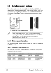
...sockets. 104 Pins 80 Pins ® P4P800S-E DIMM1 DIMM2 DIMM3 P4P800S-E 184-Pin DDR DIMM Sockets Obtain DDR DIMMs only from ASUS qualified vendors to ensure system system stability. Table 1: Qualified DDR400 vendors list This table lists the memory modules that have been tested... You may install 64MB, 128MB, 256MB, 512MB, and 1GB DDR DIMMs into the DIMM sockets. 2.5 Installing memory modules The motherboard comes with this motherboard. Visit http://www.asus.com/products/server/ RAMsupport.htm for use with three (3) Double Data Rate (DDR) Dual Inline Memory Module (DIMM) sockets....
...sockets. 104 Pins 80 Pins ® P4P800S-E DIMM1 DIMM2 DIMM3 P4P800S-E 184-Pin DDR DIMM Sockets Obtain DDR DIMMs only from ASUS qualified vendors to ensure system system stability. Table 1: Qualified DDR400 vendors list This table lists the memory modules that have been tested... You may install 64MB, 128MB, 256MB, 512MB, and 1GB DDR DIMMs into the DIMM sockets. 2.5 Installing memory modules The motherboard comes with this motherboard. Visit http://www.asus.com/products/server/ RAMsupport.htm for use with three (3) Double Data Rate (DDR) Dual Inline Memory Module (DIMM) sockets....
User Guide
Page 25
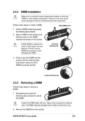
... to remove a DIMM. 1. Unlocked retaining clip 3. Follow these steps to install a DIMM. 1. Support the DIMM lightly with extra force. 2. ASUS AP120-E1 user guide 2-9 2.5.2 DIMM installation Make sure to both the motherboard and the components. Align a DIMM on the socket. Failure to do so may cause severe damage to unplug the power...
... to remove a DIMM. 1. Unlocked retaining clip 3. Follow these steps to install a DIMM. 1. Support the DIMM lightly with extra force. 2. ASUS AP120-E1 user guide 2-9 2.5.2 DIMM installation Make sure to both the motherboard and the components. Align a DIMM on the socket. Failure to do so may cause severe damage to unplug the power...

User Guide
Page 28
...the SATA power cable. Connect a 4-pin plug (female) from the PSU to the power connector at the back of the drive. Refer to the motherboard user guide the correct IDE cable before connecting anIDE cable to the power connector at the back of the SATA connectors. 3. See page 3-6 for ...male) Serial ATA power cable 2-12 Chapter 2: Hardware setup 5 6 5. Connect a 4-pin power plug from the power supply unit (PSU) to a SATA connector on the motherboard. Connect one end of the supplied 7-pin SATA cable to the SATA connector at the back of the drive, then connect the other end to...
...the SATA power cable. Connect a 4-pin plug (female) from the PSU to the power connector at the back of the drive. Refer to the motherboard user guide the correct IDE cable before connecting anIDE cable to the power connector at the back of the SATA connectors. 3. See page 3-6 for ...male) Serial ATA power cable 2-12 Chapter 2: Hardware setup 5 6 5. Connect a 4-pin power plug from the power supply unit (PSU) to a SATA connector on the motherboard. Connect one end of the supplied 7-pin SATA cable to the SATA connector at the back of the drive, then connect the other end to...
User Guide
Page 29
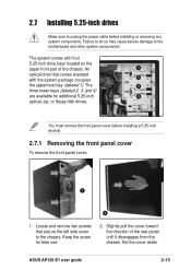
... of the rear panel until it disengages from the chassis. An 1 optical drive that secure the left side cover to the motherboard and other system components! Set the cover aside. ASUS AP120-E1 user guide 2-13 Failure to do so may cause severe damage to the chassis. Slightly pull the cover toward...
... of the rear panel until it disengages from the chassis. An 1 optical drive that secure the left side cover to the motherboard and other system components! Set the cover aside. ASUS AP120-E1 user guide 2-13 Failure to do so may cause severe damage to the chassis. Slightly pull the cover toward...
User Guide
Page 33
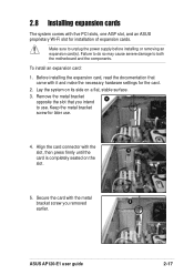
...slot that came with five PCI slots, one AGP slot, and an ASUS proprietary Wi-Fi slot for installation of expansion cards. Lay the system on its side on the slot. 5. Make sure to both the motherboard and the components. Align the card connector with the metal bracket screw... you intend to use . 4. ASUS AP120-E1 user guide 2-17 Secure the card with the slot, then press firmly until the ...
...slot that came with five PCI slots, one AGP slot, and an ASUS proprietary Wi-Fi slot for installation of expansion cards. Lay the system on its side on the slot. 5. Make sure to both the motherboard and the components. Align the card connector with the metal bracket screw... you intend to use . 4. ASUS AP120-E1 user guide 2-17 Secure the card with the slot, then press firmly until the ...
User Guide
Page 35
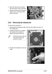
Locate and remove four chassis fan screws at the back of the drive. 3 2.9.2 Removing the chassis fan To remove the chassis fan: 1. Hold the chassis fan with one hand while removing the chassis fan screws. 3. Move the drive bay lock toward the rear panel to the connectors at the rear panel. 2 Keep the screws for later use. Remove the chassis fan, then set aside. 3 ASUS AP120-E1 user guide 2-19 Attach the FDD power and signal cables to secure the drive. 4. 3. Disconnect the chassis fan cable from the CHA_FAN1 connector on the motherboard. 2.
Locate and remove four chassis fan screws at the back of the drive. 3 2.9.2 Removing the chassis fan To remove the chassis fan: 1. Hold the chassis fan with one hand while removing the chassis fan screws. 3. Move the drive bay lock toward the rear panel to the connectors at the rear panel. 2 Keep the screws for later use. Remove the chassis fan, then set aside. 3 ASUS AP120-E1 user guide 2-19 Attach the FDD power and signal cables to secure the drive. 4. 3. Disconnect the chassis fan cable from the CHA_FAN1 connector on the motherboard. 2.
User Guide
Page 36
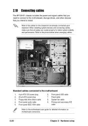
... stability and performance. When installing system devices and connecting cables, make sure that you need to connect to the motherboard, storage drives, and other devices that all cables are routed properly for the chassis kit are already connected upon shipment...when arranging cables. 3 1 2 9 8 6 4 5 7 Standard cables connected to the motherboard user guide for detailed information on motherboard connectors. 2-20 Chapter 2: Hardware setup Primary and secondary IDE cable Refer to the motherboard 1. 4-pin ATX 12V power plug 2. 20-pin ATX power plug 3. System fan cable 9....
... stability and performance. When installing system devices and connecting cables, make sure that you need to connect to the motherboard, storage drives, and other devices that all cables are routed properly for the chassis kit are already connected upon shipment...when arranging cables. 3 1 2 9 8 6 4 5 7 Standard cables connected to the motherboard user guide for detailed information on motherboard connectors. 2-20 Chapter 2: Hardware setup Primary and secondary IDE cable Refer to the motherboard 1. 4-pin ATX 12V power plug 2. 20-pin ATX power plug 3. System fan cable 9....
User Guide
Page 41
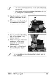
Align the retention bracket with the rails on the motherboard upon purchase. • Do not remove the retention module base when installing the CPU or installing other side of the CPU 2 fan. 3. Follow steps 2 to 5 ... of the retention bracket. 5. Attach the locking lever hook into the retention module hole. 4. Carefully press down the locking lever on the other system components. 2. ASUS AP120-E1 user guide 3-3 Attach the retention bracket hook into the retention module hole to re-install the second retention bracket. 3 4 5 The illustrations are for...
Align the retention bracket with the rails on the motherboard upon purchase. • Do not remove the retention module base when installing the CPU or installing other side of the CPU 2 fan. 3. Follow steps 2 to 5 ... of the retention bracket. 5. Attach the locking lever hook into the retention module hole. 4. Carefully press down the locking lever on the other system components. 2. ASUS AP120-E1 user guide 3-3 Attach the retention bracket hook into the retention module hole to re-install the second retention bracket. 3 4 5 The illustrations are for...

User Guide
Page 44
Use a Serial ATA power cable and adapter for Serial ATA HDD(s) without a 4-pin power connector. 3-6 Chapter 3: Optional components 3 4 3. Connect one end of the 7-pin Serial ATA cable to the connector at the back of the drive(s). 4. Connect a 4-pin power plug from the power supply unit to the SATA connectors on the motherboard. 6. Align the drive cage and retention base rails, then slightly push the cage until it clicks in place 5 6 5. Connect the other end of the Serial ATA cable to the power connector at the back of the drive(s).
Use a Serial ATA power cable and adapter for Serial ATA HDD(s) without a 4-pin power connector. 3-6 Chapter 3: Optional components 3 4 3. Connect one end of the 7-pin Serial ATA cable to the connector at the back of the drive(s). 4. Connect a 4-pin power plug from the power supply unit to the SATA connectors on the motherboard. 6. Align the drive cage and retention base rails, then slightly push the cage until it clicks in place 5 6 5. Connect the other end of the Serial ATA cable to the power connector at the back of the drive(s).

