User Guide
Page 3
Contents Contents iii Safety information vi About this guide viii ASUS contact information x Chapter 1: Product introduction 1.1 System package contents 1-2 1.2 System specifications 1-3 1.3 Front panel features 1-4 1.4 LED information 1-5 1.5 Rear panel features 1-5 ... 2-11 2.7 Installing 5.25-inch drives 2-13 2.7.1 Removing the front panel cover 2-13 2.7.2 Installing additional optical drive(s 2-15 2.8 Installing expansion cards 2-17 2.9 Removing components 2-18 2.9.1 Removing the floppy disk drive 2-18 2.9.2 Removing the chassis fan 2-19 2.10 Connecting cables 2-20 2.11...
Contents Contents iii Safety information vi About this guide viii ASUS contact information x Chapter 1: Product introduction 1.1 System package contents 1-2 1.2 System specifications 1-3 1.3 Front panel features 1-4 1.4 LED information 1-5 1.5 Rear panel features 1-5 ... 2-11 2.7 Installing 5.25-inch drives 2-13 2.7.1 Removing the front panel cover 2-13 2.7.2 Installing additional optical drive(s 2-15 2.8 Installing expansion cards 2-17 2.9 Removing components 2-18 2.9.1 Removing the floppy disk drive 2-18 2.9.2 Removing the chassis fan 2-19 2.10 Connecting cables 2-20 2.11...

User Guide
Page 4
Contents Chapter 3: Installation options 3.1 Installing optional components 3-2 3.1.1 CPU fan and heatsink assembly 3-2 3.1.2 Second hard disk drive cage 3-4 3.1.3 Expansion card holder 3-7 Appendix A.1 Simple fixes A-2 A.2 Power supply specification A-4 iv
Contents Chapter 3: Installation options 3.1 Installing optional components 3-2 3.1.1 CPU fan and heatsink assembly 3-2 3.1.2 Second hard disk drive cage 3-4 3.1.3 Expansion card holder 3-7 Appendix A.1 Simple fixes A-2 A.2 Power supply specification A-4 iv
User Guide
Page 5
Changes or modifications to this unit not expressly approved by one or more of the monitor to the graphics card is subject to the following measures: • Reorient or relocate the receiving antenna. • Increase the separation between the equipment and receiver. • Connect the ...
Changes or modifications to this unit not expressly approved by one or more of the monitor to the graphics card is subject to the following measures: • Reorient or relocate the receiving antenna. • Increase the separation between the equipment and receiver. • Connect the ...
User Guide
Page 12
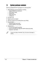
Documentation • ASUS AP120-E1 user guide • ASUS P4P800S-E user guide 6. AP120-E1 support CD including drivers and utilities 5. System screws and labels 4. ASUS AP120-E1 server/workstation including: • ASUS P4P800S-E motherboard • 250W power supply • Optical drive • Floppy disk drive... CPU fan and heatsink assembly • Second hard disk drive cage with retention base and screws • Expansion card holder Contact your ASUS AP120-E1 package for the following items. 1. 1.1 System package contents Check your dealer immediately if any of the items is...
Documentation • ASUS AP120-E1 user guide • ASUS P4P800S-E user guide 6. AP120-E1 support CD including drivers and utilities 5. System screws and labels 4. ASUS AP120-E1 server/workstation including: • ASUS P4P800S-E motherboard • 250W power supply • Optical drive • Floppy disk drive... CPU fan and heatsink assembly • Second hard disk drive cage with retention base and screws • Expansion card holder Contact your ASUS AP120-E1 package for the following items. 1. 1.1 System package contents Check your dealer immediately if any of the items is...
User Guide
Page 18
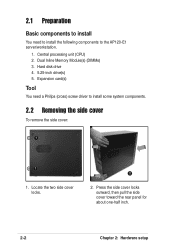
Expansion card(s) Tool You need to install the following components to install some system components. 2.2 Removing the side cover To remove the side cover: 1 1 1. Press the side cover locks outward, then pull the side cover toward the rear panel for about one-half inch. 2-2 Chapter 2: Hardware setup Locate the two side cover locks. 2 2. Dual Inline Memory Module(s) (DIMMs) 3. 2.1 Preparation Basic components to install You need a Philips (cross) screw driver to the AP120-E1 server/workstation. 1. Central processing unit (CPU) 2. Hard disk drive 4. 5.25-inch drive(s) 5.
Expansion card(s) Tool You need to install the following components to install some system components. 2.2 Removing the side cover To remove the side cover: 1 1 1. Press the side cover locks outward, then pull the side cover toward the rear panel for about one-half inch. 2-2 Chapter 2: Hardware setup Locate the two side cover locks. 2 2. Dual Inline Memory Module(s) (DIMMs) 3. 2.1 Preparation Basic components to install You need a Philips (cross) screw driver to the AP120-E1 server/workstation. 1. Central processing unit (CPU) 2. Hard disk drive 4. 5.25-inch drive(s) 5.
User Guide
Page 19
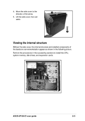
4. Perform the procedures in the succeeding sections to the 4 direction of the barebone server/workstation appear as shown in the following picture. Move the side cover to install the CPU, system memory, disk drives, and expansion cards. ASUS AP120-E1 user guide 2-3 Lift the side cover, then set aside. 5 Viewing the internal structure Without the side cover, the internal structure and installed components of the arrow. 5.
4. Perform the procedures in the succeeding sections to the 4 direction of the barebone server/workstation appear as shown in the following picture. Move the side cover to install the CPU, system memory, disk drives, and expansion cards. ASUS AP120-E1 user guide 2-3 Lift the side cover, then set aside. 5 Viewing the internal structure Without the side cover, the internal structure and installed components of the arrow. 5.
User Guide
Page 33
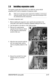
... power supply before installing or removing an expansion card(s). Keep the metal bracket screw for later use . ASUS AP120-E1 user guide 2-17 To install an expansion card: 1. Secure the card with five PCI slots, one AGP slot, and an ASUS proprietary Wi-Fi slot for the card. 2. Align the card connector with it and make the necessary hardware...
... power supply before installing or removing an expansion card(s). Keep the metal bracket screw for later use . ASUS AP120-E1 user guide 2-17 To install an expansion card: 1. Secure the card with five PCI slots, one AGP slot, and an ASUS proprietary Wi-Fi slot for the card. 2. Align the card connector with it and make the necessary hardware...
User Guide
Page 40
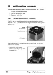
... these instructions to the CPU for the Intel® Pentium® 4 CPU. It provides efficient cooling to install the CPU fan and heatsink assembly. 1. Expansion card holder 3.1.1 CPU fan and heatsink assembly The CPU fan and heatsink assembly is specially designed for stable system performance. CPU fan and heatsink assembly 2. Position... top of the installed CPU. 1 3-2 Chapter 3: Optional components Second hard disk drive cage 3. 3.1 Installing optional components You may install the following optional components to the AP120-E1 system. 1.
... these instructions to the CPU for the Intel® Pentium® 4 CPU. It provides efficient cooling to install the CPU fan and heatsink assembly. 1. Expansion card holder 3.1.1 CPU fan and heatsink assembly The CPU fan and heatsink assembly is specially designed for stable system performance. CPU fan and heatsink assembly 2. Position... top of the installed CPU. 1 3-2 Chapter 3: Optional components Second hard disk drive cage 3. 3.1 Installing optional components You may install the following optional components to the AP120-E1 system. 1.
User Guide
Page 45
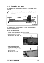
To install the retention bracket: 1. ASUS AP120-E1 user guide 3 3-7 Locking lever Assembly Grooves Card holders Adjusting slots Locking screw The expansion card holder comes with two screws. 4. Lay the system on its side on the chassis floor. 2 3. Place ...the bracket with a retention bracket to keep the expansion card holder in place. 3.1.3 Expansion card holder The expansion card holder provides support for long and heavy PCI and AGP cards. Install all necessary expansion cards before installing the expansion card holder. Locate two retention bracket screw holes on a flat...
To install the retention bracket: 1. ASUS AP120-E1 user guide 3 3-7 Locking lever Assembly Grooves Card holders Adjusting slots Locking screw The expansion card holder comes with two screws. 4. Lay the system on its side on the chassis floor. 2 3. Place ...the bracket with a retention bracket to keep the expansion card holder in place. 3.1.3 Expansion card holder The expansion card holder provides support for long and heavy PCI and AGP cards. Install all necessary expansion cards before installing the expansion card holder. Locate two retention bracket screw holes on a flat...
User Guide
Page 46
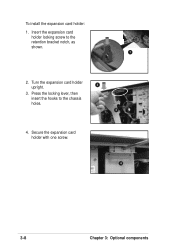
To install the expansion card holder: 1. Secure the expansion card holder with one screw. 4 3-8 Chapter 3: Optional components Press the locking lever, then insert the hooks to the retention bracket notch, as shown. 1 2. Turn the expansion card holder 3 upright. 3. Insert the expansion card holder locking screw to the chassis holes. 2 4.
To install the expansion card holder: 1. Secure the expansion card holder with one screw. 4 3-8 Chapter 3: Optional components Press the locking lever, then insert the hooks to the retention bracket notch, as shown. 1 2. Turn the expansion card holder 3 upright. 3. Insert the expansion card holder locking screw to the chassis holes. 2 4.
User Guide
Page 47
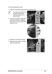
Loosen the screw(s) to adjust the card holder forward or sideward until its groove fits the edge of the expansion card. 3. Fasten the card holder screw(s). 4. The smaller card holder is for long PCI cards. 2. Follow the same steps in holding other card holders are for long AGP cards while the 2 other long expansion. 3 ASUS AP120-E1 user guide 3-9 Place the card holder at level with the expansion card. To hold long expansion cards: 1.
Loosen the screw(s) to adjust the card holder forward or sideward until its groove fits the edge of the expansion card. 3. Fasten the card holder screw(s). 4. The smaller card holder is for long PCI cards. 2. Follow the same steps in holding other card holders are for long AGP cards while the 2 other long expansion. 3 ASUS AP120-E1 user guide 3-9 Place the card holder at level with the expansion card. To hold long expansion cards: 1.

