Asus AP1720-E1 Support and Manuals
Get Help and Manuals for this Asus item
View All Support Options Below
Free Asus AP1720-E1 manuals!
Problems with Asus AP1720-E1?
Ask a Question
Free Asus AP1720-E1 manuals!
Problems with Asus AP1720-E1?
Ask a Question
Popular Asus AP1720-E1 Manual Pages
User Guide - Page 10
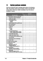
... keys ( 2 pcs.)
5) Bundled CDs • AP1720-E1 support CD • ASWM software CD • TrendMicro® ServerProtect® CD
6) Documentation • ASUS AP1720-E1 user guide • ASUS PC-DL Deluxe user guide
7) Optional items • ASUS AK25 rackmount rail kit • AK25 internal HDD cage (non-hot swap)
HDD Bays AS8 (8 SCSI ) AS4 (4 SCSI) AI4 (4 IDE)
1-2
Chapter 1: Product...
User Guide - Page 11
... bezel and chassis foot stand or roller-wheels. ASUS AP1720-E1 barebone server
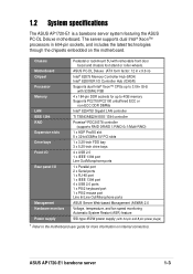
1-3 1.2 System specifications
The ASUS AP1720-E1 is a barebone server system featuring the ASUS PC-DL Deluxe motherboard.
Chassis Motherboard Chipset Processor Memory
LAN IEEE 1394 RAID Expansion slots Drive bays Front I/O
Rear panel I /O Controller Hub (ICH5R)
Supports dual Intel® Xeon™ CPUs up to...
User Guide - Page 17
Chapter 2
This chapter lists the hardware setup procedures that you have to perform when installing or removing system components.
Hardware setup
ASUS AP1720-E1 barebone server
2-1
User Guide - Page 19
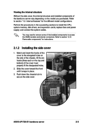
... access the DIMM sockets and internal connectors. Refer to secure the side cover.
1 2
3
ASUS AP1720-E1 barebone server
2-3 Refer to install the CPU, system memory, disk drives, and expansion cards; Perform the procedures in place.
3.
All the six hooks (three each on the model you purchased. Slide the cover toward the front until it snaps in the succeeding...
User Guide - Page 27
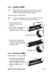
... seated. While supporting the DIMM with...install a DIMM. Align a DIMM on the socket such that the notch on the DIMM matches the break on the socket. Locked Retaining Clip
2.4.3 Removing a DIMM
Follow these steps to remove a DIMM.
1. Remove the DIMM from the socket.
2. ASUS AP1720-E1 barebone server
2-11 Failure to do so may cause damage to section "2.10 Removable components" for instructions...
User Guide - Page 29
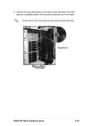
Unhook the hinge-like tab
ASUS AP1720-E1 barebone server
2-13 Do not use too much force when removing the front panel assembly. Hinge-like tabs from the holes on the right side of the front panel to completely detach the front panel assembly from the chassis.
3.
User Guide - Page 31
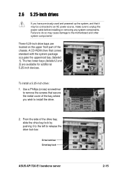
... an AC power source, make sure to install the drive.
2.
Drive lock bar Drive bay lock
ASUS AP1720-E1 barebone server
2-15 Three 5.25-inch drive bays are available for additional
5.25-inch devices.
3
To install a 5.25-inch drive:
1. The two lower bays (labeled 2 and
2
3) are
located on the upper front part of the
chassis. From the side...
User Guide - Page 33
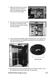
... holes, then push the drive lock to the right to section "2.5.2 Re-installing the front panel assembly" for instructions. On the front panel assembly, detach the plastic bay cover opposite the 5.25-inch drive that the drive and bay holes align as shown.
ASUS AP1720-E1 barebone server
2-17 Bay cover tabs
10. 7. Make sure that you...
User Guide - Page 35
... screws.
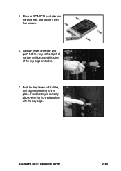
6. Push the tray lever until it all the way to the depth of the bay until just a small fraction of the tray edge protrudes.
7. ASUS AP1720-E1 barebone server
2-19 Place an SCA SCSI hard disk into the drive tray, and secure it with the bay edge.
5. Carefully insert drive tray and push it...
User Guide - Page 37
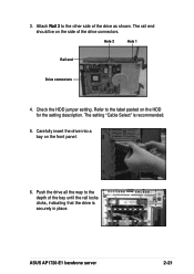
... Rail 2 to the other side of the drive connectors. Check the HDD jumper setting.
ASUS AP1720-E1 barebone server
2-21 3.
The rail end should be on the side of the drive as shown. The setting "Cable Select" is securely in place. Refer to the depth of the bay ...label pasted on the front panel.
6. Carefully insert the drive into a bay on the HDD for the setting description.
User Guide - Page 41
... you wish to install or remove an expansion card in less steps. Make sure to the card and motheboard components!
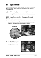
2.8.1 Installing a standard size expansion card
To install a standard size expansion card: 1. Card lock tabs
2. ASUS AP1720-E1 barebone server
2-25 Release the card lock by pressing the center tabs and pushing outward.
Carefully install an expansion card making sure that...
User Guide - Page 43
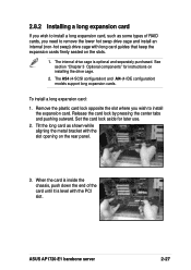
....
ASUS AP1720-E1 barebone server
2-27 See section "Chapter 3 Optional components" for later use. 2. To install a long expansion card: 1. When the card is inside the chassis, push down the end of RAID cards, you need to remove the lower hot swap drive cage and install an internal (non-hot swap) drive cage with the slot opening on the rear panel.
3.
Set...
User Guide - Page 47
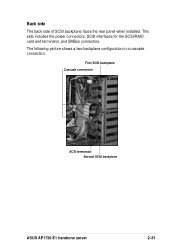
... side includes the power connectors, SCSI interfaces for the SCSI/RAID card and terminator, and SMBus connectors. The following picture shows a two-backplane configuration in a cascade connection. First SCSI backplane Cascade connection
SCSI terminator Second SCSI backplane
ASUS AP1720-E1 barebone server
2-31 Back side
The back side of SCSI backplane faces the rear panel when installed.
User Guide - Page 49
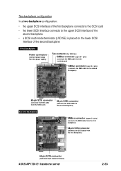
...backplane connects to the SCSI card • the lower SCSI ...card)
68-pin SCSI connector
(connects the SCSI cable to the second backplane)
Second backplane
SMBus connector (upper 6-1 pins)
(connects the SMB cable from the first backplane)
68-pin SCSI connector
(connects the SCSI cable from the first backplane)
68-pin SCSI connector
(with SCSI multi-mode terminator)
ASUS AP1720-E1 barebone server...
User Guide - Page 51
ASUS AP1720-E1 barebone server
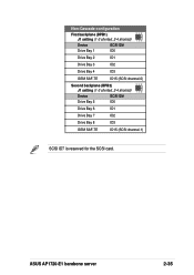
2-35 Non-Cascade configuration
First backplane (BPB1) J1 setting (1-3 shorted, 2-4 shorted)
Device
SCSI ID#
Drive Bay 1
ID0
Drive Bay 2
ID1
Drive Bay 3
ID2
Drive Bay 4
ID3
GEM SAF-TE
ID15 (SCSI channel-0)
Second backplane (BPB2) J1 setting (1-3 shorted, 2-4 shorted)
Device
SCSI ID#
Drive Bay 5
ID0
Drive Bay 6
ID1
Drive Bay 7
ID2
Drive Bay...
Asus AP1720-E1 Reviews
We have not received any reviews for Asus yet.