User Guide
Page 6
... cables are connected. Lithium-Ion Battery Warning CAUTION! This product is equipped with the same or equivalent type recommended by yourself. Use the power cable with the server package. • Before using the server, make sure all cables are correctly connected and the power cables are not damaged. Replace only with a three-wire power cable and plug for the user's safety. Safety information Electrical Safety • Before installing or removing signal cables...
... cables are connected. Lithium-Ion Battery Warning CAUTION! This product is equipped with the same or equivalent type recommended by yourself. Use the power cable with the server package. • Before using the server, make sure all cables are correctly connected and the power cables are not damaged. Replace only with a three-wire power cable and plug for the user's safety. Safety information Electrical Safety • Before installing or removing signal cables...
User Guide
Page 7
... users with the barebone server. Conventions To make sure that you perform certain tasks properly, take note of the AP1720-E1 server. Chapter 2: Hardware setup This chapter lists the hardware setup procedures that you have to complete a task. WARNING: Information to prevent injury to yourself when trying to perform when installing or removing system components. 3. Appendix: Power supply This appendix gives information on front panel and rear panel specifications...
... users with the barebone server. Conventions To make sure that you perform certain tasks properly, take note of the AP1720-E1 server. Chapter 2: Hardware setup This chapter lists the hardware setup procedures that you have to complete a task. WARNING: Information to prevent injury to yourself when trying to perform when installing or removing system components. 3. Appendix: Power supply This appendix gives information on front panel and rear panel specifications...
User Guide
Page 8
References Refer to the ASUS contact information. ASUS PC-DL Deluxe motherboard user guide This manual contains detailed information about the PC-DL Deluxe motherboard. 2. Refer to the following sources for additional information, and for all ASUS hardware and software products. viii ASUS websites The ASUS websites worldwide provide updated information for product and software updates. 1.
References Refer to the ASUS contact information. ASUS PC-DL Deluxe motherboard user guide This manual contains detailed information about the PC-DL Deluxe motherboard. 2. Refer to the following sources for additional information, and for all ASUS hardware and software products. viii ASUS websites The ASUS websites worldwide provide updated information for product and software updates. 1.
User Guide
Page 10
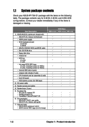
...; 450W power supply • SCSI backplane board (2 pieces) (1 piece) • ASUS U160/320 SCSI card/SCSI cable • 52x CD-ROM drive • floppy disk drive • chassis fan • HDD fan (2 units) (1 unit) • hot-swap SCSI HDD trays (8 units, including screws for HDDs) (4 units, including screws for HDDs) • internal HDD rails (4 pairs) • chassis roller wheels (4 sets) • CPU heatsink and fan assembly (2 sets) • front I/O board • HDD dummy covers (for 8-SCSI, 4-SCSI, and 4-IDE HDD configurations...
...; 450W power supply • SCSI backplane board (2 pieces) (1 piece) • ASUS U160/320 SCSI card/SCSI cable • 52x CD-ROM drive • floppy disk drive • chassis fan • HDD fan (2 units) (1 unit) • hot-swap SCSI HDD trays (8 units, including screws for HDDs) (4 units, including screws for HDDs) • internal HDD rails (4 pairs) • chassis roller wheels (4 sets) • CPU heatsink and fan assembly (2 sets) • front I/O board • HDD dummy covers (for 8-SCSI, 4-SCSI, and 4-IDE HDD configurations...
User Guide
Page 11
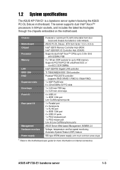
...-bit/33Mhz 5V PCI slots 1 x 3.25-inch FDD bay 3 x 5.25-inch drive bays 4 x USB 2.0 1 x IEEE 1394 port Line Out/Microphone ports 1 x Parallel port 2 x Serial ports 1 x RJ-45 port 1 x IEEE 1394 port 4 x USB 2.0 ports 1 x PS/2 keyboard port 1 x PS/2 mouse port Line In/Line Out/Microphone ports ASUS Server Web-based Management (ASWM) 2.0 Voltage, temperature, and fan speed monitoring Automatic System Restart (ASR) feature SSI-type 450W power supply (with removable front door bezel and chassis foot stand or roller-wheels. ASUS AP1720-E1 barebone server...
...-bit/33Mhz 5V PCI slots 1 x 3.25-inch FDD bay 3 x 5.25-inch drive bays 4 x USB 2.0 1 x IEEE 1394 port Line Out/Microphone ports 1 x Parallel port 2 x Serial ports 1 x RJ-45 port 1 x IEEE 1394 port 4 x USB 2.0 ports 1 x PS/2 keyboard port 1 x PS/2 mouse port Line In/Line Out/Microphone ports ASUS Server Web-based Management (ASWM) 2.0 Voltage, temperature, and fan speed monitoring Automatic System Restart (ASR) feature SSI-type 450W power supply (with removable front door bezel and chassis foot stand or roller-wheels. ASUS AP1720-E1 barebone server...
User Guide
Page 12
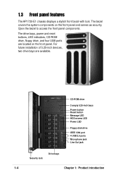
... covers the system components on the front panel. The drive bays, power and reset buttons, LED indicators, CD-ROM drive, floppy drive, and four USB ports are available. For future installation of 5.25-inch devices, two drive bays are located on the front panel and serves as security. 1.3 Front panel features The AP1720-E1 chassis displays a stylish front bezel with lock. Open the bezel to access the front panel components. CD-ROM drive 2 empty 5.25-inch bays Power button Reset button Message LED...
... covers the system components on the front panel. The drive bays, power and reset buttons, LED indicators, CD-ROM drive, floppy drive, and four USB ports are available. For future installation of 5.25-inch devices, two drive bays are located on the front panel and serves as security. 1.3 Front panel features The AP1720-E1 chassis displays a stylish front bezel with lock. Open the bezel to access the front panel components. CD-ROM drive 2 empty 5.25-inch bays Power button Reset button Message LED...
User Guide
Page 13
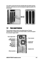
Power supply module P/S2 mouse port P/S2 keyboard port Parallel port Serial ports IEEE 1394 port 4 USB 2.0 ports Gigabit LAN port Audio ports SCSI port (optional) Power connector 12cm fan vent Chassis lock Expansion slots ASUS AP1720-E1 barebone server 1-5 If you wish to access front I/O ports and floppy disk drive without opening the bezel, hold the tab and move the sliding panel (rightmost panel) to the left as shown. 1.4 Rear panel features The rear panel includes a slot for the motherboard rear I/O ports, expansion slots, a chassis lock and intrusion switch, a vent for the system fan, ...
Power supply module P/S2 mouse port P/S2 keyboard port Parallel port Serial ports IEEE 1394 port 4 USB 2.0 ports Gigabit LAN port Audio ports SCSI port (optional) Power connector 12cm fan vent Chassis lock Expansion slots ASUS AP1720-E1 barebone server 1-5 If you wish to access front I/O ports and floppy disk drive without opening the bezel, hold the tab and move the sliding panel (rightmost panel) to the left as shown. 1.4 Rear panel features The rear panel includes a slot for the motherboard rear I/O ports, expansion slots, a chassis lock and intrusion switch, a vent for the system fan, ...
User Guide
Page 14
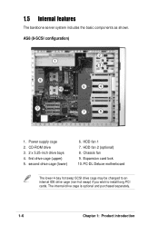
... barebone server system includes the basic components as shown. first drive cage (upper) 5. Power supply cage 2. The internal drive cage is optional and purchased separately. 1-6 Chapter 1: Product introduction second drive cage (lower) 6. Expansion card lock 10. PC-DL Deluxe motherboard The lower 4-bay hot swap SCSI drive cage may be changed to an internal IDE drive cage (non-hot swap) if you wish to install long PCI cards. HDD fan 1 7. AS8 (8-SCSI configuration...
... barebone server system includes the basic components as shown. first drive cage (upper) 5. Power supply cage 2. The internal drive cage is optional and purchased separately. 1-6 Chapter 1: Product introduction second drive cage (lower) 6. Expansion card lock 10. PC-DL Deluxe motherboard The lower 4-bay hot swap SCSI drive cage may be changed to an internal IDE drive cage (non-hot swap) if you wish to install long PCI cards. HDD fan 1 7. AS8 (8-SCSI configuration...
User Guide
Page 16
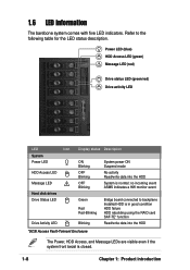
... backplane Installed HDD is in good condition HDD failure HDD rebuilding using the RAID card SAF-TE* function Read/write data into the HDD System is closed. 1-8 Chapter 1: Product introduction Power LED (blue) HDD Access LED (green) ! no incoming event ASMS indicates a HW monitor event Green Red Red-Blinking Blinking Bridge board connected to the following table for the LED status description. 1.6 LED information The barebone system comes with five LED indicators. Message LED...
... backplane Installed HDD is in good condition HDD failure HDD rebuilding using the RAID card SAF-TE* function Read/write data into the HDD System is closed. 1-8 Chapter 1: Product introduction Power LED (blue) HDD Access LED (green) ! no incoming event ASMS indicates a HW monitor event Green Red Red-Blinking Blinking Bridge board connected to the following table for the LED status description. 1.6 LED information The barebone system comes with five LED indicators. Message LED...
User Guide
Page 19
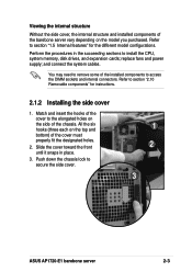
replace fans and power supply; Perform the procedures in place. 3. Push down the chassis lock to access the DIMM sockets and internal connectors. and connect the system cables. Refer to section "1.5 Internal features" for instructions. 2.1.2 Installing the side cover 1. Refer to section "2.10 Removable components" for the different model configurations. All the six hooks (three each on the model you purchased. You may need to install the CPU, system memory, disk drives, and expansion cards; Viewing the internal structure...
replace fans and power supply; Perform the procedures in place. 3. Push down the chassis lock to access the DIMM sockets and internal connectors. and connect the system cables. Refer to section "1.5 Internal features" for instructions. 2.1.2 Installing the side cover 1. Refer to section "2.10 Removable components" for the different model configurations. All the six hooks (three each on the model you purchased. You may need to install the CPU, system memory, disk drives, and expansion cards; Viewing the internal structure...
User Guide
Page 23
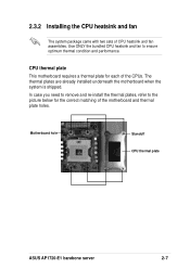
... installed underneath the motherboard when the system is shipped. Motherboard hole Standoff CPU thermal plate ASUS AP1720-E1 barebone server 2-7 CPU thermal plate This motherboard requires a thermal plate for the correct matching of CPU heatsink and fan assemblies. Use ONLY the bundled CPU heatsink and fan to the picture below for each of the CPUs. 2.3.2 Installing the CPU heatsink and fan The system package came with two sets of the motherboard...
... installed underneath the motherboard when the system is shipped. Motherboard hole Standoff CPU thermal plate ASUS AP1720-E1 barebone server 2-7 CPU thermal plate This motherboard requires a thermal plate for the correct matching of CPU heatsink and fan assemblies. Use ONLY the bundled CPU heatsink and fan to the picture below for each of the CPUs. 2.3.2 Installing the CPU heatsink and fan The system package came with two sets of the motherboard...
User Guide
Page 25
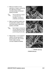
... and the fan power cable plug is slotted so it . 4. CPUFAN1 cable plug CPUFAN2 cable plug ASUS AP1720-E1 barebone server 2-9 If it doesn't fit completely, try reversing it fits only in place, connect the fan cable plug to connect the CPU fan cable plug. Don't forget to the fan connector on the motherboard labeled CPUFAN1. The fan cable plug is properly connected. When the heatsink and fan assembly is in one orientation. Hardware monitoring errors may...
... and the fan power cable plug is slotted so it . 4. CPUFAN1 cable plug CPUFAN2 cable plug ASUS AP1720-E1 barebone server 2-9 If it doesn't fit completely, try reversing it fits only in place, connect the fan cable plug to connect the CPU fan cable plug. Don't forget to the fan connector on the motherboard labeled CPUFAN1. The fan cable plug is properly connected. When the heatsink and fan assembly is in one orientation. Hardware monitoring errors may...
User Guide
Page 31
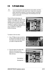
... uppermost bay (labeled 1). Failure to do so may be connected to an AC power source, make sure to unplug the power cable before installing or removing any system components. Three 5.25-inch drive bays are available for additional 5.25-inch devices. 3 To install a 5.25-inch drive: 1. Drive lock bar Drive bay lock ASUS AP1720-E1 barebone server 2-15 2.6 5.25-inch drives If you wish to install the drive. 2. The two...
... uppermost bay (labeled 1). Failure to do so may be connected to an AC power source, make sure to unplug the power cable before installing or removing any system components. Three 5.25-inch drive bays are available for additional 5.25-inch devices. 3 To install a 5.25-inch drive: 1. Drive lock bar Drive bay lock ASUS AP1720-E1 barebone server 2-15 2.6 5.25-inch drives If you wish to install the drive. 2. The two...
User Guide
Page 39
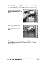
Connect the IDE and power cables to section "21.2 Installing the side cover." Re-install the side cover when done. ASUS AP1720-E1 barebone server 2-23 Carefully insert the drive into a bay on the back of the drive. 7. Check the HDD jumper setting. Follow steps 2 to 5 if you wish to the label pasted on the HDD for the setting description. Refer to install other hard disk drives. 8. The setting "Cable Select" is recommended. 5. Refer to their corresponding connectors on the second drive cage as shown. 6. 4.
Connect the IDE and power cables to section "21.2 Installing the side cover." Re-install the side cover when done. ASUS AP1720-E1 barebone server 2-23 Carefully insert the drive into a bay on the back of the drive. 7. Check the HDD jumper setting. Follow steps 2 to 5 if you wish to the label pasted on the HDD for the setting description. Refer to install other hard disk drives. 8. The setting "Cable Select" is recommended. 5. Refer to their corresponding connectors on the second drive cage as shown. 6. 4.
User Guide
Page 43
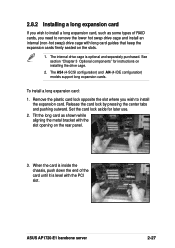
ASUS AP1720-E1 barebone server 2-27 The internal drive cage is level with the PCI slot. The AS4 (4-SCSI configuration) and AI4 (4-IDE configuration) models support long expansion cards. Tilt the long card as some types of the card until it is optional and separately purchased. To install a long expansion card: 1. Remove the plastic card lock opposite the slot where you wish to install the expansion card. Release the card lock by pressing the center tabs and pushing outward...
ASUS AP1720-E1 barebone server 2-27 The internal drive cage is level with the PCI slot. The AS4 (4-SCSI configuration) and AI4 (4-IDE configuration) models support long expansion cards. Tilt the long card as some types of the card until it is optional and separately purchased. To install a long expansion card: 1. Remove the plastic card lock opposite the slot where you wish to install the expansion card. Release the card lock by pressing the center tabs and pushing outward...
User Guide
Page 45
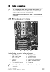
... cables to ensure correct cable connections. 2.9.1 Motherboard connections 2 1 3 4 10 8 11 5 6 7 9 12 Standard cables connected to backplane 12. Front panel 1394 8. Front panel LEDs 10. Secondary IDE (optical drive) 11. SMBus panel to the motherboard 1. 24-pin ATX power 2. 8-pin 12V AUX power 3. Floppy disk Refer to install additional devices. ASUS AP1720-E1 barebone server 2-29 HDD fan 2 5. Front panel USB (4 ports) 7. Chassis intrusion 9. You do not need to disconnect these cables unless you will remove preinstalled components to the motherboard user guide...
... cables to ensure correct cable connections. 2.9.1 Motherboard connections 2 1 3 4 10 8 11 5 6 7 9 12 Standard cables connected to backplane 12. Front panel 1394 8. Front panel LEDs 10. Secondary IDE (optical drive) 11. SMBus panel to the motherboard 1. 24-pin ATX power 2. 8-pin 12V AUX power 3. Floppy disk Refer to install additional devices. ASUS AP1720-E1 barebone server 2-29 HDD fan 2 5. Front panel USB (4 ports) 7. Chassis intrusion 9. You do not need to disconnect these cables unless you will remove preinstalled components to the motherboard user guide...
User Guide
Page 46
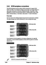
... server supports a hot swap configuration for the hot swap drive trays. Second backplane Disk drive 5 SCSI ID = 4 HDD status LEDs Disk drive 6 SCSI ID = 5 Disk drive 7 SCSI ID = 6 HDD activity LEDs Disk drive 8 SCSI ID = 8 SCSI ID7 is reserved for the SCSI card. 2-30 Chapter 2: Hardware setup See section "1.6 LED information." The LEDs on the backplane connect to the front panel LEDs to support SCA SCSI hard disks. 2.9.2 SCSI backplane connections The SCSI backplane has four 68-pin SCSI connectors to indicate HDD access, HDD failure, thermal failure, or fan failure. The...
... server supports a hot swap configuration for the hot swap drive trays. Second backplane Disk drive 5 SCSI ID = 4 HDD status LEDs Disk drive 6 SCSI ID = 5 Disk drive 7 SCSI ID = 6 HDD activity LEDs Disk drive 8 SCSI ID = 8 SCSI ID7 is reserved for the SCSI card. 2-30 Chapter 2: Hardware setup See section "1.6 LED information." The LEDs on the backplane connect to the front panel LEDs to support SCA SCSI hard disks. 2.9.2 SCSI backplane connections The SCSI backplane has four 68-pin SCSI connectors to indicate HDD access, HDD failure, thermal failure, or fan failure. The...

User Guide
Page 52
... corresponding holes on the rear panel. 3. Power supply module 5. Chassis fan 2. Front I/O board 2.10.1 Chassis fan To remove the chassis fan: 1. HDD fans 3. Floppy disk drive 6. Re-connect the 3-pin fan cable from the connector CHA_FAN1 on the outer corners of the system fan, then pull the fan out of the chassis. SCSI backplanes 4. Press the tabs on the motherboard. 2. 2.10 Removable components You may need to remove previously installed system components when installing or removing system devices, or when you need...
... corresponding holes on the rear panel. 3. Power supply module 5. Chassis fan 2. Front I/O board 2.10.1 Chassis fan To remove the chassis fan: 1. HDD fans 3. Floppy disk drive 6. Re-connect the 3-pin fan cable from the connector CHA_FAN1 on the outer corners of the system fan, then pull the fan out of the chassis. SCSI backplanes 4. Press the tabs on the motherboard. 2. 2.10 Removable components You may need to remove previously installed system components when installing or removing system devices, or when you need...
User Guide
Page 68
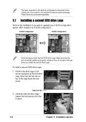
... routed so they do not get in the standard barebone system package. Note that the pre-connected cables are not included in the way when you wish to upgrade your 4-SCSI configuration system (AS4 model) to an 8-SCSI configuration. 4-SCSI configuration 8-SCSI configuration Clear the space under the first SCSI drive cage. Make sure that the lock tab on top of the cage faces the rear panel.
... routed so they do not get in the standard barebone system package. Note that the pre-connected cables are not included in the way when you wish to upgrade your 4-SCSI configuration system (AS4 model) to an 8-SCSI configuration. 4-SCSI configuration 8-SCSI configuration Clear the space under the first SCSI drive cage. Make sure that the lock tab on top of the cage faces the rear panel.
User Guide
Page 71
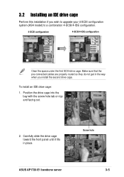
... panel until it fits in the way when you wish to upgrade your 4-SCSI configuration system (AS4 model) to a combination 4-SCSI/4-IDE configuration. 4-SCSI configuration 4-SCSI/4-IDE configuration Clear the space under the first SCSI drive cage. Make sure that the pre-connected cables are properly routed so they do not get in place. Screw hole ASUS AP1720-E1 barebone server 3-5 To install an IDE drive cage: 1. 3.2 Installing an IDE drive cage Perform this installation...
... panel until it fits in the way when you wish to upgrade your 4-SCSI configuration system (AS4 model) to a combination 4-SCSI/4-IDE configuration. 4-SCSI configuration 4-SCSI/4-IDE configuration Clear the space under the first SCSI drive cage. Make sure that the pre-connected cables are properly routed so they do not get in place. Screw hole ASUS AP1720-E1 barebone server 3-5 To install an IDE drive cage: 1. 3.2 Installing an IDE drive cage Perform this installation...


