User Guide
Page 3
...CPU 2-5 2.4.1 Overview 2-5 2.4.2 CPU installation 2-6 2.5 Installing memory modules 2-8 2.5.1 Memory configurations 2-8 2.5.2 DIMM installation 2-9 2.5.3 Removing a DIMM 2-9 2.6 Installing a hard disk drive 2-10 2.6.1 Qualified hard disk drives 2-10 2.6.2 Hard disk drive installation 2-11 2.7 Installing 5.25-inch drives 2-13 2.7.1 Removing the front panel cover 2-13 2.7.2 Installing additional optical drive(s 2-15 2.8 Installing expansion cards 2-17 2.9 Removing components 2-18 2.9.1 Removing the floppy disk drive 2-18 2.9.2 Removing the chassis fan 2-19 2.10 Connecting cables...
...CPU 2-5 2.4.1 Overview 2-5 2.4.2 CPU installation 2-6 2.5 Installing memory modules 2-8 2.5.1 Memory configurations 2-8 2.5.2 DIMM installation 2-9 2.5.3 Removing a DIMM 2-9 2.6 Installing a hard disk drive 2-10 2.6.1 Qualified hard disk drives 2-10 2.6.2 Hard disk drive installation 2-11 2.7 Installing 5.25-inch drives 2-13 2.7.1 Removing the front panel cover 2-13 2.7.2 Installing additional optical drive(s 2-15 2.8 Installing expansion cards 2-17 2.9 Removing components 2-18 2.9.1 Removing the floppy disk drive 2-18 2.9.2 Removing the chassis fan 2-19 2.10 Connecting cables...

User Guide
Page 4
Contents Chapter 3: Installation options 3.1 Installing optional components 3-2 3.1.1 CPU fan and heatsink assembly 3-2 3.1.2 Second hard disk drive cage 3-4 3.1.3 Expansion card holder 3-7 Appendix A.1 Simple fixes A-2 A.2 Power supply specification A-4 iv
Contents Chapter 3: Installation options 3.1 Installing optional components 3-2 3.1.1 CPU fan and heatsink assembly 3-2 3.1.2 Second hard disk drive cage 3-4 3.1.3 Expansion card holder 3-7 Appendix A.1 Simple fixes A-2 A.2 Power supply specification A-4 iv
User Guide
Page 6
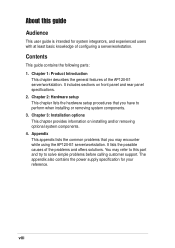
... installing or removing signal cables, ensure that the power cables for the devices are unplugged before the signal cables are connected. If any additional devices to or from the existing system before you add a device. • If the power supply is broken, do not try to avoid electrical shock. This product is detected, contact your dealer. Use the power cable with a three-wire power cable and plug for the user...
... installing or removing signal cables, ensure that the power cables for the devices are unplugged before the signal cables are connected. If any additional devices to or from the existing system before you add a device. • If the power supply is broken, do not try to avoid electrical shock. This product is detected, contact your dealer. Use the power cable with a three-wire power cable and plug for the user...
User Guide
Page 8
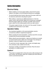
... front panel and rear panel specifications. 2. It lists the possible causes of the AP120-E1 server/workstation. The appendix also contains the power supply specification for system integrators, and experienced users with at least basic knowledge of configuring a server/workstation. Chapter 1: Product Introduction This chapter describes the general features of the problems and offers solutions. viii Contents This guide contains the following parts: 1. Chapter 2: Hardware setup This chapter lists the hardware setup...
... front panel and rear panel specifications. 2. It lists the possible causes of the AP120-E1 server/workstation. The appendix also contains the power supply specification for system integrators, and experienced users with at least basic knowledge of configuring a server/workstation. Chapter 1: Product Introduction This chapter describes the general features of the problems and offers solutions. viii Contents This guide contains the following parts: 1. Chapter 2: Hardware setup This chapter lists the hardware setup...
User Guide
Page 12
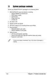
... missing. 1-2 Chapter 1: Product introduction ASUS AP120-E1 server/workstation including: • ASUS P4P800S-E motherboard • 250W power supply • Optical drive • Floppy disk drive • Chassis fan 2. AP120-E1 support CD including drivers and utilities 5. Documentation • ASUS AP120-E1 user guide • ASUS P4P800S-E user guide 6. System screws and labels 4. Optional items • CPU fan and heatsink assembly • Second hard disk drive cage with retention base and screws • Expansion card holder Contact your ASUS AP120-E1 package for the following...
... missing. 1-2 Chapter 1: Product introduction ASUS AP120-E1 server/workstation including: • ASUS P4P800S-E motherboard • 250W power supply • Optical drive • Floppy disk drive • Chassis fan 2. AP120-E1 support CD including drivers and utilities 5. Documentation • ASUS AP120-E1 user guide • ASUS P4P800S-E user guide 6. System screws and labels 4. Optional items • CPU fan and heatsink assembly • Second hard disk drive cage with retention base and screws • Expansion card holder Contact your ASUS AP120-E1 package for the following...
User Guide
Page 13
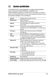
...Storage 2 x IDE connectors to support 4 UltraDMA100 devices 2 x Serial ATA connectors to support 2 serial ATA HDDs with 20-pin ATX and 4-pin 12V plugs ASUS AP120-E1 user guide 1-3 The server/workstation supports the Intel® Pentium® 4 processor in a 478-pin socket, and includes the latest I /O ports Expansion Slots 5 x PCI slots 1 x AGP slot 1 x Wi-Fi slot Drive Bays 1 x 3.5-inch floppy disk drive bay 1 x 3.5-inch hard disk drive bay 4 x 5.25-inch optical drive bays Chassis fan 9cm chassis fan Hardware Monitors Voltage, temperature, and fan speed monitoring Power Supply...
...Storage 2 x IDE connectors to support 4 UltraDMA100 devices 2 x Serial ATA connectors to support 2 serial ATA HDDs with 20-pin ATX and 4-pin 12V plugs ASUS AP120-E1 user guide 1-3 The server/workstation supports the Intel® Pentium® 4 processor in a 478-pin socket, and includes the latest I /O ports Expansion Slots 5 x PCI slots 1 x AGP slot 1 x Wi-Fi slot Drive Bays 1 x 3.5-inch floppy disk drive bay 1 x 3.5-inch hard disk drive bay 4 x 5.25-inch optical drive bays Chassis fan 9cm chassis fan Hardware Monitors Voltage, temperature, and fan speed monitoring Power Supply...
User Guide
Page 14
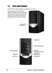
Flip the front panel I/O ports cover to access the front panel USB, IEEE 1394, and audio I /O ports cover Floppy disk drive USB ports Line In port Optical drive Empty 5.25-inch bays HDD LED Power button and LED Reset button IEEE 1394 port Line Out port 1-4 Chapter 1: Product introduction Front panel I /O ports. The power button, LED indicators, optical, and floppy drives are located on the front panel. 1.3 Front panel features The AP120-E1 chassis displays a black stylish front panel.
Flip the front panel I/O ports cover to access the front panel USB, IEEE 1394, and audio I /O ports cover Floppy disk drive USB ports Line In port Optical drive Empty 5.25-inch bays HDD LED Power button and LED Reset button IEEE 1394 port Line Out port 1-4 Chapter 1: Product introduction Front panel I /O ports. The power button, LED indicators, optical, and floppy drives are located on the front panel. 1.3 Front panel features The AP120-E1 chassis displays a black stylish front panel.
User Guide
Page 15
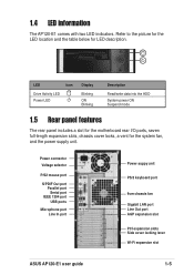
... power supply unit. Power connector Voltage selector P/S2 mouse port S/PDIF Out port Parallel port Serial port IEEE 1394 port USB ports Microphone port Line In port Power suppy unit PS/2 keyboard port 9cm chassis fan Gigabit LAN port Line Out port AGP expansion slot PCI expansion slots Side cover locking lever Wi-Fi expansion slot ASUS AP120-E1 user guide 1-5 LED Icon Drive Activity LED Power LED Display Blinking ON Blinking Description Read/write data into the HDD System power ON Suspend mode 1.5 Rear panel features The rear panel includes a slot for the motherboard rear I/O ports...
... power supply unit. Power connector Voltage selector P/S2 mouse port S/PDIF Out port Parallel port Serial port IEEE 1394 port USB ports Microphone port Line In port Power suppy unit PS/2 keyboard port 9cm chassis fan Gigabit LAN port Line Out port AGP expansion slot PCI expansion slots Side cover locking lever Wi-Fi expansion slot ASUS AP120-E1 user guide 1-5 LED Icon Drive Activity LED Power LED Display Blinking ON Blinking Description Read/write data into the HDD System power ON Suspend mode 1.5 Rear panel features The rear panel includes a slot for the motherboard rear I/O ports...
User Guide
Page 19
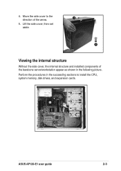
4. Move the side cover to install the CPU, system memory, disk drives, and expansion cards. Lift the side cover, then set aside. 5 Viewing the internal structure Without the side cover, the internal structure and installed components of the barebone server/workstation appear as shown in the succeeding sections to the 4 direction of the arrow. 5. Perform the procedures in the following picture. ASUS AP120-E1 user guide 2-3
4. Move the side cover to install the CPU, system memory, disk drives, and expansion cards. Lift the side cover, then set aside. 5 Viewing the internal structure Without the side cover, the internal structure and installed components of the barebone server/workstation appear as shown in the succeeding sections to the 4 direction of the arrow. 5. Perform the procedures in the following picture. ASUS AP120-E1 user guide 2-3
User Guide
Page 24
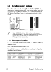
....asus.com/products/server/ RAMsupport.htm for use with three (3) Double Data Rate (DDR) Dual Inline Memory Module (DIMM) sockets. 2.5 Installing memory modules The motherboard comes with this motherboard. Size 256MB 256MB 512MB 512MB Vendor Apacer Trancend Infineon Kingston Part Number 77.10638.465 V58C2256804SAT75 HYS64D64320GU-5-B KVR333X64C25/512 Chip Brand SAMSUNG Trancend Infineon Kingston Chip Number K4H560838D V58C2256804SAT75 HYB25D256800BT-5 D3208DH1T-6 2-8 Chapter 2: Hardware setup The DDR400 Qualified Vendors List...
....asus.com/products/server/ RAMsupport.htm for use with three (3) Double Data Rate (DDR) Dual Inline Memory Module (DIMM) sockets. 2.5 Installing memory modules The motherboard comes with this motherboard. Size 256MB 256MB 512MB 512MB Vendor Apacer Trancend Infineon Kingston Part Number 77.10638.465 V58C2256804SAT75 HYS64D64320GU-5-B KVR333X64C25/512 Chip Brand SAMSUNG Trancend Infineon Kingston Chip Number K4H560838D V58C2256804SAT75 HYB25D256800BT-5 D3208DH1T-6 2-8 Chapter 2: Hardware setup The DDR400 Qualified Vendors List...
User Guide
Page 25
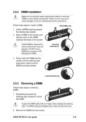
... unlock the DIMM. Simultaneously press the retaining clips outward to avoid damaging the DIMM. DO NOT force a DIMM into the socket until the retaining clips snap back in only one direction. Unlocked retaining clip 3. Follow these steps to both the motherboard and the components. 2.5.2 DIMM installation Make sure to install a DIMM. 1. Align a DIMM on the socket. ASUS AP120-E1 user guide 2-9 Remove the DIMM from the...
... unlock the DIMM. Simultaneously press the retaining clips outward to avoid damaging the DIMM. DO NOT force a DIMM into the socket until the retaining clips snap back in only one direction. Unlocked retaining clip 3. Follow these steps to both the motherboard and the components. 2.5.2 DIMM installation Make sure to install a DIMM. 1. Align a DIMM on the socket. ASUS AP120-E1 user guide 2-9 Remove the DIMM from the...
User Guide
Page 26
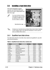
... IDE SATA SATA SATA SATA SATA Speed 7200rpm 7200rpm 7200rpm 7200rpm 7200rpm 7200rpm 7200rpm 7200rpm 7200rpm 7200rpm 7200rpm 7200rpm 7200rpm Capacity 80GB 120GB 80GB 80GB 120GB 160GB 160GB 180GB 80GB 120GB 160GB 80GB 120GB 2-10 Chapter 2: Hardware setup Refer to set the drive as Master/Slave device before installing it to install an additional HDD. 2.6 Installing a hard disk drive The server/workstation system supports one IDE/Serial ATA hard disk drive through a detachable hard disk drive...
... IDE SATA SATA SATA SATA SATA Speed 7200rpm 7200rpm 7200rpm 7200rpm 7200rpm 7200rpm 7200rpm 7200rpm 7200rpm 7200rpm 7200rpm 7200rpm 7200rpm Capacity 80GB 120GB 80GB 80GB 120GB 160GB 160GB 180GB 80GB 120GB 160GB 80GB 120GB 2-10 Chapter 2: Hardware setup Refer to set the drive as Master/Slave device before installing it to install an additional HDD. 2.6 Installing a hard disk drive The server/workstation system supports one IDE/Serial ATA hard disk drive through a detachable hard disk drive...
User Guide
Page 27
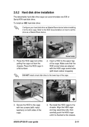
... surface. 2. To install an IDE hard disk drive: Configure your hard disk drive as a Master/Slave device. 1 2 Screw holes 1. ASUS AP120-E1 user guide 2-11 2.6.2 Hard disk drive installation The detachable hard disk drive cage can accommodate one IDE or Serial ATA hard disk drive. DO NOT install a hard disk drive to the cage with two screws (with black rubber stoppers). Secure the HDD to the lower bay of the cage. Re-install the HDD cage to the chassis. Make sure...
... surface. 2. To install an IDE hard disk drive: Configure your hard disk drive as a Master/Slave device. 1 2 Screw holes 1. ASUS AP120-E1 user guide 2-11 2.6.2 Hard disk drive installation The detachable hard disk drive cage can accommodate one IDE or Serial ATA hard disk drive. DO NOT install a hard disk drive to the cage with two screws (with black rubber stoppers). Secure the HDD to the lower bay of the cage. Re-install the HDD cage to the chassis. Make sure...
User Guide
Page 29
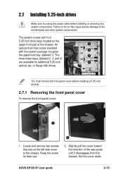
... removing any system components. ASUS AP120-E1 user guide 2-13 Keep the screw for additional 5.25-inch 4 optical, zip, or floppy disk drives. Failure to do so may cause severe damage to unplug the power cable before installing a 5.25-inch drive(s). 2.7.1 Removing the front panel cover To remove the front panel cover: 1 2 1. Locate and remove two screws that comes standard with four 5.25-inch drive bays located on the upper front part of the rear panel...
... removing any system components. ASUS AP120-E1 user guide 2-13 Keep the screw for additional 5.25-inch 4 optical, zip, or floppy disk drives. Failure to do so may cause severe damage to unplug the power cable before installing a 5.25-inch drive(s). 2.7.1 Removing the front panel cover To remove the front panel cover: 1 2 1. Locate and remove two screws that comes standard with four 5.25-inch drive bays located on the upper front part of the rear panel...
User Guide
Page 33
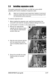
... later use . ASUS AP120-E1 user guide 2-17 To install an expansion card: 1. Make sure to both the motherboard and the components. Lay the system on its side on the slot. 5. Before installing the expansion card, read the documentation that you removed 5 earlier. Failure to do so may cause severe damage to unplug the power supply before installing or removing an expansion card(s). Align the card connector with it and make the necessary hardware settings for installation of expansion cards. Remove...
... later use . ASUS AP120-E1 user guide 2-17 To install an expansion card: 1. Make sure to both the motherboard and the components. Lay the system on its side on the slot. 5. Before installing the expansion card, read the documentation that you removed 5 earlier. Failure to do so may cause severe damage to unplug the power supply before installing or removing an expansion card(s). Align the card connector with it and make the necessary hardware settings for installation of expansion cards. Remove...
User Guide
Page 35
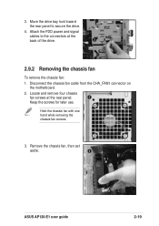
Move the drive bay lock toward the rear panel to the connectors at the rear panel. 2 Keep the screws for later use. Hold the chassis fan with one hand while removing the chassis fan screws. 3. Attach the FDD power and signal cables to secure the drive. 4. Locate and remove four chassis fan screws at the back of the drive. 3 2.9.2 Removing the chassis fan To remove the chassis fan: 1. Remove the chassis fan, then set aside. 3 ASUS AP120-E1 user guide 2-19 3. Disconnect the chassis fan cable from the CHA_FAN1 connector on the motherboard. 2.
Move the drive bay lock toward the rear panel to the connectors at the rear panel. 2 Keep the screws for later use. Hold the chassis fan with one hand while removing the chassis fan screws. 3. Attach the FDD power and signal cables to secure the drive. 4. Locate and remove four chassis fan screws at the back of the drive. 3 2.9.2 Removing the chassis fan To remove the chassis fan: 1. Remove the chassis fan, then set aside. 3 ASUS AP120-E1 user guide 2-19 3. Disconnect the chassis fan cable from the CHA_FAN1 connector on the motherboard. 2.
User Guide
Page 36
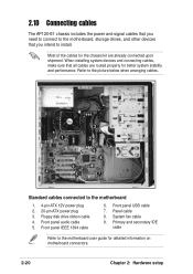
Front panel USB cable 7. System fan cable 9. Refer to the picture below when arranging cables. 3 1 2 9 8 6 4 5 7 Standard cables connected to the motherboard user guide for better system stability and performance. Floppy disk drive ribbon cable 4. Front panel audio cable 5. Primary and secondary IDE cable Refer to the motherboard 1. 4-pin ATX 12V power plug 2. 20-pin ATX power plug 3. Panel cable 8. When installing system devices and connecting cables, make sure that you need to connect to the motherboard, storage drives, and other devices that...
Front panel USB cable 7. System fan cable 9. Refer to the picture below when arranging cables. 3 1 2 9 8 6 4 5 7 Standard cables connected to the motherboard user guide for better system stability and performance. Floppy disk drive ribbon cable 4. Front panel audio cable 5. Primary and secondary IDE cable Refer to the motherboard 1. 4-pin ATX 12V power plug 2. 20-pin ATX power plug 3. Panel cable 8. When installing system devices and connecting cables, make sure that you need to connect to the motherboard, storage drives, and other devices that...
User Guide
Page 37
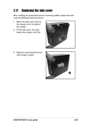
Slide the cover toward the chassis until it fits. 1 3. 2.11 Replacing the side cover After installing all components and re-connecting cables, replace the side cover by following these instructions. 1. Fit the side cover the cover toward the front until it snaps in place. 3 ASUS AP120-E1 user guide 2-21 Match the side cover hooks to the chassis rail on the side of the chassis. 2 2.
Slide the cover toward the chassis until it fits. 1 3. 2.11 Replacing the side cover After installing all components and re-connecting cables, replace the side cover by following these instructions. 1. Fit the side cover the cover toward the front until it snaps in place. 3 ASUS AP120-E1 user guide 2-21 Match the side cover hooks to the chassis rail on the side of the chassis. 2 2.
User Guide
Page 50
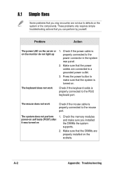
... sure that the DIMMs are properly installed on 1. These problems only requires simple troubleshooting actions that you installed the DIMMs the system supports. 2. The mouse does not work Check if the keyboard cable is turned on the monitor do not light up 1. Check the memory modules and make sure that the system is properly connected to the PS/2 keyboard port. A-2 Appendix: Troubleshooting Problem Action The power LED on the server or on . The...
... sure that the DIMMs are properly installed on 1. These problems only requires simple troubleshooting actions that you installed the DIMMs the system supports. 2. The mouse does not work Check if the keyboard cable is turned on the monitor do not light up 1. Check the memory modules and make sure that the system is properly connected to the PS/2 keyboard port. A-2 Appendix: Troubleshooting Problem Action The power LED on the server or on . The...
User Guide
Page 51
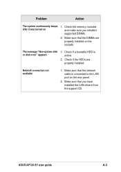
The message "Non-system disk or disk error" appears 1. Make sure that the DIMMs are properly installed. Make sure that you installed supported DIMMs. 2. Check if a bootable HDD is connected to the LAN port on 1. Check if the HDDs are properly installed on the sockets. Network connection not available 1. Check the memory modules and make sure you have installed the LAN drivers from the support CD. Problem Action The system continuously beeps after it was turned on the rear panel. 2. Make sure that the network cable is active. 2. ASUS AP120-E1 user guide A-3
The message "Non-system disk or disk error" appears 1. Make sure that the DIMMs are properly installed. Make sure that you installed supported DIMMs. 2. Check if a bootable HDD is connected to the LAN port on 1. Check if the HDDs are properly installed on the sockets. Network connection not available 1. Check the memory modules and make sure you have installed the LAN drivers from the support CD. Problem Action The system continuously beeps after it was turned on the rear panel. 2. Make sure that the network cable is active. 2. ASUS AP120-E1 user guide A-3


