AP110 User Manual
Page 3
... Panel Features 15 1.3 Rear Panel Features 16 1.4 Internal Features 17 Chapter 2: Hardware Setup 19 2.1 Remove the Front Cover 20 Unlock the Front Panel 20 Remove the Screws 20 Remove the Panel 20 2.2 Remove the Chassis Cover 21 Remove the Screws 21 Remove the Cover 21 2.3 Motherboard Placement 22 Placement Direction 22 Motherboard Screws 22 2.4 Install a CPU 23 CPU Socket Location 23 CPU Orientation 23 Unlock the CPU Socket 24 Insert the CPU 24 Secure the CPU 25 Connect the Fan Cable...
... Panel Features 15 1.3 Rear Panel Features 16 1.4 Internal Features 17 Chapter 2: Hardware Setup 19 2.1 Remove the Front Cover 20 Unlock the Front Panel 20 Remove the Screws 20 Remove the Panel 20 2.2 Remove the Chassis Cover 21 Remove the Screws 21 Remove the Cover 21 2.3 Motherboard Placement 22 Placement Direction 22 Motherboard Screws 22 2.4 Install a CPU 23 CPU Socket Location 23 CPU Orientation 23 Unlock the CPU Socket 24 Insert the CPU 24 Secure the CPU 25 Connect the Fan Cable...

AP110 User Manual
Page 4
... 2.5 Install System Memory 26 DIMM Sockets Location 26 Install a DIMM 26 2.6 Install a Hard Disk Drive 27 HDD Metal Cage 27 Remove the HDD Cage 27 Install the HDD 28 Replace the HDD Cage 28 Connect the Cables 29 IDE HDD Cabling 29 2.7 Replace the Covers 30 Re-install the Cover 30 Re-install the Panel 30 Chapter 3: Powering Up 31 3.1 Getting Started 32 Connect a Monitor 32 Connect the Power Cord 32 Power On 32 Check Power Status 32 Chapter 4: Hardware Options 33 4.1 IDE RAID Kit...
... 2.5 Install System Memory 26 DIMM Sockets Location 26 Install a DIMM 26 2.6 Install a Hard Disk Drive 27 HDD Metal Cage 27 Remove the HDD Cage 27 Install the HDD 28 Replace the HDD Cage 28 Connect the Cables 29 IDE HDD Cabling 29 2.7 Replace the Covers 30 Re-install the Cover 30 Re-install the Panel 30 Chapter 3: Powering Up 31 3.1 Getting Started 32 Connect a Monitor 32 Connect the Power Cord 32 Power On 32 Check Power Status 32 Chapter 4: Hardware Options 33 4.1 IDE RAID Kit...

AP110 User Manual
Page 8
... installing or removing signal cables, ensure that the power cables for the user's safety. If possible, disconnect all power cables from connectors, slots, sockets and circuitry. • Avoid dust, humidity, and temperature extremes. Use the power cable with the server package. • Before using the server, make sure all the manuals included with a properly grounded electrical outlet to fix it by certified or experienced engineers. • Before operating the server...
... installing or removing signal cables, ensure that the power cables for the user's safety. If possible, disconnect all power cables from connectors, slots, sockets and circuitry. • Avoid dust, humidity, and temperature extremes. Use the power cable with the server package. • Before using the server, make sure all the manuals included with a properly grounded electrical outlet to fix it by certified or experienced engineers. • Before operating the server...

AP110 User Manual
Page 9
This part includes the target audience, chapter description, and conventions used. It also lists other sources of this manual. AP110 Server User's Manual 9 About This Manual Introduction "About This Manual" introduces the contents of information that are not contained in this document.
This part includes the target audience, chapter description, and conventions used. It also lists other sources of this manual. AP110 Server User's Manual 9 About This Manual Introduction "About This Manual" introduces the contents of information that are not contained in this document.
AP110 User Manual
Page 10
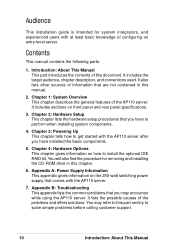
... panel and rear panel specifications. 3. Contents This manual contains the following parts: 1. Chapter 3: Powering Up This chapter tells how to solve simple problems before calling customer support. 10 Introduction: About This Manual You may encounter while using the AP110 server. Audience This installation guide is intended for removing and installing the CD-ROM drive in this part and try to get started with at least basic knowledge of configuring an entry-level server...
... panel and rear panel specifications. 3. Contents This manual contains the following parts: 1. Chapter 3: Powering Up This chapter tells how to solve simple problems before calling customer support. 10 Introduction: About This Manual You may encounter while using the AP110 server. Audience This installation guide is intended for removing and installing the CD-ROM drive in this part and try to get started with at least basic knowledge of configuring an entry-level server...
AP110 User Manual
Page 12
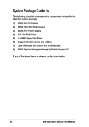
System Package Contents The following checklist enumerates the components included in the standard system package. 1) ASUS AS-15 Chassis 2) ASUS CUV-2LV Motherboard 3) 250W ATX Power Supply 4) 50X CD-ROM Drive 5) 1.44MB Floppy Disk Drive 6) Support CD with Drivers and Utilities 7) User's Manuals (for system and motherboard) 8) ASUS System Management Agent (ASMA) Support CD If any of the above items is missing, contact your dealer. 12 Introduction: About This Manual
System Package Contents The following checklist enumerates the components included in the standard system package. 1) ASUS AS-15 Chassis 2) ASUS CUV-2LV Motherboard 3) 250W ATX Power Supply 4) 50X CD-ROM Drive 5) 1.44MB Floppy Disk Drive 6) Support CD with Drivers and Utilities 7) User's Manuals (for system and motherboard) 8) ASUS System Management Agent (ASMA) Support CD If any of the above items is missing, contact your dealer. 12 Introduction: About This Manual
AP110 User Manual
Page 14
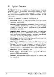
... voltage selector switch • Security: Equipped with 4MB video memory • Storage: Four external bays that accommodates the ASUS CUV-2LV motherboard. The server is a stylish tower chassis that support two optional 5.25-inch IDE hot-swap drives, one 50X CD-ROM, and 1.44MB floppy drive; 1.1 System Features The ASUS AP110 Server is powered by Intel® Pentium® III/Celeron™ processor, and supports the latest I /O integrated peripheral controller • LAN...
... voltage selector switch • Security: Equipped with 4MB video memory • Storage: Four external bays that accommodates the ASUS CUV-2LV motherboard. The server is a stylish tower chassis that support two optional 5.25-inch IDE hot-swap drives, one 50X CD-ROM, and 1.44MB floppy drive; 1.1 System Features The ASUS AP110 Server is powered by Intel® Pentium® III/Celeron™ processor, and supports the latest I /O integrated peripheral controller • LAN...

AP110 User Manual
Page 15
Chassis Keylock Front Panel Door Floppy Disk Drive Power LED IDE HDD LED Hot-Swap IDE Drives (optional) Power Button Reset Button CD-ROM Drive AP110 Server User's Manual 15 When the door is designed with a door on the upper part secured by a keylock. When locked, the door provides security to the hot-swap IDE drives and other internal components because neither the front panel nor the chassis cover cannot be removed. 1.2 Front Panel Features The AP110 front panel is open, you can easily access the hot-swap IDE drives (if available), floppy disk drive, and CD-ROM drive.
Chassis Keylock Front Panel Door Floppy Disk Drive Power LED IDE HDD LED Hot-Swap IDE Drives (optional) Power Button Reset Button CD-ROM Drive AP110 Server User's Manual 15 When the door is designed with a door on the upper part secured by a keylock. When locked, the door provides security to the hot-swap IDE drives and other internal components because neither the front panel nor the chassis cover cannot be removed. 1.2 Front Panel Features The AP110 front panel is open, you can easily access the hot-swap IDE drives (if available), floppy disk drive, and CD-ROM drive.
AP110 User Manual
Page 17
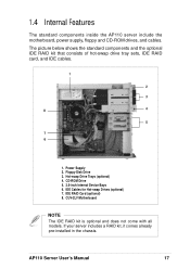
... Disk Drive 3. Hot-swap Drive Trays (optional) 4. If your server includes a RAID kit, it comes already pre-installed in the chassis. IDE Cables for Hot-swap Drives (optional) 7. AP110 Server User's Manual 17 CUV-2LV Motherboard NOTE The IDE RAID kit is optional and does not come with all models. CD-ROM Drive 5. 3.5-inch Internal Device Bays 6. Power Supply 2. IDE RAID Card (optional) 8. The picture below shows the standard components and the optional IDE RAID kit that consists of hot-swap drive...
... Disk Drive 3. Hot-swap Drive Trays (optional) 4. If your server includes a RAID kit, it comes already pre-installed in the chassis. IDE Cables for Hot-swap Drives (optional) 7. AP110 Server User's Manual 17 CUV-2LV Motherboard NOTE The IDE RAID kit is optional and does not come with all models. CD-ROM Drive 5. 3.5-inch Internal Device Bays 6. Power Supply 2. IDE RAID Card (optional) 8. The picture below shows the standard components and the optional IDE RAID kit that consists of hot-swap drive...
AP110 User Manual
Page 22
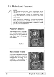
... external ports goes to the rear part of the AP110 server are already installed as indicated in the holes indicated by circles to secure the motherboard to Chapter 4 for detailed technical information about the motherboard. The edge with the motherboard. Rear Panel Motherboard Screws Place nine (9) screws in section "1.4 Internal Features". 2.3 Motherboard Placement NOTE The motherboard and other internal components of the chassis. Refer to the chassis. When removing the motherboard, you...
... external ports goes to the rear part of the AP110 server are already installed as indicated in the holes indicated by circles to secure the motherboard to Chapter 4 for detailed technical information about the motherboard. The edge with the motherboard. Rear Panel Motherboard Screws Place nine (9) screws in section "1.4 Internal Features". 2.3 Motherboard Placement NOTE The motherboard and other internal components of the chassis. Refer to the chassis. When removing the motherboard, you...
AP110 User Manual
Page 26
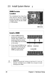
.... 2.5 Install System Memor y DIMM Sockets Location The motherboard has three Dual Inline Memory Module (DIMM) sockets that they fit in only one direction. DIMM Sockets Install a DIMM 1. DIMM Notch Socket Break Installed DIMM CAUTION DIMMs are keyed with notches so that support 3.3V SDRAM modules in 32, 64, 128, 256, 512MB, or 1GB densities. Firmly insert the DIMM into a socket to avoid damaging the DIMM. 26 Chapter 3: Hardware Setup Align a DIMM on...
.... 2.5 Install System Memor y DIMM Sockets Location The motherboard has three Dual Inline Memory Module (DIMM) sockets that they fit in only one direction. DIMM Sockets Install a DIMM 1. DIMM Notch Socket Break Installed DIMM CAUTION DIMMs are keyed with notches so that support 3.3V SDRAM modules in 32, 64, 128, 256, 512MB, or 1GB densities. Firmly insert the DIMM into a socket to avoid damaging the DIMM. 26 Chapter 3: Hardware Setup Align a DIMM on...

AP110 User Manual
Page 30
... the system key. 30 Chapter 2: Hardware Setup Open the panel door. 4. Lock the front panel with both hands until it fits in place. Re-install the Cover 1. Re-install the Panel 1. Secure the panel with the two screws that you are installing optional components such as the IDE RAID kit, proceed to the chassis. 2. 2.7 Replace the Covers NOTE If you removed earlier. 5. Slide the cover toward the rear panel until it...
... the system key. 30 Chapter 2: Hardware Setup Open the panel door. 4. Lock the front panel with both hands until it fits in place. Re-install the Cover 1. Re-install the Panel 1. Secure the panel with the two screws that you are installing optional components such as the IDE RAID kit, proceed to the chassis. 2. 2.7 Replace the Covers NOTE If you removed earlier. 5. Slide the cover toward the rear panel until it...

AP110 User Manual
Page 31
Chapter 3 This chapter tells how to get started with the AP110 server. Powering Up AP110 Server User's Manual 31 Powering up the server basically includes connecting the cables and turning power on.
Chapter 3 This chapter tells how to get started with the AP110 server. Powering Up AP110 Server User's Manual 31 Powering up the server basically includes connecting the cables and turning power on.

AP110 User Manual
Page 32
... monitor cable to the video port (blue port) on the rear panel. 3. Power Button Check Power Status After turning on the front panel. If it doesn't, check the power connection. 3.1 Getting Star ted Make sure that you have completed the basic system installations in Chapter 2, then follow these steps to the correct voltage in your area. 2. Adjust the voltage selector to start up . Power LED 32 Chapter 3: Powering Up Video Port Connect the Power Cord 1. Connect a power cord to a grounded Voltage...
... monitor cable to the video port (blue port) on the rear panel. 3. Power Button Check Power Status After turning on the front panel. If it doesn't, check the power connection. 3.1 Getting Star ted Make sure that you have completed the basic system installations in Chapter 2, then follow these steps to the correct voltage in your area. 2. Adjust the voltage selector to start up . Power LED 32 Chapter 3: Powering Up Video Port Connect the Power Cord 1. Connect a power cord to a grounded Voltage...
AP110 User Manual
Page 34
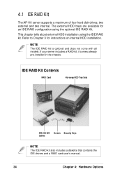
... chassis. IDE RAID Kit Contents RAID Card Hot-swap HDD Tray Sets ATA/100 IDE Screws Security Keys Cables NOTE The IDE RAID kit also includes a diskette that contains the IDE drivers and a RAID card user's manual. 34 Chapter 4: Hardware Options 4.1 IDE RAID Kit The AP110 server supports a maximum of four hard disk drives, two external and two internal. NOTE The IDE RAID kit is optional and does not come with all models. Refer to Chapter 3 for an IDE RAID configuration using...
... chassis. IDE RAID Kit Contents RAID Card Hot-swap HDD Tray Sets ATA/100 IDE Screws Security Keys Cables NOTE The IDE RAID kit also includes a diskette that contains the IDE drivers and a RAID card user's manual. 34 Chapter 4: Hardware Options 4.1 IDE RAID Kit The AP110 server supports a maximum of four hard disk drives, two external and two internal. NOTE The IDE RAID kit is optional and does not come with all models. Refer to Chapter 3 for an IDE RAID configuration using...

AP110 User Manual
Page 35
... HDD fan, an IDE connector (male), and a power connector. Power Cable IDE Cable Hot-swap HDD Tray with Cover AP110 Server User's Manual 35 The drive tray interior includes an IDE cable and a power cable. This connector matches the 64-pin female connector at the back of the hot-swap drive tray. 64-pin Male Connector The back of the tray frame is found on the rear of the frame. HDD Fan IDE Connector Power Connector Hot-swap...
... HDD fan, an IDE connector (male), and a power connector. Power Cable IDE Cable Hot-swap HDD Tray with Cover AP110 Server User's Manual 35 The drive tray interior includes an IDE cable and a power cable. This connector matches the 64-pin female connector at the back of the hot-swap drive tray. 64-pin Male Connector The back of the tray frame is found on the rear of the frame. HDD Fan IDE Connector Power Connector Hot-swap...

AP110 User Manual
Page 38
... drive tray into the tray until it fits in place. 6. Carefully place the drive into the bay until it is flushed to prevent unauthorized access. Do steps 1 to 7 to the rails at the back of the drive. 3. Secure the drive with the security key to the front panel. 7. Align the tray cover to install the Drive Trays other hot-swap drive. 38 Chapter 4: Hardware...
... drive tray into the tray until it fits in place. 6. Carefully place the drive into the bay until it is flushed to prevent unauthorized access. Do steps 1 to 7 to the rails at the back of the drive. 3. Secure the drive with the security key to the front panel. 7. Align the tray cover to install the Drive Trays other hot-swap drive. 38 Chapter 4: Hardware...

AP110 User Manual
Page 41
... chassis. 3. Carefully pull the drive out of the Motherboard Hot-swap HHD Trays and CD-ROM Drive Pulled Out AP110 Server User's Manual 41 Simply pull out the drive for either one of the motherboard, so you also have to remove and re-install the CD-ROM drive. You need to replace the drive 2. Top Right Corner of the chassis. 4.5 CD-ROM Drive The server comes with the motherboard. Disconnect the power and IDE cables...
... chassis. 3. Carefully pull the drive out of the Motherboard Hot-swap HHD Trays and CD-ROM Drive Pulled Out AP110 Server User's Manual 41 Simply pull out the drive for either one of the motherboard, so you also have to remove and re-install the CD-ROM drive. You need to replace the drive 2. Top Right Corner of the chassis. 4.5 CD-ROM Drive The server comes with the motherboard. Disconnect the power and IDE cables...

AP110 User Manual
Page 48
Problem Action The power LED on the system rear panel if properly connected. 3. Check the power cable connection on the server and/or the monitor do not light up The keyboard does not work The mouse does not work 1. Press the power button to make sure you installed the DIMMs the system supports. 2. Make sure that the DIMMs are properly installed on . These problems only requires simple troubleshooting actions that the power cables are connected to a grounded...
Problem Action The power LED on the system rear panel if properly connected. 3. Check the power cable connection on the server and/or the monitor do not light up The keyboard does not work The mouse does not work 1. Press the power button to make sure you installed the DIMMs the system supports. 2. Make sure that the DIMMs are properly installed on . These problems only requires simple troubleshooting actions that the power cables are connected to a grounded...
AP110 User Manual
Page 49
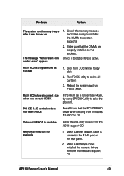
... the RAID set is only detected as 1024MB 1. AP110 Server User's Manual 49 RAID HDD is larger than 64GB, try using SPFDISK utility to delete all partition 3. Check if bootable HDD is connector the RJ-45 port on the rear panel. 2. Boot from the motherboard support CD. Problem Action The system continuously beeps after it was turned on the sockets. Make sure that the DIMMs are properly installed on The message "Non-system disk or disk error...
... the RAID set is only detected as 1024MB 1. AP110 Server User's Manual 49 RAID HDD is larger than 64GB, try using SPFDISK utility to delete all partition 3. Check if bootable HDD is connector the RJ-45 port on the rear panel. 2. Boot from the motherboard support CD. Problem Action The system continuously beeps after it was turned on the sockets. Make sure that the DIMMs are properly installed on The message "Non-system disk or disk error...


