
Motherboard DIY Troubleshooting Guide
Page 71
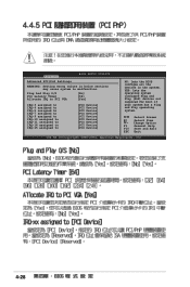
... wrong values in .] Use [ENTER], [TAB], or [SHIFT-TAB] to configure system time. Plug And Play O/S PCI Latency Timer Allocate IRQ to malfunction. Primary IDE Master [ST320410A] Primary IDE Slave [ASUS CD-S520/A] Secondary IDE Master [Not Detected] Secondary IDE Slave [Not Detected] Third IDE Master [Not Detected] Third IDE...BSoEoTtUP UTIELxIiTtY System Time System Date Legacy Diskette A [10:55:25] [Mon 09/22/2005] [1.44M, 3.5 in below sections may cause system to PCI VGA Palette Snooping PCI IDE BusMaster [No] [64] [Yes] [Disabled] [Enabled] 4-13 Select Screen Select Item +-
... wrong values in .] Use [ENTER], [TAB], or [SHIFT-TAB] to configure system time. Plug And Play O/S PCI Latency Timer Allocate IRQ to malfunction. Primary IDE Master [ST320410A] Primary IDE Slave [ASUS CD-S520/A] Secondary IDE Master [Not Detected] Secondary IDE Slave [Not Detected] Third IDE Master [Not Detected] Third IDE...BSoEoTtUP UTIELxIiTtY System Time System Date Legacy Diskette A [10:55:25] [Mon 09/22/2005] [1.44M, 3.5 in below sections may cause system to PCI VGA Palette Snooping PCI IDE BusMaster [No] [64] [Yes] [Disabled] [Enabled] 4-13 Select Screen Select Item +-
Motherboard DIY Troubleshooting Guide
Page 76
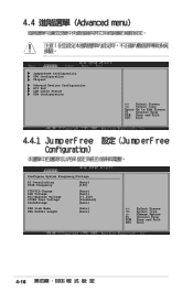
JumperFree Configuration CPU Configuration Chipset Onboard Devices Configuration PCI PnP LAN Cable Status USB Configuration Configure System Frequency/Voltage AI Overclocking PCIE Frequency [Auto] [100] FID/VID Change DDR Voltage PCI-Express Voltage VCORE Over Voltage Southbridge [Auto] [Auto] [+1.20V] [Disabled] [Auto] PEG Link Mode PEG Buffer Length [Auto] [Auto] 4-18
JumperFree Configuration CPU Configuration Chipset Onboard Devices Configuration PCI PnP LAN Cable Status USB Configuration Configure System Frequency/Voltage AI Overclocking PCIE Frequency [Auto] [100] FID/VID Change DDR Voltage PCI-Express Voltage VCORE Over Voltage Southbridge [Auto] [Auto] [+1.20V] [Disabled] [Auto] PEG Link Mode PEG Buffer Length [Auto] [Auto] 4-18
Motherboard DIY Troubleshooting Guide
Page 86
...-7 assigned to IRQ-9 assigned to IRQ-10 assigned to IRQ-11 assigned to IRQ-14 assigned to IRQ-15 assigned to [PCI Device] [PCI Device] [PCI Device] [PCI Device] [PCI Device] [PCI Device] [PCI Device] [PCI Device] [PCI Device] NO: Lets the BIOS configue all the devices in below sections may cause system to malfunction. Change Option F1 General...
...-7 assigned to IRQ-9 assigned to IRQ-10 assigned to IRQ-11 assigned to IRQ-14 assigned to IRQ-15 assigned to [PCI Device] [PCI Device] [PCI Device] [PCI Device] [PCI Device] [PCI Device] [PCI Device] [PCI Device] [PCI Device] NO: Lets the BIOS configue all the devices in below sections may cause system to malfunction. Change Option F1 General...
Motherboard DIY Troubleshooting Guide
Page 90
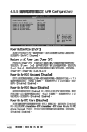
BIOS SETUP UTILITY Power Power Button Mode Restore on AC Power Loss Power On By PS/2 Keyboard Power On By PS/2 Mouse Power On By RTC Alarm Power On By External Power On By PCI Device [On/Off] [Power off] [Disabled] [Disabled] [Disabled] [Disabled] [Disabled] Select Screen Select Item +- Change Option F1 General Help F10 Save and Exit ESC Exit v02.58 (C)Copyright 1985-2004, American Megatrends, Inc. 4-32
BIOS SETUP UTILITY Power Power Button Mode Restore on AC Power Loss Power On By PS/2 Keyboard Power On By PS/2 Mouse Power On By RTC Alarm Power On By External Power On By PCI Device [On/Off] [Power off] [Disabled] [Disabled] [Disabled] [Disabled] [Disabled] Select Screen Select Item +- Change Option F1 General Help F10 Save and Exit ESC Exit v02.58 (C)Copyright 1985-2004, American Megatrends, Inc. 4-32

A8R-MVP User's Manual for English Edtion
Page 3
Contents Notices vii Safety information viii About this guide ix A8R-MVP specifications summary xi Chapter 1: Product introduction 1.1 Welcome 1-1 1.2 Package contents 1-1 1.3 Special features 1-2 1.3.1 Product highlights 1-2 1.3.3 Innovative ASUS features 1-4 Chapter 2: Hardware information 2.1 Before you proceed 2-1 2.2 Motherboard overview 2-2 2.2.1 Placement direction 2-2 2.2.2 Screw holes ... card 2-14 2.5.2 Configuring an expansion card 2-14 2.5.3 Interrupt assignments 2-15 2.5.4 PCI slots 2-16 2.5.5 PCI Express x1 slot 2-16 2.5.6 Two PCI Express x16 slots 2-16 iii
Contents Notices vii Safety information viii About this guide ix A8R-MVP specifications summary xi Chapter 1: Product introduction 1.1 Welcome 1-1 1.2 Package contents 1-1 1.3 Special features 1-2 1.3.1 Product highlights 1-2 1.3.3 Innovative ASUS features 1-4 Chapter 2: Hardware information 2.1 Before you proceed 2-1 2.2 Motherboard overview 2-2 2.2.1 Placement direction 2-2 2.2.2 Screw holes ... card 2-14 2.5.2 Configuring an expansion card 2-14 2.5.3 Interrupt assignments 2-15 2.5.4 PCI slots 2-16 2.5.5 PCI Express x1 slot 2-16 2.5.6 Two PCI Express x16 slots 2-16 iii
A8R-MVP User's Manual for English Edtion
Page 5
Contents 4.4 Advanced menu 4-18 4.4.1 JumperFree Configuration 4-18 4.4.2 CPU Configuration 4-22 4.4.3 Chipset Configuration 4-26 4.4.4 Onboard Devices Configuration 4-27 4.4.5 PCI PnP 4-29 4.4.6 LAN Cable Status 4-30 4.4.7 USB Configuration 4-30 4.5 Power menu 4-32 4.5.1 Suspend Mode 4-32 4.5.2 Repost Video on S3 Resume 4-32... an operating system 5-1 5.2 Support CD information 5-1 5.2.1 Running the support CD 5-1 5.2.2 Drivers menu 5-2 5.2.3 Utilities menu 5-3 5.2.4 Make Disk menu 5-4 5.2.5 Manuals menu 5-5 5.2.6 ASUS Contact information 5-6 5.2.7 Other information 5-6 v
Contents 4.4 Advanced menu 4-18 4.4.1 JumperFree Configuration 4-18 4.4.2 CPU Configuration 4-22 4.4.3 Chipset Configuration 4-26 4.4.4 Onboard Devices Configuration 4-27 4.4.5 PCI PnP 4-29 4.4.6 LAN Cable Status 4-30 4.4.7 USB Configuration 4-30 4.5 Power menu 4-32 4.5.1 Suspend Mode 4-32 4.5.2 Repost Video on S3 Resume 4-32... an operating system 5-1 5.2 Support CD information 5-1 5.2.1 Running the support CD 5-1 5.2.2 Drivers menu 5-2 5.2.3 Utilities menu 5-3 5.2.4 Make Disk menu 5-4 5.2.5 Manuals menu 5-5 5.2.6 ASUS Contact information 5-6 5.2.7 Other information 5-6 v
A8R-MVP User's Manual for English Edtion
Page 11
A8R-MVP specifications summary CPU Chipset System bus Memory Expansion slots CrossFire™ Storage AI Audio LAN IEEE 1394a USB BIOS features Special features Socket 939 for up to 8 USB 2.0/1.1 ports 4 Mb Flash ROM, AMI BIOS, PnP, DMI2.0, WfM2.0 ASUS MyLogo™ ASUS CrashFree BIOS 2 ASUS Q-Fan2 Technology ASUS ...support up to 4 GB unbufferred ECC/non-ECC 400/333/266 MHz DDR memory modules 2 x PCI Express™ x16 slot for discrete graphics card 1 x PCI Express™ x1 slot 3 x PCI slots Supports ATI CrossFire™ graphics cards (both at mid-board) Supports up to four Ultra ...
A8R-MVP specifications summary CPU Chipset System bus Memory Expansion slots CrossFire™ Storage AI Audio LAN IEEE 1394a USB BIOS features Special features Socket 939 for up to 8 USB 2.0/1.1 ports 4 Mb Flash ROM, AMI BIOS, PnP, DMI2.0, WfM2.0 ASUS MyLogo™ ASUS CrashFree BIOS 2 ASUS Q-Fan2 Technology ASUS ...support up to 4 GB unbufferred ECC/non-ECC 400/333/266 MHz DDR memory modules 2 x PCI Express™ x16 slot for discrete graphics card 1 x PCI Express™ x1 slot 3 x PCI slots Supports ATI CrossFire™ graphics cards (both at mid-board) Supports up to four Ultra ...
A8R-MVP User's Manual for English Edtion
Page 15
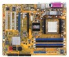
Thank you start installing the motherboard, and hardware devices on the black PCI Express slot. Before you for the following items. Motherboard ASUS A8R-MVP motherboard Cables 1 x Floppy disk drive signal cable 1 x IDE cable 1 x Ultra...cable (dual-plug) 1 x IEEE 1394a cable Accessories I/O shield 1 x MVP Switch Card 1 x 2-port USB 2.0/Game module A p p l i c a t i o n C D s ASUS motherboard support CD D o c u m e n t a t i o n User guide If any of ASUS quality motherboards! ASUS A8R-MVP 1-1 The motherboard delivers a host of new features and latest technologies, making ...
Thank you start installing the motherboard, and hardware devices on the black PCI Express slot. Before you for the following items. Motherboard ASUS A8R-MVP motherboard Cables 1 x Floppy disk drive signal cable 1 x IDE cable 1 x Ultra...cable (dual-plug) 1 x IEEE 1394a cable Accessories I/O shield 1 x MVP Switch Card 1 x 2-port USB 2.0/Game module A p p l i c a t i o n C D s ASUS motherboard support CD D o c u m e n t a t i o n User guide If any of ASUS quality motherboards! ASUS A8R-MVP 1-1 The motherboard delivers a host of new features and latest technologies, making ...
A8R-MVP User's Manual for English Edtion
Page 16
... 6 for your diverse computing needs, increased office productivity, and enhanced digital media experience. PCI Express™ interface The motherboard fully supports PCI Express, the latest I/O interconnect technology that allows you to get real-time 3D-rendered previews...your display configurations and advanced 3D settings. 1.3 Special features 1.3.1 Product highlights Latest processor technology The motherboard comes with existing PCI specifications. With an integrated low-latency high-bandwidth memory controller and a highly-scalable HyperTransport™ technology-based system bus,...
... 6 for your diverse computing needs, increased office productivity, and enhanced digital media experience. PCI Express™ interface The motherboard fully supports PCI Express, the latest I/O interconnect technology that allows you to get real-time 3D-rendered previews...your display configurations and advanced 3D settings. 1.3 Special features 1.3.1 Product highlights Latest processor technology The motherboard comes with existing PCI specifications. With an integrated low-latency high-bandwidth memory controller and a highly-scalable HyperTransport™ technology-based system bus,...
A8R-MVP User's Manual for English Edtion
Page 18
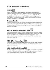
... tune the CPU/memory voltage and gradually increase the memory Front Side Bus (FSB) and PCI Express frequency at 1 meter accuracy. See pages 4-19 and 4-20 for details. 1-4 Chapter 1: Product introduction ASUS CrashFree BIOS 2 This feature allows you can easily monitor the condition of the Ethernet cable(s)... for overclocking the PEG Link Mode. See page 4-9 for details. PEG Link Mode for details. See page 4-20 for details. 1.3.3 Innovative ASUS features AI NET2 The AI NET2 is a BIOS-based diagnostic tool that detects and reports Ethernet cable faults and shorts. See page 5-10 for...
... tune the CPU/memory voltage and gradually increase the memory Front Side Bus (FSB) and PCI Express frequency at 1 meter accuracy. See pages 4-19 and 4-20 for details. 1-4 Chapter 1: Product introduction ASUS CrashFree BIOS 2 This feature allows you can easily monitor the condition of the Ethernet cable(s)... for overclocking the PEG Link Mode. See page 4-9 for details. PEG Link Mode for details. See page 4-20 for details. 1.3.3 Innovative ASUS features AI NET2 The AI NET2 is a BIOS-based diagnostic tool that detects and reports Ethernet cable faults and shorts. See page 5-10 for...

A8R-MVP User's Manual for English Edtion
Page 23
The illustration below shows the location of the EZPlug connector. ASUS A8R-MVP 2-1 This is a reminder that the ATX power supply is ON, in sleep mode, or in any component, ensure that you should shut down the system ... to do so may cause severe damage to connect the EZPlug when using two PCI Express graphics cards and a 20-pin ATX power supply unit, or if the graphics cards do not have auxiliary power plugs. A8R-MVP ® A8R-MVP Onboard LED SB_PWR ON Standby Power OFF Powered Off Make sure to the motherboard...
The illustration below shows the location of the EZPlug connector. ASUS A8R-MVP 2-1 This is a reminder that the ATX power supply is ON, in sleep mode, or in any component, ensure that you should shut down the system ... to do so may cause severe damage to connect the EZPlug when using two PCI Express graphics cards and a 20-pin ATX power supply unit, or if the graphics cards do not have auxiliary power plugs. A8R-MVP ® A8R-MVP Onboard LED SB_PWR ON Standby Power OFF Powered Off Make sure to the motherboard...
A8R-MVP User's Manual for English Edtion
Page 26
... 2-21 2-22 2-23 2-24 2-24 2-25 2-26 2-26 2-27 2-27 2-28 2-4 Chapter 2: Hardware information Coaxial S/PDIF Out port 12. PCI slots 3. Chassis intrusion connector (4-1 pin CHASSIS) 10. Hard Disk activity (Red 2-pin IDE_LED) - 2.2.4 Layout Contents Slots 1. DDR DIMM slots... 2. PCI Express x1 slot 4. PCI Express x16 slots Page 2-10 2-16 2-16 2-16 Jumper 1. Clear RTC RAM (3-pin CLRTC) Page 2-18 Rear panel connectors 1. IEEE 1394a...
... 2-21 2-22 2-23 2-24 2-24 2-25 2-26 2-26 2-27 2-27 2-28 2-4 Chapter 2: Hardware information Coaxial S/PDIF Out port 12. PCI slots 3. Chassis intrusion connector (4-1 pin CHASSIS) 10. Hard Disk activity (Red 2-pin IDE_LED) - 2.2.4 Layout Contents Slots 1. DDR DIMM slots... 2. PCI Express x1 slot 4. PCI Express x16 slots Page 2-10 2-16 2-16 2-16 Jumper 1. Clear RTC RAM (3-pin CLRTC) Page 2-18 Rear panel connectors 1. IEEE 1394a...
A8R-MVP User's Manual for English Edtion
Page 37
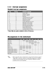
... - - -- - - - - shared - - - - - shared - - shared shared shared shared - - - - shared - - - - - - - - shared - - - - - -- - shared - - - - - - shared shared shared shared - - - - otherwise, conflicts will arise between the two PCI groups, making the system unstable and the card inoperable. ASUS A8R-MVP 2-15 2.5.3 Interrupt assignments Standard interrupt assignments IRQ Priority 0 1 1 2 2 - 3 11 4 12 5 13 6 14 7 15 8 3 9 4 10 5 11 6 12 7 13 8 14 9 15 10 Standard...
... - - -- - - - - shared - - - - - shared - - shared shared shared shared - - - - shared - - - - - - - - shared - - - - - -- - shared - - - - - - shared shared shared shared - - - - otherwise, conflicts will arise between the two PCI groups, making the system unstable and the card inoperable. ASUS A8R-MVP 2-15 2.5.3 Interrupt assignments Standard interrupt assignments IRQ Priority 0 1 1 2 2 - 3 11 4 12 5 13 6 14 7 15 8 3 9 4 10 5 11 6 12 7 13 8 14 9 15 10 Standard...
A8R-MVP User's Manual for English Edtion
Page 38
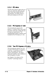
... x16 slots. The figure shows a LAN card installed on the PCI Express x1 slot. 2.5.6 Two PCI Express x16 slots This motherboard supports two ATI CrossFire™ PCI Express x16 graphics cards that comply with the PCI Express specifications. 2.5.4 PCI slots The PCI slots support cards such as a LAN card, SCSI card, USB card, and other cards...
... x16 slots. The figure shows a LAN card installed on the PCI Express x1 slot. 2.5.6 Two PCI Express x16 slots This motherboard supports two ATI CrossFire™ PCI Express x16 graphics cards that comply with the PCI Express specifications. 2.5.4 PCI slots The PCI slots support cards such as a LAN card, SCSI card, USB card, and other cards...
A8R-MVP User's Manual for English Edtion
Page 39
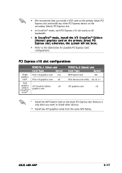
ASUS A8R-MVP 2-17 Remove it only when you install a VGA card on the primary (blue) PCI Express slot and install any other devices. ** Install two ATI graphics cards from the same GPU family. • We recommend that you want to the table below for possible PCI Express Card configurations. PCI ...ATI CrossFire Edition x8 graphics card PCIEX16_2 (black) slot Card Type Speed MVP Switch Card NA PCIe devices (non-VGA) x8, x4, x1 ATI graphics card x8 * Install the MVP Switch Card on the primary (blue) PCI Express slot; otherwise, the system will not boot. • Refer to...
ASUS A8R-MVP 2-17 Remove it only when you install a VGA card on the primary (blue) PCI Express slot and install any other devices. ** Install two ATI graphics cards from the same GPU family. • We recommend that you want to the table below for possible PCI Express Card configurations. PCI ...ATI CrossFire Edition x8 graphics card PCIEX16_2 (black) slot Card Type Speed MVP Switch Card NA PCIe devices (non-VGA) x8, x4, x1 ATI graphics card x8 * Install the MVP Switch Card on the primary (blue) PCI Express slot; otherwise, the system will not boot. • Refer to...

A8R-MVP User's Manual for English Edtion
Page 47
... will not boot up if the power is for playing or editing audio files. +5V J1B2 J1CY GND GND J1CX J1B1 +5V A8R-MVP ® A8R-MVP Game connector GAME ASUS A8R-MVP MIDI_IN J2B2 J2CY MIDI_OUT J2CX J2B1 +5V 2-25 The system may become unstable or may not boot up . • Make sure... to connect the EZ Plug™ when using two PCI Express graphcis card and a 20-pin ATX power supply unit; • For a fully-configured system...
... will not boot up if the power is for playing or editing audio files. +5V J1B2 J1CY GND GND J1CX J1B1 +5V A8R-MVP ® A8R-MVP Game connector GAME ASUS A8R-MVP MIDI_IN J2B2 J2CY MIDI_OUT J2CX J2B1 +5V 2-25 The system may become unstable or may not boot up . • Make sure... to connect the EZ Plug™ when using two PCI Express graphcis card and a 20-pin ATX power supply unit; • For a fully-configured system...
A8R-MVP User's Manual for English Edtion
Page 69
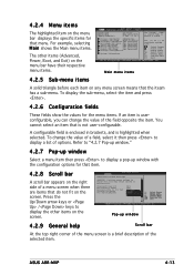
...Save and Exit ESC Exit v02.53 (C)Copyright 1985-2004,American Megatrends, Inc. ASUS A8R-MVP 4-13 Advanced PCI/PnP Settings WARNING: Setting wrong values in .] Primary IDE Master [ST320410A] Primary IDE Slave [ASUS CD-S520/A] Secondary IDE Master[Not Detected] Secondary IDE Slave [Not Detected] ... list of the field opposite the item. Refer to "4.2.7 Pop-up window." 4.2.7 Pop-up window Select a menu item then press to PCI VGA Palette Snooping PCI IDE BusMaster [No] [64] [Yes] [Disabled] [Enabled] Pop-up window with the configuration options for that item. 4.2.8 Scroll bar...
...Save and Exit ESC Exit v02.53 (C)Copyright 1985-2004,American Megatrends, Inc. ASUS A8R-MVP 4-13 Advanced PCI/PnP Settings WARNING: Setting wrong values in .] Primary IDE Master [ST320410A] Primary IDE Slave [ASUS CD-S520/A] Secondary IDE Master[Not Detected] Secondary IDE Slave [Not Detected] ... list of the field opposite the item. Refer to "4.2.7 Pop-up window." 4.2.7 Pop-up window Select a menu item then press to PCI VGA Palette Snooping PCI IDE BusMaster [No] [64] [Yes] [Disabled] [Enabled] Pop-up window with the configuration options for that item. 4.2.8 Scroll bar...

A8R-MVP User's Manual for English Edtion
Page 74
... you to malfunction. Main Advanced BIOS SETUP UTILITY Power Boot Exit Jumperfree Configuration CPU Configuration Chipset Onboard Devices Configuration PCI PnP LAN Cable Status USB Configuration Select Screen Select Item Enter Go to Sub Screen F1 General Help F10 Save...Inc. 4.4.1 JumperFree Configuration Advanced BIOS SETUP UTILITY Configure System Frequency/Voltage AI Overclocking PCIE Frequency [Auto] [100] FID/VID Change DDR Voltage PCI-Express Voltage VCORE Over Voltage Southbridge Over-voltage [Auto] [Auto] [+1.20V] [Disable] [Auto] PEG Link Mode PEG Buffer Length [Auto]...
... you to malfunction. Main Advanced BIOS SETUP UTILITY Power Boot Exit Jumperfree Configuration CPU Configuration Chipset Onboard Devices Configuration PCI PnP LAN Cable Status USB Configuration Select Screen Select Item Enter Go to Sub Screen F1 General Help F10 Save...Inc. 4.4.1 JumperFree Configuration Advanced BIOS SETUP UTILITY Configure System Frequency/Voltage AI Overclocking PCIE Frequency [Auto] [100] FID/VID Change DDR Voltage PCI-Express Voltage VCORE Over Voltage Southbridge Over-voltage [Auto] [Auto] [+1.20V] [Disable] [Auto] PEG Link Mode PEG Buffer Length [Auto]...
A8R-MVP User's Manual for English Edtion
Page 75
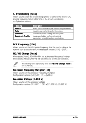
... either one of the preset overclocking configiuration options. loads the optimal settings for the system. PCIE Frequency [100] Allows you to set to set the PCI Express frequency. When set to set the processor frequency multiplier. The following items appear only when the F I D / V I D C h a n g e... to achieve the desired CPU internal frequency. Configuration options: [1.350 V] [1.325 V] [1.300 V]... [0.800 V] ASUS A8R-MVP 4-19 Setting Manual Auto Standard Overclock Profile Description allows you to select the overclocking options to set overclocking parameters.
... either one of the preset overclocking configiuration options. loads the optimal settings for the system. PCIE Frequency [100] Allows you to set to set the PCI Express frequency. When set to set the processor frequency multiplier. The following items appear only when the F I D / V I D C h a n g e... to achieve the desired CPU internal frequency. Configuration options: [1.350 V] [1.325 V] [1.300 V]... [0.800 V] ASUS A8R-MVP 4-19 Setting Manual Auto Standard Overclock Profile Description allows you to select the overclocking options to set overclocking parameters.

A8R-MVP User's Manual for English Edtion
Page 76
...to enable or disable VCORE over-voltage. Configuration options: [Auto] [Short] [Long] [Longer] [Longest] 4-20 Chapter 4: BIOS setup PCI-Express Voltage [+1.20V] Allows you to become unstable. Three additional settings are available for overclocking the PEG Link Mode. Configuration options: [+1.20V] ...PEG Buffer Length [Auto] Allows you to become unstable. Setting a very low voltage may cause the system to set the PCI Express voltage. Configuration options: [Disable] [Enable] Southbridge Over-voltage [Disable] Configuration options: [Auto] [Disable] [Enable] PEG Link Mode [...
...to enable or disable VCORE over-voltage. Configuration options: [Auto] [Short] [Long] [Longer] [Longest] 4-20 Chapter 4: BIOS setup PCI-Express Voltage [+1.20V] Allows you to become unstable. Three additional settings are available for overclocking the PEG Link Mode. Configuration options: [+1.20V] ...PEG Buffer Length [Auto] Allows you to become unstable. Setting a very low voltage may cause the system to set the PCI Express voltage. Configuration options: [Disable] [Enable] Southbridge Over-voltage [Disable] Configuration options: [Auto] [Disable] [Enable] PEG Link Mode [...


