
A8N5X User's Manual for English Edition
Page 1
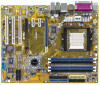
A8N5X Motherboard
A8N5X Motherboard

A8N5X User's Manual for English Edition
Page 3
... ix Where to find more information ix Conventions used in this guide x Typography x A8N5X specifications summary xi Chapter 1: Product introduction 1.1 Welcome 1-2 1.2 Package contents 1-2 1.3 Special features 1-3 1.3.1 Product highlights 1-3 1.3.2 ASUS Proactive features 1-5 1.3.3 Innovative ASUS features 1-6 1.4 Before you proceed 1-7 1.5 Motherboard overview 1-8 1.5.1 Placement direction 1-8 1.5.2 Screw holes 1-8 1.5.3 Motherboard layout 1-9 1.6 Central Processing Unit (CPU 1-10 1.6.1 Overview 1-10 1.6.2 Installling the CPU 1-10...
... ix Where to find more information ix Conventions used in this guide x Typography x A8N5X specifications summary xi Chapter 1: Product introduction 1.1 Welcome 1-2 1.2 Package contents 1-2 1.3 Special features 1-3 1.3.1 Product highlights 1-3 1.3.2 ASUS Proactive features 1-5 1.3.3 Innovative ASUS features 1-6 1.4 Before you proceed 1-7 1.5 Motherboard overview 1-8 1.5.1 Placement direction 1-8 1.5.2 Screw holes 1-8 1.5.3 Motherboard layout 1-9 1.6 Central Processing Unit (CPU 1-10 1.6.1 Overview 1-10 1.6.2 Installling the CPU 1-10...

A8N5X User's Manual for English Edition
Page 8
...cables are unplugged. • Seek professional assistance before you add a device. • Before connecting or removing signal cables from the motherboard, ensure that came with the product, contact a qualified service technician or your retailer. If you are not sure about the voltage ... staples away from connectors, slots, sockets and circuitry. • Avoid dust, humidity, and temperature extremes. Operation safety • Before installing the motherboard and adding devices on a stable surface. • If you detect any area where it may become wet. • Place the product on...
...cables are unplugged. • Seek professional assistance before you add a device. • Before connecting or removing signal cables from the motherboard, ensure that came with the product, contact a qualified service technician or your retailer. If you are not sure about the voltage ... staples away from connectors, slots, sockets and circuitry. • Avoid dust, humidity, and temperature extremes. Operation safety • Before installing the motherboard and adding devices on a stable surface. • If you detect any area where it may become wet. • Place the product on...

A8N5X User's Manual for English Edition
Page 9
...lists the hardware setup procedures that you need when installing and configuring the motherboard. Detailed descriptions of the BIOS parameters are not part of the jumpers and connectors on ASUS hardware and software products. Refer to change system settings through the BIOS ...Where to find more information Refer to perform when installing system components. ASUS websites The ASUS website provides updated information on the motherboard. • Chapter 2: BIOS setup This chapter tells how to the ASUS contact information. 2. It includes description of the standard package. About ...
...lists the hardware setup procedures that you need when installing and configuring the motherboard. Detailed descriptions of the BIOS parameters are not part of the jumpers and connectors on ASUS hardware and software products. Refer to change system settings through the BIOS ...Where to find more information Refer to perform when installing system components. ASUS websites The ASUS website provides updated information on the motherboard. • Chapter 2: BIOS setup This chapter tells how to the ASUS contact information. 2. It includes description of the standard package. About ...
A8N5X User's Manual for English Edition
Page 15
This chapter describes the motherboard features and the new technologies it supports. 1Product introduction ASUS A8N5X 1-1
This chapter describes the motherboard features and the new technologies it supports. 1Product introduction ASUS A8N5X 1-1
A8N5X User's Manual for English Edition
Page 16
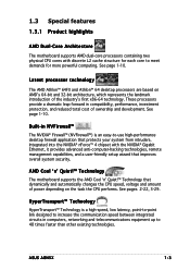
.... Motherboard ASUS A8N5X motherboard I/O modules USB 2.0 2-port module Cables 2 x Serial ATA signal cables 1 x Serial ATA power cables (dual plugs) Ultra DMA/133 cable 40-conductor IDE cable Floppy disk drive cable Accessories I/O shield A p p l i c a t i o n C D s ASUS motherboard support CD D o c u m e n t a t i o n User guide If any of the above items is damaged or missing, contact your motherboard package for buying an ASUS® A8N5X motherboard...
.... Motherboard ASUS A8N5X motherboard I/O modules USB 2.0 2-port module Cables 2 x Serial ATA signal cables 1 x Serial ATA power cables (dual plugs) Ultra DMA/133 cable 40-conductor IDE cable Floppy disk drive cable Accessories I/O shield A p p l i c a t i o n C D s ASUS motherboard support CD D o c u m e n t a t i o n User guide If any of the above items is damaged or missing, contact your motherboard package for buying an ASUS® A8N5X motherboard...
A8N5X User's Manual for English Edition
Page 17
AMD Cool 'n' Quiet!™ Technology The motherboard supports the AMD Cool 'n' Quiet!™ Technology that dynamically and automatically changes the CPU speed, voltage and amount of the industry's first x86-64 technology. ASUS A8N5X 1-3 HyperTransport™ Technology HyperTransport™ Technology is a high...task the CPU performs. See pages 2-22, 3-29. 1.3 Special features 1.3.1 Product highlights AMD Dual-Core Architecture The motherboard supports AMD dual-core processors containing two physical CPU cores with the NVIDIA® Gigabit Ethernet, it provides advanced anti-computer...
AMD Cool 'n' Quiet!™ Technology The motherboard supports the AMD Cool 'n' Quiet!™ Technology that dynamically and automatically changes the CPU speed, voltage and amount of the industry's first x86-64 technology. ASUS A8N5X 1-3 HyperTransport™ Technology HyperTransport™ Technology is a high...task the CPU performs. See pages 2-22, 3-29. 1.3 Special features 1.3.1 Product highlights AMD Dual-Core Architecture The motherboard supports AMD dual-core processors containing two physical CPU cores with the NVIDIA® Gigabit Ethernet, it provides advanced anti-computer...

A8N5X User's Manual for English Edition
Page 18
...interface is backward compatible with existing PCI specifications. USB 2.0 is software compatible with USB 1.1. PCI Express™ interface The motherboard fully supports PCI Express, the latest I/O interconnect technology that speeds up to powerful audio and speaker systems. See page 1-...lower pin count, and reduced voltage requirement. See page 1-18 for details. 1-4 Chapter 1: Product introduction Serial ATA technology The motherboard supports the next-generation Serial ATA technology through the S/PDIF interfaces on USB 2.0. See page 3-21 for the latest 3D graphics,...
...interface is backward compatible with existing PCI specifications. USB 2.0 is software compatible with USB 1.1. PCI Express™ interface The motherboard fully supports PCI Express, the latest I/O interconnect technology that speeds up to powerful audio and speaker systems. See page 1-...lower pin count, and reduced voltage requirement. See page 1-18 for details. 1-4 Chapter 1: Product introduction Serial ATA technology The motherboard supports the next-generation Serial ATA technology through the S/PDIF interfaces on USB 2.0. See page 3-21 for the latest 3D graphics,...
A8N5X User's Manual for English Edition
Page 19
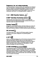
...S/PDIF out support, interrupt capability and includes the Realtek® proprietary UAJ® (Universal Audio Jack) technology. AI Audio technology The motherboard supports 8-channel audio through the onboard ALC850 CODEC with 16-bit DAC, a stereo 16-bit ADC, and an AC97 2.3 compatible multi...for critical components. The system fan rotations per minute (RPM) is monitored for details. See page 2-28 for timely failure detection. ASUS A8N5X 1-5 The ASIC monitors the voltage levels to ensure stable supply of the Ethernet cable(s) connected to your system configuration for details. ...
...S/PDIF out support, interrupt capability and includes the Realtek® proprietary UAJ® (Universal Audio Jack) technology. AI Audio technology The motherboard supports 8-channel audio through the onboard ALC850 CODEC with 16-bit DAC, a stereo 16-bit ADC, and an AC97 2.3 compatible multi...for critical components. The system fan rotations per minute (RPM) is monitored for details. See page 2-28 for timely failure detection. ASUS A8N5X 1-5 The ASIC monitors the voltage levels to ensure stable supply of the Ethernet cable(s) connected to your system configuration for details. ...

A8N5X User's Manual for English Edition
Page 20
... you to playback audio files even without booting the system to ensure quiet, cool, and efficient operation. ASUS MyLogo2™ This new feature present in the motherboard allows you to personalize and add style to restore the original BIOS data from the available options. See ...page 2-16 for details. Just press the ASUS Instant Music Lite special function keys and enjoy the music! 1.3.3 Innovative ASUS features CrashFree BIOS 2 ...
... you to playback audio files even without booting the system to ensure quiet, cool, and efficient operation. ASUS MyLogo2™ This new feature present in the motherboard allows you to personalize and add style to restore the original BIOS data from the available options. See ...page 2-16 for details. Just press the ASUS Instant Music Lite special function keys and enjoy the music! 1.3.3 Innovative ASUS features CrashFree BIOS 2 ...
A8N5X User's Manual for English Edition
Page 21
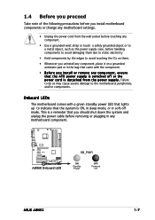
Failure to do so may cause severe damage to the motherboard, peripherals, and/or components. A8N5X ® A8N5X Onboard LED SB_PWR ON Standby Power OFF Powered Off ASUS A8N5X 1-7 This is a reminder that you should shut down the system and unplug the power cable before handling ... that the system is ON, in sleep mode, or in soft-off or the p o w e r c o r d i s d e t a c h e d f r o m t h e p o w e r s u p p l y . Onboard LEDs The motherboard comes with the component. • Before you install or remove any component, ensure that the ATX power supply is switched off mode.
Failure to do so may cause severe damage to the motherboard, peripherals, and/or components. A8N5X ® A8N5X Onboard LED SB_PWR ON Standby Power OFF Powered Off ASUS A8N5X 1-7 This is a reminder that you should shut down the system and unplug the power cable before handling ... that the system is ON, in sleep mode, or in soft-off or the p o w e r c o r d i s d e t a c h e d f r o m t h e p o w e r s u p p l y . Onboard LEDs The motherboard comes with the component. • Before you install or remove any component, ensure that the ATX power supply is switched off mode.
A8N5X User's Manual for English Edition
Page 22
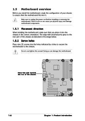
Do not overtighten the screws! Doing so can cause you physical injury and damage motherboard components. 1.5.1 Placement direction When installing the motherboard, make sure that you install the motherboard, study the configuration of the chassis A8N5X 1-8 Chapter 1: Product introduction The edge with external ports goes to the rear part of the chassis as indicated in...
Do not overtighten the screws! Doing so can cause you physical injury and damage motherboard components. 1.5.1 Placement direction When installing the motherboard, make sure that you install the motherboard, study the configuration of the chassis A8N5X 1-8 Chapter 1: Product introduction The edge with external ports goes to the rear part of the chassis as indicated in...
A8N5X User's Manual for English Edition
Page 23
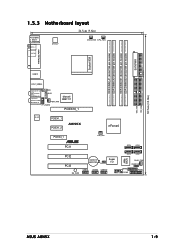
EATXPWR FLOPPY SEC_IDE PRI_IDE 30.5cm (12.0in) 1.5.3 Motherboard layout 24.5cm (9.6in) PS/2KBMS T: Mouse B: Keyboard SPDIF_O ATX12V CHA2_FAN CPU_FAN SPDIF_O2 DDR DIMM_A1 (64 bit,184-pin module) DDR DIMM_A2 (64 bit,184-...: Side Speaker Out Below: Center/Subwoofer CD AUX Top:Line In Center:Line Out Bottom:Mic In PWR_FAN FP_AUDIO Marvell 88E1111 PCIEX16_1 ACL850 PCIEX1_1 PCIEX1_2 A8N5X nForce4 PCIEX4_1 ® PCI1 CHIP_FAN PCI2 PCI3 SB_PWR CR2032 3V Lithium Cell CMOS Power CLRTC Super I/O USB78 USB56 USB910 SATA4 SATA3 SATA2 SATA1 4Mb BIOS...
EATXPWR FLOPPY SEC_IDE PRI_IDE 30.5cm (12.0in) 1.5.3 Motherboard layout 24.5cm (9.6in) PS/2KBMS T: Mouse B: Keyboard SPDIF_O ATX12V CHA2_FAN CPU_FAN SPDIF_O2 DDR DIMM_A1 (64 bit,184-pin module) DDR DIMM_A2 (64 bit,184-...: Side Speaker Out Below: Center/Subwoofer CD AUX Top:Line In Center:Line Out Bottom:Mic In PWR_FAN FP_AUDIO Marvell 88E1111 PCIEX16_1 ACL850 PCIEX1_1 PCIEX1_2 A8N5X nForce4 PCIEX4_1 ® PCI1 CHIP_FAN PCI2 PCI3 SB_PWR CR2032 3V Lithium Cell CMOS Power CLRTC Super I/O USB78 USB56 USB910 SATA4 SATA3 SATA2 SATA1 4Mb BIOS...

A8N5X User's Manual for English Edition
Page 24
Locate the CPU socket on your left. 2. 1.6 Central Processing Unit (CPU) 1.6.1 Overview The motherboard comes with only 32-bit or 64-bit wide data paths. The 128-bit-wide data paths of the marked corner (with gold triangle) on ... a 90°-100° angle. 1-10 Make sure that the socket box is facing towards you and the load lever is on the motherboard. Chapter 1: Product introduction A8N5X ® A8N5X CPU Socket 939 Before installing the CPU, make sure that the socket lever is lifted up to ensure correct installation. 1.6.2 Installling the CPU...
Locate the CPU socket on your left. 2. 1.6 Central Processing Unit (CPU) 1.6.1 Overview The motherboard comes with only 32-bit or 64-bit wide data paths. The 128-bit-wide data paths of the marked corner (with gold triangle) on ... a 90°-100° angle. 1-10 Make sure that the socket box is facing towards you and the load lever is on the motherboard. Chapter 1: Product introduction A8N5X ® A8N5X CPU Socket 939 Before installing the CPU, make sure that the socket lever is lifted up to ensure correct installation. 1.6.2 Installling the CPU...

A8N5X User's Manual for English Edition
Page 25
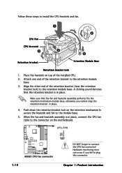
... purchase. • You do not have to remove the retention module base when installing the CPU or installing other motherboard components. • If you purchased a separate CPU heatsink and fan assembly, make sure that a Thermal Interface Material is in place, push down the socket lever ... Athlon™ 64FX or AMD Athlon 64™ processor require a specially designed heatsink and fan assembly to prevent bending the pins and damaging the CPU! 5. ASUS A8N5X 1-11 DO NOT force the CPU into the socket until it is already installed on the side tab to indicate that the CPU corner with...
... purchase. • You do not have to remove the retention module base when installing the CPU or installing other motherboard components. • If you purchased a separate CPU heatsink and fan assembly, make sure that a Thermal Interface Material is in place, push down the socket lever ... Athlon™ 64FX or AMD Athlon 64™ processor require a specially designed heatsink and fan assembly to prevent bending the pins and damaging the CPU! 5. ASUS A8N5X 1-11 DO NOT force the CPU into the socket until it is already installed on the side tab to indicate that the CPU corner with...
A8N5X User's Manual for English Edition
Page 26
Align the other end of the retention bracket to the retention module base. CPU_FAN GND +12V Rotation A8N5X ® A8N5X CPU fan connector 1-12 DO NOT forget to install the CPU heatsink and fan. 1 2 CPU Fan CPU Heatsink 3 4 5 Retention bracket Retention ... one end of the retention bracket (near the retention bracket lock) to the retention module base. 3. Push down the retention bracket lock on the motherboard. Make sure that the retention bracket is in place. 4. Chapter 1: Product introduction A clicking sound denotes that the fan and heatsink assembly perfectly fits...
Align the other end of the retention bracket to the retention module base. CPU_FAN GND +12V Rotation A8N5X ® A8N5X CPU fan connector 1-12 DO NOT forget to install the CPU heatsink and fan. 1 2 CPU Fan CPU Heatsink 3 4 5 Retention bracket Retention ... one end of the retention bracket (near the retention bracket lock) to the retention module base. 3. Push down the retention bracket lock on the motherboard. Make sure that the retention bracket is in place. 4. Chapter 1: Product introduction A clicking sound denotes that the fan and heatsink assembly perfectly fits...

A8N5X User's Manual for English Edition
Page 27
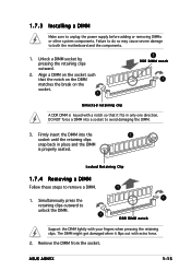
...Always install DIMMs with four 184-pin Double Data Rate (DDR) Dual Inline Memory Modules (DIMM) sockets. ASUS A8N5X 1-13 The following figure illustrates the location of the sockets: DIMM_A1 DIMM_A2 DIMM_B1 DIMM_B2 A8N5X ® A8N5X 184-pin DDR DIMM sockets Channel Channel A Channel B Sockets DIMM_A1 and DIMM_A2 DIMM_B1 and DIMM_B2 1.7.2 Memory ... • Due to CPU limitation, DIMM modules with 128 Mb memory chips or double-sided x16 memory chips are not supported in this motherboard. 1.7 System memory 1.7.1 Overview The motherboard comes with the same CAS latency.
...Always install DIMMs with four 184-pin Double Data Rate (DDR) Dual Inline Memory Modules (DIMM) sockets. ASUS A8N5X 1-13 The following figure illustrates the location of the sockets: DIMM_A1 DIMM_A2 DIMM_B1 DIMM_B2 A8N5X ® A8N5X 184-pin DDR DIMM sockets Channel Channel A Channel B Sockets DIMM_A1 and DIMM_A2 DIMM_B1 and DIMM_B2 1.7.2 Memory ... • Due to CPU limitation, DIMM modules with 128 Mb memory chips or double-sided x16 memory chips are not supported in this motherboard. 1.7 System memory 1.7.1 Overview The motherboard comes with the same CAS latency.
A8N5X User's Manual for English Edition
Page 29
... from the socket. Failure to do so may cause severe damage to remove a DIMM. 2 1. Locked Retaining Clip 1.7.4 Removing a DIMM Follow these steps to both the motherboard and the components. 1. 1.7.3 Installing a DIMM Make sure to avoid damaging the DIMM. 3. ASUS A8N5X 1-15
... from the socket. Failure to do so may cause severe damage to remove a DIMM. 2 1. Locked Retaining Clip 1.7.4 Removing a DIMM Follow these steps to both the motherboard and the components. 1. 1.7.3 Installing a DIMM Make sure to avoid damaging the DIMM. 3. ASUS A8N5X 1-15
A8N5X User's Manual for English Edition
Page 30
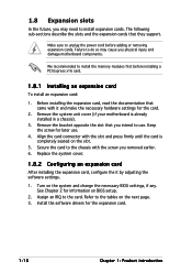
.... 6. The following sub-sections describe the slots and the expansion cards that you intend to install expansion cards. Remove the system unit cover (if your motherboard is completely seated on the next page. 3. Refer to the tables on the slot. 5. Failure to do so may need to use . 4. Replace the system..., if any. See Chapter 2 for the expansion card. 1-16 Chapter 1: Product introduction 1.8 Expansion slots In the future, you may cause you physical injury and damage motherboard components.
.... 6. The following sub-sections describe the slots and the expansion cards that you intend to install expansion cards. Remove the system unit cover (if your motherboard is completely seated on the next page. 3. Refer to the tables on the slot. 5. Failure to do so may need to use . 4. Replace the system..., if any. See Chapter 2 for the expansion card. 1-16 Chapter 1: Product introduction 1.8 Expansion slots In the future, you may cause you physical injury and damage motherboard components.
A8N5X User's Manual for English Edition
Page 31
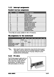
... PCI steering* PS/2 Compatible Mouse Port* Numeric Data Processor Primary IDE Channel Secondary IDE Channel * These IRQs are usually available for this motherboard A B C D E F G H PCI slot 1 shared - - -- - - - Onboard USB 1.0 controller shared - - -- - - - ASUS A8N5X 1-17 IRQ assignments for ISA or PCI devices. PCI slot 3 - - Otherwise, conflicts will arise between the two PCI groups, making the...
... PCI steering* PS/2 Compatible Mouse Port* Numeric Data Processor Primary IDE Channel Secondary IDE Channel * These IRQs are usually available for this motherboard A B C D E F G H PCI slot 1 shared - - -- - - - Onboard USB 1.0 controller shared - - -- - - - ASUS A8N5X 1-17 IRQ assignments for ISA or PCI devices. PCI slot 3 - - Otherwise, conflicts will arise between the two PCI groups, making the...


